
Related Manuals for MSI AmethystM


Summary of Contents for MSI AmethystM
- Page 1 MS-7184 (v1.X) AmethystM Micro ATX Mainboard ATI RS482 + SB400 Based English Version...
-
Page 2: Fcc-B Radio Frequency Interference Statement
Manual Rev: 1.1 Release Date: May 2005 FCC-B Radio Frequency Interference Statement This equipment has been tested and found to comply with the limits for a class B digital device, pursuant to part 15 of the FCC rules. These limits are designed to provide reasonable protection against harmful interference when the equipment is operated in a commercial environment. -
Page 3: Copyright Notice
Copyright Notice T he material in this document is the intellec tual property of M ICRO-STAR INTERNATIONAL. W e take every care in the preparation of this document, but no guarantee is given as to the correctness of its contents. Our products are under continual improvement and we reserve the right to make changes without notice. -
Page 4: Technical Support
Alternatively, please try the following help resources for further guidance. † Visit the MSI homepage & FAQ site for technical guide, BIOS updates, driver updates, and other information: http://www.msi.com.tw & http://www.msi. -
Page 5: Table Of Contents
CONTENTS FCC-B Radio Frequency Interference Statement ............ii Copyright Notice ......................iii Revision History ......................iii Technical Support ......................iv Safety Instructions ......................iv Chapter 1. Getting Started ..................1-1 Mainboard Specifications ................... 1-2 Mainboard Layout ....................1-5 Chapter 2. Hardware Setup .................. 2-1 Quick Components Guide ................... - Page 6 PCI Express Slots ..................2-18 PCI (Peripheral Component Interconnect) Slots ........2-17 PCI Interrupt Request Routing ..............2-19...
-
Page 7: Chapter 1. Getting Started
Getting Started Ch ap ter 1 . Get ti ng Started Getting Started Thank you for choosing the MS-7184 Series (MS-7184 v1.X) Micro ATX mainboard. The MS-7184 Series mainboards are based on ® ® RS482 & ATi SB400 chipsets for optimal system efficiency. ®... -
Page 8: Mainboard Specifications
Mainboard Specifications † Supports 64-bit AMD ® Athlon 64 and Athlon 64 FX processor (Socket 939) † Supports up to 4000+ Athlon 64 FX-55, or higher CPU (For the latest information about CPU, please visit http://www.msi.com.tw/pro- gram/products/mainboard/mbd/pro_mbd_cpu_support.php) Chipset † ATI ®... - Page 9 Getting Started MSI Reminds You... 1. Please note that users cannot install OS, either WinME or Win98, in their SATA hard drives. Under these two OSs, SATA can only be used as an ordinary storage device. 2. To create a bootable RAID volume for a Windows 2000 environment, Microsoft’s Windows 2000 Service Pack 4 (SP4) is required.
- Page 10 The 1394 GUID address is burnt in the BIOS core. If the 1394 GUID address is lost due to an unpredictable event, such as replac- ing a new BIOS chip, users can use the utility from MSI’s website by entering the 1394 GUID address to recover its original one.
-
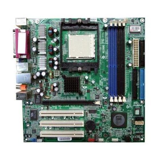
Page 11: Mainboard Layout
Getting Started Mainboard Layout Top : mouse Bottom: keyboard SMSC LPC47M997-NR Top : Parallel Port Bottom: VGA Port(optional) T: 1394 Port B: USB ports JPW1 T: LAN jack B: USB ports RS482 SFAN1 SPDIF-out Line-In Line-Out RTL8100C PCIE16X1 PCI1 BIOS VT6307 PCI2 SB400... -
Page 12: Chapter 2. Hardware Setup
Hardware Setup Chapter 2. Hardware Setup Hardware Setup This chapter tells you how to install the CPU, memory modules, and expansion cards, as well as how to setup the jumpers on the mainboard. Also, it provides the instructions on connecting the pe- ripheral devices, such as the mouse, keyboard, etc. -
Page 13: Quick Components Guide
MS-7184 M-ATX Mainboard Quick Components Guide JPW1, p.2-9 DDR DIMMs, p.2-7 CPU, p.2-3 SFAN1, p.2-11 CFAN1, p.2-11 Back Panel I/O, p.2-10 ATX1, p.2-9 FDD1, p.2-11 PCI Express IDE1/2, p.2-12 Slot, p.2-18 PCI Slots, p.2-18 SATA1~2, p.2-13 JLPC1,p.2-15 JPWD1,p.2-17 JCMOS1, JCD1, p.2-14 J1394_1, p.2-15 JFP1, p.2-16 JAUD1, p.2-14... -
Page 14: Central Processing Unit: Cpu
If you do not have the heat sink and cooling fan, contact your dealer to purchase and install them before turning on the computer. For the latest information about CPU, please visit http://www.msi.com.tw/pro- gram/products/mainboard/mbd/pro_mbd_cpu_support.php. MSI Reminds You... -
Page 15: Cpu Installation Procedures For Socket 939
MS-7184 M-ATX Mainboard CPU Installation Procedures for Socket 939 1. Please turn off the power and unplug the power cord before Open Lever installing the CPU. Sliding 90 degree Plate 2. Pull the lever s ideways away from the socket. Make sure to raise the lever up to a 90-de- gree angle. -
Page 16: Installing Amd Athlon64 Cpu Cooler Set
MSI Reminds You... Mainboard photos shown in this section are for demonstration of the cooler installation for Socket 939 CPUs only. The appearance of your mainboard may vary depending on the model you purchase. - Page 17 Safety Hook Fixed Lever Fixed Bolt MSI Reminds You... While disconnecting the Safety Hook from the fixed bolt, it is neces- sary to keep an eye on your fingers, because once the Safety Hook is disconnected from the fixed bolt, the fixed lever will spring back...
-
Page 18: Memory
128MB~1GB 128MB~1GB 128MB~1GB Dual Channel MSI Reminds You... - The system operates ONLY when the DDR modules are installed in accordance with the above-mentioned memory population rules. - In dual-channel mode, make sure that you install memory modules of the same type and density on DDR DIMMs. -
Page 19: Installing Ddr Modules
MS-7184 M-ATX Mainboard Installing DDR Modules The DDR DIMM has only one notch on the center of module. The module will only fit in the right orientation. Insert the DIMM memory module vertically into the DIMM slot. Then push it in until the golden finger on the memory module is deeply inserted in the socket. -
Page 20: Power Supply
JPW1 Pin Definition JPW1 SIGNAL MSI Reminds You... 1. These two connectors connect to the ATX power supply and have to work together to ensure stable operation of the mainboard. 2. Power supply of 350 watts (and above) is highly recommended for system stability. -
Page 21: Back Panel
MS-7184 M-ATX Mainboard Back Panel L-In Parallel M ou se 1394 Port L-Out Keyboard VGA Port SPDIF-Out USB Ports M ouse/Keyboard Connector USB Ports Pin5 Mouse/KBD Clock Pin6 NC SIGNAL -Data Pin4 VCC Pin3 GND +Data Pin1 Pin2 NC Mouse/KBD DATA RJ-45 LAN Jack IEEE 1394 Port... -
Page 22: Connectors
CPU fan control. SENSOR SENSOR +1 2V +1 2V CFAN1 SFAN1 MSI Reminds You... ® Please refer to the recommended CPU fans at AMD official website or consult the vendors for proper CPU cooling fan. 2-11... -
Page 23: Ata133 Hard Disk Connectors: Ide1 & Ide2
IDE2 (Secondary IDE Connector) IDE2 can also connect a Master and a Slave drive. MSI Reminds You... If you install two hard disks on cable, you must configure the second drive to Slave mode by setting its jumper. Refer to the hard disk docu- mentation supplied by hard disk vendors for jumper setting instructions. -
Page 24: Serial Ata Connectors: Sata1~Sata2
Serial ATA cable Take out the dust cover and connect to the hard disk devices Connect to SATA1/2 MSI Reminds You... Please do not fold the Serial ATA cable into 90-degree angle. Otherwise, data loss may occur during transmission. 2-13... -
Page 25: Cd-In Connector: Jcd1
Left channel audio signal to front panel AUD_RET_L Left channel audio signal return from front panel MSI Reminds You... If you don’t want to connect to the front audio header, pins 5 & 6, 9 & 10 have to be jumpered in order to have signal output directed to the rear audio ports. -
Page 26: Ieee 1394 Connectors: J1394_1
Hardware Setup IEEE 1394 Connectors: J1394_1 The mainboard provides one 1394 pin header that allows you to connect IEEE 1394 ports via an external IEEE1394 bracket (optional). Pin Definition SIGNAL SIGNAL TPA+ TPA- J1394_1 Ground Ground TPB+ TPB- Cable power Cable power Connected to J1394_1 Key (no pin) -
Page 27: Front Panel Connectors: Jfp1
USB1- USB0+ USB1+ JUSB1, JUSB2 (USB 2.0) Key (no pin) USBOC Connected to JUSB1 or JUSB2 USB 2.0 Bracket (Optional) MSI Reminds You... Note that the pins of VCC and GND must be connected correctly to avoid possible damage. 2-16... -
Page 28: Jumpers
JCMOS1 (Clear CMOS Jumper ) to clear data. JCMOS1 Keep Data Clear Data MSI Reminds You... To clear CMOS you should: 1. switch off the system and short 2-3 pin of the JCMOS1; 2. switch on the system again and the message “CMOS checksum error”... -
Page 29: Slots
MS-7184 M-ATX Mainboard Slots The motherboard provides one PCI Express x16 slot and three 32-bit PCI bus slots for expansion card. PCI Express x16 slot PCI Slots PCI Express Slots The PCI Express slot, as a high-bandwidth, low pin count, serial, interconnect technology, supports Intel highest performance desktop platforms utilizing the Intel Pentium 4 processor with HT Technology. - Page 30 Hardware Setup PCI Interrupt Request Routing The IRQ, acronym of interrupt request line and pronounced I-R-Q, are hard- ware lines over which devices can send interrupt signals to the microprocessor. The PCI IRQ pins are typically connected to the PCI bus pins as follows: Order 1 Order 2 Order 3...
Need help?
Do you have a question about the AmethystM and is the answer not in the manual?
Questions and answers