Table of Contents
Advertisement
English
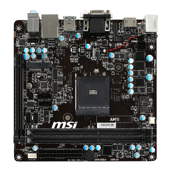
Thank you for choosing the AM1I Series (MS-7865 v2.X) Mini-ITX motherboard. The
AM1I Series motherboards are designed to fit the advanced AMD AM1 processor,
the AM1I Series motherboards deliver a high performance and professional desktop
platform solution.
Layout
T: mouse
B:keyboard
JPWR1
HDMI port
T: VGA
B: DVI-D
JUSB2
JUSB1
USB3.0 ports
T: LAN Jack
B: USB2.0 ports
T:Line-In
M:Line- Out
B:Mic-In
JAUD1
JCI1
JBAT1
JTPM1
SATA1 SATA2
PCI_E1
11
CPUFAN1
JFP1
JCOM1
Advertisement
Table of Contents

Related Manuals for MSI MS-7865


Summary of Contents for MSI MS-7865
- Page 1 English Thank you for choosing the AM1I Series (MS-7865 v2.X) Mini-ITX motherboard. The AM1I Series motherboards are designed to fit the advanced AMD AM1 processor, the AM1I Series motherboards deliver a high performance and professional desktop platform solution. Layout T: mouse...
-
Page 2: Motherboard Specifications
Motherboard Specifications Processor ■ AMD Socket AM1 Processors Memory ■ 2x DDR3 memory slots supporting up to 32GB Support ■ Supports DDR3 1600/ 1333/ 1066 MHz ■ Single channel memory architecture ■ Supports non-ECC, un-buffered memory Expansion ■ 1x PCIe 2.0 x16 slot, supports x4 speed Slots ■... - Page 3 ACPI 5.0, PnP 1.0a, SM BIOS 2.7, DMI 2.0 ■ Multi-language Form Factor ■ Mini-ITX Form Factor ■ 6.7 in. x 6.7 in. (17.0 cm x 17.0 cm) For the latest information about CPU, please visit http://www.msi.com/service/cpu-support/ For more information on compatible components, please visit http://www.msi.com/service/test-report/...
-
Page 4: Back Panel
Back Panel PS/2 Mouse USB 3.0 HDMI DVI-D PS/2 Keyboard USB 2.0 Audio ® LAN LED Indicator LINK/ACT SPEED LED Status Description No link Link/ Activity LED Yellow Linked Blinking Data activity 10 Mbps connection Speed LED Green 100 Mbps connection Orange 1 Gbps connection Audio 2, 4, 6 or 8-channel configuration... -
Page 5: Apu & Heatsink Installation
APU & Heatsink Installation When installing an APU, always remember to install an APU heatsink. An APU heatsink is necessary to prevent overheating and maintain system stability. Follow the steps below to ensure correct APU and heatsink installation. Wrong installation can damage both the APU and the motherboard. - Page 6 Locate the CPUFAN connector on the motherboard. Place the heatsink on the motherboard with the fan’s cable facing towards the fan connector and the fasteners matching the holes on the motherboard. Align the protrusion of the push-pin with the notch of the fastener as shown in the picture.
- Page 7 Memory These DIMM slots are used for installing memory modules. For more information on compatible components, please visit http://www.msi.com/service/test-report/ DIMM1 DIMM2 Video Demonstration Watch the video to learn how to install memories at the address below. http://youtu.be/76yLtJaKlCQ Important • DDR3 memory modules are not interchangeable with DDR2, and the DDR3 standard is not backward compatible.
-
Page 8: Jpwr1~2: Atx Power Connectors
Internal Connectors JPWR1~2: ATX Power Connectors These connectors allow you to connect an ATX power supply. To connect the ATX power supply, align the power supply cable with the connector and firmly press the cable into the connector. If done correctly, the clip on the power cable should be hooked on the motherboard’s power connector. -
Page 9: Jci1: Chassis Intrusion Connector
SATA1~2: SATA Connectors This connector is a high-speed SATA interface port. Each connector can connect to one SATA device. SATA devices include disk drives (HDD), solid state drives (SSD), and optical drives (CD/ DVD/ Blu-Ray). Video Demonstration Watch the video to learn how to Install SATA HDD. http://youtu.be/RZsMpqxythc SATA1 SATA2... -
Page 10: Cpufan1,Sysfan1: Fan Power Connectors
CPUFAN1,SYSFAN1: Fan Power Connectors The fan power connectors support system cooling fans with +12V. If the motherboard has a System Hardware Monitor chipset on-board, you must use a specially designed fan with a speed sensor to take advantage of the fan control. Remember to connect all system fans. -
Page 11: System Panel Connectors
JFP1: System Panel Connectors These connectors connect to the front panel switches and LEDs. The JFP1 connector is compliant with the Intel Front Panel I/O Connectivity Design Guide. ® When installing the front panel connectors, please use the optional M-Connector to simplify installation. -
Page 12: Jtpm1: Tpm Module Connector
JTPM1: TPM Module Connector This connector connects to a TPM (Trusted Platform Module). Please refer to the TPM security platform manual for more details and usages. JBAT1: Clear CMOS Jumper There is CMOS RAM onboard that is external powered from a battery located on the motherboard to save system configuration data. - Page 13 PCI_E1: PCIe x16 Expansion Slot The PCIe slot supports the PCIe interface expansion card. MINI_PCI_E1: Mini-PCIe Expansion Slot The Mini-PCIe slot supports the Mini-PCIe interface expansion card. Important When adding or removing expansion cards, always turn off the power supply and unplug the power supply power cable from the power outlet.
-
Page 14: Entering Bios Setup
BIOS Setup The default settings offer the optimal performance for system stability in normal conditions. You may need to run the Setup program when: ■ An error message appears on the screen during the system booting up, and requests you to run SETUP. ■... -
Page 15: Oc Menu
OC Menu Important Overclocking your PC manually is only recommended for advanced users. • • Overclocking is not guaranteed, and if done improperly, can void your warranty or severely damage your hardware. • If you are unfamiliar with overclocking, we advise you to use OC Genie for easy overclocking. - Page 16 [UnLink] Allows user to configure the DRAM timing manually for respective memory channel. ▶ Advanced DRAM Configuration Press <Enter> to enter the sub-menu. This sub-menu will be activated after setting [Link] or [Unlink] in “DRAM Timing Mode”. User can set the memory timing for each memory channel.
- Page 17 ▶ Overclocking Profile 1/ 2/ 3/ 4/ 5/ 6 Overclocking Profile 1/ 2/ 3/ 4/ 5/ 6 management. Press <Enter> to enter the sub-menu. ▶ OC Profile Save to USB Saves OC profile to the USB flash disk drive. The USB flash disk should be FAT32 format only.
- Page 18 ▶ Core C6 State [Enabled] Enables or disables C6 state support. [Enabled] When the CPU enters C6 state, all cores will save architectural state and reduce core voltages to zero volts. Wake up the CPU from C6 state will take a lot longer. [Disabled] Disables this function.
Need help?
Do you have a question about the MS-7865 and is the answer not in the manual?
Questions and answers