Table of Contents
Advertisement
Quick Links
Advertisement
Table of Contents

Related Manuals for Lenovo ThinkSystem SR530


Summary of Contents for Lenovo ThinkSystem SR530
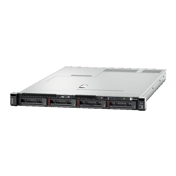
- Page 1 ThinkSystem SR530 Maintenance Manual Machine Types: 7X07 and 7X08...
- Page 2 Before using this information and the product it supports, be sure to read and understand the safety information and the safety instructions, which are available at: http://thinksystem.lenovofiles.com/help/topic/safety_documentation/pdf_files.html In addition, be sure that you are familiar with the terms and conditions of the Lenovo warranty for your server, which can be found at: http://datacentersupport.lenovo.com/warrantylookup Eleventh Edition (June 2021) ©...
-
Page 3: Table Of Contents
Top cover replacement ... . Hot-swap power supply replacement ..Remove the top cover ..© Copyright Lenovo 2017, 2021... - Page 4 Index ....171 Event logs ....145 General problem determination procedures ..147 ThinkSystem SR530 Maintenance Manual...
-
Page 5: Safety
Vor der Installation dieses Produkts die Sicherheitshinweise lesen. Prima di installare questo prodotto, leggere le Informazioni sulla Sicurezza. Les sikkerhetsinformasjonen (Safety Information) før du installerer dette produktet. Antes de instalar este produto, leia as Informações sobre Segurança. © Copyright Lenovo 2017, 2021... -
Page 6: Safety Inspection Checklist
1 & IEC 60950-1, the standard for Safety of Electronic Equipment within the Field of Audio/Video, Information Technology and Communication Technology. Lenovo assumes you are qualified in the servicing of equipment and trained in recognizing hazards energy levels in products. Access to the equipment is by the use of a tool, lock and key, or other means of security, and is controlled by the authority responsible for the location. - Page 7 Click the Power tab to see all line cords. • Make sure that the insulation is not frayed or worn. 3. Check for any obvious non-Lenovo alterations. Use good judgment as to the safety of any non-Lenovo alterations. 4. Check inside the server for any obvious unsafe conditions, such as metal filings, contamination, water or other liquid, or signs of fire or smoke damage.
- Page 8 ThinkSystem SR530 Maintenance Manual...
-
Page 9: Chapter 1. Introduction
Identifying your server When you contact Lenovo for help, the machine type and serial number information helps support technicians to identify your server and provide faster service. The machine type and serial number are on the ID label on the right rack latch in the front of the server. -
Page 10: Specifications
Scan the QR code with a mobile device and a QR code reader application to get quick access to the Lenovo Service web site for this server. The Lenovo Service Information Web site provides additional information for parts installation and replacement videos, and error codes for server support. - Page 11 – Designed for Land Grid Array (LGA) 3647 socket – Scalable up to 20 cores For a list of supported processors, see: https://static.lenovo.com/us/en/serverproven/index.shtml Memory For 1st Generation Intel Xeon Scalable Processor (SP Gen 1) : • Minimum: 8 GB •...
- Page 12 – One VGA connector – Two USB 3.0 connectors – Two Ethernet connectors (RJ-45) – One XClarity Controller network connector – Two Ethernet connectors on the LOM adapter* – One serial port* * Available on some models ThinkSystem SR530 Maintenance Manual...
- Page 13 Table 1. Server specifications (continued) Specification Description RAID adapters (depending on • A RAID 530-8i SAS/SATA adapter that supports JBOD mode and RAID levels 0, 1, the model) 5, 10, and 50 • A RAID 730-8i 1G Cache SAS/SATA adapter that supports JBOD mode and RAID levels 0, 1, 5, 10, and 50 •...
- Page 14 • In order for the ThinkSystem products to operate error free in both a DC or AC electrical environment, a TN-S earthing system which complies to 60364- 1 IEC 2005 standard has to be present or installed. ThinkSystem SR530 Maintenance Manual...
- Page 15 Table 1. Server specifications (continued) Specification Description Minimal configuration for • One processor in processor socket 1 debugging • One DIMM in slot 3 • One power supply • One HDD or M.2 (If OS installation is needed for debugging) •...
-
Page 16: Particulate Contamination
If Lenovo determines that the levels of particulates or gases in your environment have caused damage to the device, Lenovo may condition provision of repair or replacement of devices or parts on implementation of appropriate remedial measures to mitigate such environmental contamination. -
Page 17: Firmware Updates
Note: Lenovo typically releases firmware in bundles called UpdateXpress System Packs (UXSPs). To ensure that all of the firmware updates are compatible, you should update all firmware at the same time. If you are updating firmware for both the Lenovo XClarity Controller and UEFI, update the firmware for Lenovo XClarity Controller first. - Page 18 Machine-type-specific firmware-only UXSPs are also available. See the following table to determine the best Lenovo tool to use for installing and setting up the firmware: Note: The server UEFI settings for option ROM must be set to Auto or UEFI to update firmware using Lenovo XClarity Administrator or Lenovo XClarity Essentials.
- Page 19 • Lenovo XClarity Provisioning Manager From Lenovo XClarity Provisioning Manager, you can update the Lenovo XClarity Controller firmware, the UEFI firmware, and the Lenovo XClarity Provisioning Manager software. Note: By default, the Lenovo XClarity Provisioning Manager Graphical User Interface is displayed when you press F1.
- Page 20 • Lenovo XClarity Controller If you need to install a specific update, you can use the Lenovo XClarity Controller interface for a specific server. Notes: – To perform an in-band update through Windows or Linux, the operating system driver must be installed and the Ethernet-over-USB (sometimes called LAN over USB) interface must be enabled.
-
Page 21: Configuring The Lan Over Usb Interface
Step 8. Return to the Device Manager. Lenovo USB Remote NDIS Network Device appears under Network Adapters. Step 9. Use the Lenovo XClarity Controller interface to view or set the IP address for the LAN adapter. Chapter 1 Introduction... -
Page 22: Tech Tips
Power off the server The server remains in a standby state when it is connected to a power source, allowing the Lenovo XClarity Controller to respond to remote power-on requests. To remove all power from the server (power status LED off), you must disconnect all power cables. - Page 23 • Press and hold the power button for more than 4 seconds to force a shutdown. When in a standby state, the server can respond to remote power-on requests sent to the Lenovo XClarity Controller. For information about powering on the server, see “Power on the server” on page 14.
- Page 24 ThinkSystem SR530 Maintenance Manual...
-
Page 25: Chapter 2. Server Components
Pull-out information tab XClarity Controller USB connector USB 3.0 connector Operator information panel Rack latch (right) Drive bays Drive status LED (yellow) Drive activity LED (green) Rack latch (left) VGA connector (available on some models) © Copyright Lenovo 2017, 2021... - Page 26 Used to attach a high-performance monitor, a direct-drive monitor, or other devices that use a VGA connector. Pull-out information tab The Lenovo XClarity Controller network access label is attached on the pull-out information tab. XClarity Controller USB connector Depending on the setting, this connector supports USB 2.0 function, XClarity Controller management function, or both.
-
Page 27: Operator Information Panel
Each hot-swap drive has two LEDs. Drive LED Description Status Solid yellow The drive has an error. The drive is being rebuilt. Blinking yellow (blinking slowly, about Drive status LED (right) one flash per second) Blinking yellow (blinking rapidly, The RAID controller is locating the about four flashes per second) drive. - Page 28 Each time you press the system ID button, the state of both the system ID LEDs changes. The LEDs can be changed to on, blinking, or off. You can also use the Lenovo XClarity Controller or a remote management program to change the state of the system ID LEDs to assist in visually locating the server among other servers.
-
Page 29: Rear View
Rear view The rear of the server provides access to several components, including the power supplies, PCIe adapters, serial port, and Ethernet connectors. • “Rear view of server models with three PCIe slots” on page 21 • “Rear view of server models with two PCIe slots” on page 23 Rear view of server models with three PCIe slots The following illustration shows the rear view of server models with three PCIe slots. - Page 30 The hot-swap redundant power supplies help you avoid significant interruption to the operation of the system when a power supply fails. You can purchase a power supply option from Lenovo and install the power supply to provide power redundancy without turning off the server.
- Page 31 The hot-swap redundant power supplies help you avoid significant interruption to the operation of the system when a power supply fails. You can purchase a power supply option from Lenovo and install the power supply to provide power redundancy without turning off the server.
- Page 32 Ethernet connector 1 on the LOM adapter can be set as XClarity Controller Network connector. To set the Ethernet connector as XClarity Controller Network connector, start Setup utility, go to BMC Settings ➙ Network Settings ➙ Network Interface Port and select Shared. Then, go to Shared NIC on and select PHY Card. ThinkSystem SR530 Maintenance Manual...
-
Page 33: Rear View Leds
Each time you press the system ID button, the state of both the system ID LEDs changes. The LEDs can be changed to on, blinking, or off. You can also use the Lenovo XClarity Controller or a remote management program to change the state of the system ID LEDs to assist in visually locating the server among other servers. - Page 34 LED is off, replace the power supply. • Yellow: The power supply has failed. To resolve the issue, replace the power supply. Power supply error LED • Off: The power supply is working normally ThinkSystem SR530 Maintenance Manual...
-
Page 35: System Board Components
System board components The illustration in this section shows the component locations on the system board. Figure 10. System board components Callout Callout Riser 1 slot Serial-port-module connector LOM adapter connector /TPM connector (for Chinese Mainland only) Front USB connector Front VGA connector DIMM slots Processor 1 socket... - Page 36 Callout Callout Internal USB connector Power supply 1 connector SATA 0-3 connector M.2 module slot Riser 2 slot Notes: • Trusted Cryptography Module • Trusted Platform Module ThinkSystem SR530 Maintenance Manual...
-
Page 37: System Board Switches And Jumpers
System board switches and jumpers The following illustration shows the location of the switches and jumpers on the server. Note: If there is a clear protective sticker on the top of the switch blocks, you must remove and discard it to access the switches. - Page 38 The default position is Off. Changing this switch to the On Force XCC update SW6 (switch 3) position forces the Lenovo XClarity Controller to update to the latest version. Important: • Before you move the switches and jumpers, turn off the server. Then, disconnect all power cords and external cables.
-
Page 39: System Board Leds
System board LEDs The following illustrations show the light-emitting diodes (LEDs) on the system board. Figure 12. System board LEDs Table 9. LEDs on the system board Callout Callout System error LED System ID LED XClarity Controller heartbeat LED Field-Programmable Gate Array (FPGA) error LED System power LED Chapter 2 Server components... -
Page 40: Internal Cable Routing
Note: Disengage all latches, release tabs, or locks on cable connectors when you disconnect cables from the system board. Failing to release them before removing the cables will damage the cable sockets on the system board, which are fragile. Any damage to the cable sockets might require replacing the system board. ThinkSystem SR530 Maintenance Manual... -
Page 41: Vga Connector
VGA connector Use this section to understand the cable routing for the video graphic adapter (VGA) connector. Note: The VGA connector is available on some models. Server models with 3.5-inch drive bays Figure 13. VGA connector cable routing From VGA cable Front VGA connector on the system board Chapter 2 Server components... - Page 42 Server models with 2.5-inch drive bays Figure 14. VGA connector cable routing From VGA cable Front VGA connector on the system board ThinkSystem SR530 Maintenance Manual...
-
Page 43: Front I/O Assembly
Front I/O assembly Use this section to understand the cable routing for the front I/O assembly. Figure 15. Cable routing for the front I/O assembly From Front USB cable Front USB connector on the system board Operator-information-panel cable Operator-information-panel connector on the system board Chapter 2 Server components... -
Page 44: Raid Super Capacitor Module
Cable routing for RAID super capacitor module 1 Cable routing for RAID super capacitor module 2 An extension cable is provided for each RAID super capacitor module for connection. Figure 16. Connecting the RAID super capacitor module to the RAID adapter ThinkSystem SR530 Maintenance Manual... -
Page 45: Backplanes
Backplanes Use this section to understand the cable routing for the backplanes. Server model with eight 2.5-inch hot-swap drives Use this section to understand the internal cable routing for the server model with eight 2.5-inch hot-swap drives. The following illustration shows the cable routing for the server model with eight 2.5-inch hot-swap drives. Figure 17. - Page 46 Figure 18. Cable routing for the server model with four 3.5-inch hot-swap drives From Cable Power cable Power connector on the backplane Backplane power connector on the system board SAS signal SAS 0 connector on the backplane C0 connector on the HBA/RAID adapter cable ThinkSystem SR530 Maintenance Manual...
- Page 47 Server model with four 3.5-inch simple-swap drives Use this section to understand the internal cable routing for the server model with four 3.5-inch simple-swap drives. Figure 19. Cable routing for the server model with four 3.5-inch simple-swap drives The simple-swap drive backplate assembly comes with a power cable and a SATA signal cable. From Power cable of the backplate assembly Backplane power connector on the system board...
-
Page 48: Parts List
Note: Depending on the model, your server might look slightly different from the following illustration. Some of the components might not be available on your server. Figure 20. Server components The parts listed in the following table are identified as one of the following: ThinkSystem SR530 Maintenance Manual... - Page 49 Tier 1 CRU at your request with no service agreement, you will be charged for the installation. • Tier 2 customer replaceable unit (CRU): You may install a Tier 2 CRU yourself or request Lenovo to install it, at no additional charge, under the type of warranty service that is designated for your server.
- Page 50 CMOS battery (CR2032) √ Backplane for eight hot-swap 2.5-inch drives √ Simple-swap drive backplate assembly √ Backplane for four hot-swap 3.5-inch drives √ TCM/TPM adapter (for Chinese Mainland only) √ DIMM √ Processor √ Processor heat sink √ ThinkSystem SR530 Maintenance Manual...
-
Page 51: Power Cords
Several power cords are available, depending on the country and region where the server is installed. To view the power cords that are available for the server: 1. Go to: http://dcsc.lenovo.com/#/ 2. Click Preconfigured Model or Configure to order. 3. Enter the machine type and model for your server to display the configurator page. - Page 52 ThinkSystem SR530 Maintenance Manual...
-
Page 53: Chapter 3. Hardware Replacement Procedures
Go to to download firmware updates for your server. ThinkSystem SR530 Drivers and Software Important: Some cluster solutions require specific code levels or coordinated code updates. If the component is part of a cluster solution, verify that the latest level of code is supported for the cluster solution before you update the code. -
Page 54: Safety Inspection Checklist
1 & IEC 60950-1, the standard for Safety of Electronic Equipment within the Field of Audio/Video, Information Technology and Communication Technology. Lenovo assumes you are qualified in the servicing of equipment and trained in recognizing hazards energy levels in products. Access to the equipment is by the use of a tool, lock and key, or other means of security, and is controlled by the authority responsible for the location. -
Page 55: System Reliability Guidelines
Click the Power tab to see all line cords. • Make sure that the insulation is not frayed or worn. 3. Check for any obvious non-Lenovo alterations. Use good judgment as to the safety of any non-Lenovo alterations. 4. Check inside the server for any obvious unsafe conditions, such as metal filings, contamination, water or other liquid, or signs of fire or smoke damage. -
Page 56: Handling Static-Sensitive Devices
• When handling a device, carefully hold it by the edges or the frame. • Do not touch solder joints, pins, or exposed circuitry. • Keep the device from others’ reach to prevent possible damages. ThinkSystem SR530 Maintenance Manual... -
Page 57: Rack Latches Replacement
Rack latches replacement Use this information to remove and install the rack latches. Remove the rack latches Use this information to remove the rack latches. “Read the installation Guidelines” on page 45 Before removing the rack latches: 1. If you have installed the security bezel, remove it. See “Remove the security bezel” on page 53. 2. - Page 58 On each side of the server, remove the rack latch from the chassis as shown. Figure 23. Rack latch removal If you are instructed to return the old rack latches, follow all packaging instructions and use any packaging materials that are provided. ThinkSystem SR530 Maintenance Manual...
-
Page 59: Install The Rack Latches
Install the rack latches Use this information to install the rack latches. “Read the installation Guidelines” on page 45 To install the rack latches, complete the following steps: Watch the procedure. A video of the installation process is available: • YouTube: https://www.youtube.com/playlist?list=PLYV5R7hVcs-AQrHuDWK6L3KtHWc6maY_O •... - Page 60 After installing the rack latches: 1. Install the ID label plate to the right rack latch as shown. Figure 26. ID label plate installation 2. Complete the parts replacement. See “Complete the parts replacement” on page 144. ThinkSystem SR530 Maintenance Manual...
-
Page 61: Security Bezel Replacement
Security bezel replacement Use this information to remove and install the security bezel. Remove the security bezel Use this information to remove the security bezel. “Read the installation Guidelines” on page 45 To remove the security bezel, complete the following steps: Step 1. - Page 62 Press the blue release latch and pivot the security bezel outward to remove it from the chassis. Figure 28. Security bezel removal Attention: Before you ship the rack with the server installed, reinstall and lock the security bezel into place. ThinkSystem SR530 Maintenance Manual...
-
Page 63: Install The Security Bezel
Install the security bezel Use this information to install the security bezel. “Read the installation Guidelines” on page 45 Attention: Before you ship the rack with the server installed, install and lock the security bezel into place. Before installing the security bezel, if you have removed the rack latches, reinstall them. See “Install the rack latches”... - Page 64 Insert the tab on the security bezel into the slot on the right side of the chassis. Then, press the blue release latch and pivot the security bezel inward until it clicks into place. Figure 30. Security bezel installation Step 3. Use the key to lock the security bezel. Figure 31. Security bezel lockup ThinkSystem SR530 Maintenance Manual...
-
Page 65: Top Cover Replacement
Top cover replacement Use this information to remove and install the top cover. Remove the top cover Use this information to remove the top cover. “Read the “Power off “ATTENTION: installation the server Static Sensitive Device Guidelines” on for this task” Ground package before opening”... - Page 66 • Handle the top cover carefully. Dropping the top cover with the cover latch open might damage the cover latch. • For proper cooling and airflow, install the top cover before you power on the server. ThinkSystem SR530 Maintenance Manual...
-
Page 67: Install The Top Cover
Install the top cover Use this information to install the top cover. “Read the “Power off “ATTENTION: installation the server Static Sensitive Device Guidelines” on for this task” Ground package before opening” page 45 on page 14 on page 48 Before installing the top cover: 1. -
Page 68: Air Baffle Replacement
Guidelines” on for this task” page 45 on page 14 To remove the air baffle, complete the following steps: Watch the procedure. A video of the removal process is available: • YouTube: https://www.youtube.com/playlist?list=PLYV5R7hVcs-AQrHuDWK6L3KtHWc6maY_O • Youku: http://list.youku.com/albumlist/show/id_50437162 ThinkSystem SR530 Maintenance Manual... - Page 69 Figure 34. Air baffle removal Step 1. Remove the top cover. See “Remove the top cover” on page 57. Step 2. If the server has a RAID super capacitor module installed underneath the air baffle, disconnect its cable from the extension cable. Step 3.
-
Page 70: Install The Air Baffle
1. If you have installed a RAID super capacitor module, connect it to the RAID adapter using the extension cable that comes with the RAID super capacitor module. See “Internal cable routing” on page 32. 2. Complete the parts replacement. See “Complete the parts replacement” on page 144. ThinkSystem SR530 Maintenance Manual... -
Page 71: Raid Super Capacitor Module Replacement
RAID super capacitor module replacement Use this information to remove and install a RAID super capacitor module. Your server supports up to two RAID super capacitor modules. The RAID super capacitor holders are located underneath the air baffle. Remove a RAID super capacitor module Use this information to remove a RAID super capacitor module. - Page 72 ThinkSystem SR530 Maintenance Manual...
-
Page 73: Install A Raid Super Capacitor Module
Install a RAID super capacitor module If your server has a RAID adapter with a super capacitor connector, you can install a RAID super capacitor module in your server. “Read the “Power off “ATTENTION: installation the server Static Sensitive Device Guidelines”... - Page 74 ThinkSystem SR530 Maintenance Manual...
-
Page 75: System Fan Replacement
System fan replacement Use this information to remove and install a system fan. S033 CAUTION: Hazardous energy present. Voltages with hazardous energy might cause heating when shorted with metal, which might result in spattered metal, burns, or both. S009 CAUTION: To avoid personal injury, disconnect the fan cables before removing the fan from the device. - Page 76 After removing the system fan: 1. Install a new fan to cover the fan bay. 2. If you are instructed to return the old system fan, follow all packaging instructions and use any packaging materials that are provided. ThinkSystem SR530 Maintenance Manual...
-
Page 77: Install A System Fan
Install a system fan Use this information to install a system fan. “Read the “Power off “ATTENTION: installation the server Static Sensitive Device Guidelines” on for this task” Ground package before opening” page 45 on page 14 on page 48 Before installing a system fan, touch the static-protective package that contains the new system fan to any unpainted surface on the outside of the server. -
Page 78: Front I/O Assembly Replacement
Remove the screws that secure the front I/O assembly. Step 2. Slide the front I/O assembly out of the assembly bay. If you are instructed to return the old front I/O assembly, follow all packaging instructions and use any packaging materials that are provided. ThinkSystem SR530 Maintenance Manual... -
Page 79: Install The Front I/O Assembly
Install the front I/O assembly Use this information to install the front I/O assembly. “Read the “Power off “ATTENTION: installation the server Static Sensitive Device Guidelines” on for this task” Ground package before opening” page 45 on page 14 on page 48 Before installing the front I/O assembly, touch the static-protective package that contains the new front I/O assembly to any unpainted surface on the outside of the server. -
Page 80: Hot-Swap Drive Backplane Replacement
To remove the backplane, complete the following steps: Watch the procedure. A video of the removal process is available: • YouTube: https://www.youtube.com/playlist?list=PLYV5R7hVcs-AQrHuDWK6L3KtHWc6maY_O • Youku: http://list.youku.com/albumlist/show/id_50437162 Figure 44. Backplane removal Step 1. Open the release latches that secure the backplane. ThinkSystem SR530 Maintenance Manual... -
Page 81: Install The Backplane For Four 3.5-Inch Hot-Swap Drives
Step 2. Pivot the backplane backward slightly to release it from the three pins on the chassis. Step 3. Carefully remove the backplane out of the chassis from under the front I/O assembly cables. If you are instructed to return the old backplane, follow all packaging instructions and use any packaging materials that are provided. -
Page 82: Remove The Backplane For Eight 2.5-Inch Hot-Swap Drives
3. Remove all the installed drives and drive fillers (if any) from the drive bays. See “Remove a hot-swap drive” on page 78. To remove the backplane, complete the following step: Figure 46. Backplane removal Step 1. Grasp the backplane and carefully lift it out of the chassis. ThinkSystem SR530 Maintenance Manual... -
Page 83: Install The Backplane For Eight 2.5-Inch Hot-Swap Drives
If you are instructed to return the old backplane, follow all packaging instructions and use any packaging materials that are provided. Install the backplane for eight 2.5-inch hot-swap drives Use this information to install the backplane for eight 2.5-inch hot-swap drives. “Read the “Power off “ATTENTION:... -
Page 84: Simple-Swap Drive Backplate Assembly Replacement
Pivot the simple-swap drive backplate assembly backward slightly to release it from the three pins on the chassis. Step 3. Carefully remove the backplate assembly out of the chassis from under the front I/O assembly cables. ThinkSystem SR530 Maintenance Manual... -
Page 85: Install The Simple-Swap Drive Backplate
If you are instructed to return the old simple-swap drive backplate assembly, follow all packaging instructions and use any packaging materials that are provided. Install the simple-swap drive backplate assembly Use this information to install the simple-swap drive backplate assembly. “Read the “Power off “ATTENTION:... -
Page 86: Hot-Swap Drive Replacement
To remove a hot-swap drive, complete the following steps: Watch the procedure. A video of the removal process is available: • YouTube: https://www.youtube.com/playlist?list=PLYV5R7hVcs-AQrHuDWK6L3KtHWc6maY_O • Youku: http://list.youku.com/albumlist/show/id_50437162 ThinkSystem SR530 Maintenance Manual... -
Page 87: Install A Hot-Swap Drive
Notes: • For a list of supported drives, see https://static.lenovo.com/us/en/serverproven/index.shtml • The drive bays are numbered to indicate the installation order (starting from number “0”). Follow the installation order when you install a drive. See “Front view” on page 17. - Page 88 Continue to install additional hot-swap drives if necessary. After installing all drives: 1. Reinstall the security bezel. See “Install the security bezel” on page 55. 2. Use the Lenovo XClarity Provisioning Manager to configure the RAID if necessary. For more information, see: ThinkSystem SR530 Maintenance Manual...
-
Page 89: Simple-Swap Drive Replacement
http://sysmgt.lenovofiles.com/help/topic/LXPM/RAID_setup.html Simple-swap drive replacement Use this information to remove and install a simple-swap drive. Notes: • The term “simple-swap drive” refers to all the supported types of simple-swap hard disk drives (HDDs) and simple-swap solid-state drives (SSDs). • You must power off the server before installing or replacing a simple-swap drive. •... - Page 90 Step 3. Install a drive filler or a new drive to cover the drive bay. If you are instructed to return the old drive, follow all packaging instructions and use any packaging materials that are provided. ThinkSystem SR530 Maintenance Manual...
-
Page 91: Install A Simple-Swap Drive
Notes: • For a list of supported drives, see https://static.lenovo.com/us/en/serverproven/index.shtml • The drive bays are numbered to indicate the installation order (starting from number “0”). Follow the installation order when you install a drive. See “Front view” on page 17. -
Page 92: Memory Module Replacement
After you have installed all drives: 1. Reinstall the security bezel. See “Install the security bezel” on page 55. 2. Power on the server. 3. Use the Lenovo XClarity Provisioning Manager to configure the RAID if necessary. For more information, see: http://sysmgt.lenovofiles.com/help/topic/LXPM/RAID_setup.html Memory module replacement Use this information to remove and install a memory module. -
Page 93: Memory Module Installation Rules
Figure 56. Memory module removal Step 1. Open the retaining clips on each end of the memory module slot. Attention: To avoid breaking the retaining clips or damaging the memory module slots, handle the clips gently. Step 2. Grasp the memory module at both ends and carefully lift it out of the slot. Step 3. - Page 94 (CPU1) is installed. Note: If there are three identical memory modules to be installed for CPU1, and the three memory modules have the same Lenovo part number, install the three memory modules in slots 1, 2, and 3. ThinkSystem SR530 Maintenance Manual...
- Page 95 • If there are three identical memory modules to be installed for CPU1, and the three memory modules have the same Lenovo part number, install the three memory modules in slots 1, 2, and 3. • If there are three identical memory modules to be installed for CPU2, and the three memory modules have the same Lenovo part numbers, install the three memory modules in slots 7, 8, and 9.
- Page 96 • All memory modules to be installed must be the same type with the same capacity, frequency, voltage, and number of ranks. • Single-rank memory modules do not support rank sparing mode. Table 17. Rank sparing mode with one processor Processor 1 Total memory Total memory modules modules ThinkSystem SR530 Maintenance Manual...
- Page 97 Table 17. Rank sparing mode with one processor (continued) Processor 1 Total memory Total memory modules modules The following table shows the memory module population sequence for rank sparing mode when two processors (CPU1 and CPU2) are installed. Table 18. Rank sparing mode with two processors Total Processor 2 Processor 1...
-
Page 98: Install A Memory Module
85. Ensure that you observe the installation rules and sequence. To install a memory module, complete the following steps: Watch the procedure. A video of the installation process is available: • YouTube: https://www.youtube.com/playlist?list=PLYV5R7hVcs-AQrHuDWK6L3KtHWc6maY_O • Youku: http://list.youku.com/albumlist/show/id_50437162 ThinkSystem SR530 Maintenance Manual... - Page 99 Figure 58. Memory module installation Step 1. Open the retaining clips on each end of the memory module slot. Attention: To avoid breaking the retaining clips or damaging the memory module slots, open and close the clips gently. Step 2. Align the memory module with the slot, and gently place the memory module on the slot with both hands.
-
Page 100: Cmos Battery Replacement
The following tips describe information that you must consider when removing the CMOS battery. • Lenovo has designed this product with your safety in mind. The lithium CMOS battery must be handled correctly to avoid possible danger. If you replace the CMOS battery, you must adhere to the following instructions. - Page 101 CAUTION: The power-control button on the device and the power switch on the power supply do not turn off the electrical current supplied to the device. The device also might have more than one power cord. To remove all electrical current from the device, ensure that all power cords are disconnected from the power source.
-
Page 102: Install The Cmos Battery
The following tips describe information that you must consider when installing the CMOS battery. • Lenovo has designed this product with your safety in mind. The lithium battery must be handled correctly to avoid possible danger. If you install the CMOS battery, you must adhere to the following instructions. -
Page 103: Tcm/Tpm Adapter Replacement
The power-control button on the device and the power switch on the power supply do not turn off the electrical current supplied to the device. The device also might have more than one power cord. To remove all electrical current from the device, ensure that all power cords are disconnected from the power source. -
Page 104: Install The Tcm/Tpm Adapter
Before installing the TCM/TPM adapter, touch the static-protective package that contains the new TCM/TPM adapter to any unpainted surface on the outside of the server. Then, take the new TCM/TPM adapter out of the package and place it on a static-protective surface. ThinkSystem SR530 Maintenance Manual... - Page 105 To install the TCM/TPM adapter, complete the following steps: Step 1. Locate the TCM/TPM connector on the system board. Step 2. Insert the TCM/TPM adapter into the TCM/TPM connector on the system board. Notes: • Carefully handle the TCM/TPM adapter by its edges. •...
-
Page 106: Hot-Swap Power Supply Replacement
The device also might have more than one power cord. To remove all electrical current from the device, ensure that all power cords are disconnected from the power source. S001 ThinkSystem SR530 Maintenance Manual... - Page 107 DANGER Electrical current from power, telephone, and communication cables is hazardous. To avoid a shock hazard: • Connect all power cords to a properly wired and grounded electrical outlet/source. • Connect any equipment that will be attached to this product to properly wired outlets/sources. •...
- Page 108 To remove a hot-swap power supply, complete the following steps: Watch the procedure. A video of the removal process is available: • YouTube: https://www.youtube.com/playlist?list=PLYV5R7hVcs-AQrHuDWK6L3KtHWc6maY_O • Youku: http://list.youku.com/albumlist/show/id_50437162 ThinkSystem SR530 Maintenance Manual...
- Page 109 Step 1. If the server is in a rack, adjust the cable management arm (CMA) to gain access to the power supply. If you have installed the 1U CMA Upgrade Kit for Toolless Slide Rail or Toolless Slide Rail Kit with 1U CMA, do the following: Figure 64.
- Page 110 This means that each bay must have a power supply installed; or one has a power supply installed and the other has a power supply filler installed. • If you are instructed to return the old power supply, follow all packaging instructions and use any packaging materials that are provided. ThinkSystem SR530 Maintenance Manual...
-
Page 111: Install A Hot-Swap Power Supply
• Ensure that the devices that you are installing are supported. For a list of supported optional devices for the server, go to: https://static.lenovo.com/us/en/serverproven/index.shtml Notes: • Ensure that the two power supplies installed on the server have the same wattage. - Page 112 EQUIPMENT IS POWERED ON WITH DC SUPPLY (hot-plugging). Otherwise you may damage the equipment and result in data loss, the damages and losses result from incorrect operation of the equipment will not be covered by the manufacturers’ warranty. S035 ThinkSystem SR530 Maintenance Manual...
- Page 113 CAUTION: Never remove the cover on a power supply or any part that has this label attached. Hazardous voltage, current, and energy levels are present inside any component that has this label attached. There are no serviceable parts inside these components. If you suspect a problem with one of these parts, contact a service technician.
- Page 114 Rotate the CMA out of the way to gain access to the power supply bay. Step 3. If there is a power supply filler installed, remove it. Figure 68. Hot-swap power supply filler removal ThinkSystem SR530 Maintenance Manual...
- Page 115 Step 4. Slide the new hot-swap power supply into the bay until the release latch clicks into place. Figure 69. Hot-swap power supply installation After installing the power supply: 1. Connect the power cord to the new power supply and ensure that it is connected to a properly grounded electrical outlet.
-
Page 116: Pcie Adapter Replacement
Grasp the PCIe adapter by its edges and carefully pull it out of the PCIe slot on the riser card. If you are instructed to return the old PCIe adapter, follow all packaging instructions and use any packaging materials that are provided. ThinkSystem SR530 Maintenance Manual... -
Page 117: Install A Pcie Adapter
Install a PCIe adapter Use this information to install a PCIe adapter. “Read the “Power off “ATTENTION: installation the server Static Sensitive Device Guidelines” on for this task” Ground package before opening” page 45 on page 14 on page 48 Before installing a PCIe adapter, 1. -
Page 118: Riser Card Replacement
Note: The riser assembly you want to remove might be different from the illustrations below, but the removal method is the same. Step 1. Remove the top cover. See “Remove the top cover” on page 57. ThinkSystem SR530 Maintenance Manual... - Page 119 Step 2. Grasp the riser assembly by its edges and carefully lift it up. Figure 76. Riser assembly removal Step 3. If there is any PCIe adapter installed on the riser card, record the cable connections first. Then, disconnect all cables from the PCIe adapter and completely remove the riser assembly out of the chassis.
-
Page 120: Install A Riser Card
Step 3. Install a PCIe adapter on the riser card. See “Install a PCIe adapter” on page 109. Step 4. Connect cables to the PCIe adapter on the riser card. See “Internal cable routing” on page 32. ThinkSystem SR530 Maintenance Manual... - Page 121 Step 5. Position the riser assembly on the chassis. Align the two pins on the bracket with the two holes in the chassis and align the riser card with the riser slot on the system board. Then, carefully press the riser assembly straight down into the slot until it is fully seated.
-
Page 122: M.2 Backplane And M.2 Drive Replacement
Step 1. Grasp the M.2 backplane at both ends and pull it straight up to remove it from the system board. Figure 80. M.2 backplane removal Step 2. Remove the M.2 drive from the M.2 backplane. ThinkSystem SR530 Maintenance Manual... - Page 123 Figure 81. M.2 drive removal Press both sides of the retainer Slide the retainer backward to loosen the M.2 drive from the M.2 backplane. Note: If the M.2 backplane has two M.2 drives, they will both release outward when you slide the retainer backward.
-
Page 124: Adjust The Retainer On The M.2 Backplane
Take the retainer out of the keyhole. Step 4. Insert the retainer into the correct keyhole. Step 5. Press both sides of the retainer. Step 6. Slide the retainer backwards until it is seated in place. ThinkSystem SR530 Maintenance Manual... -
Page 125: Install The M.2 Backplane And M.2 Drive
Install the M.2 backplane and M.2 drive Use this information to install the M.2 backplane and M.2 drive. “Read the “Power off “ATTENTION: installation the server Static Sensitive Device Guidelines” on for this task” Ground package before opening” page 45 on page 14 on page 48 Before installing the M.2 backplane and M.2 drive:... - Page 126 Slide the retainer forward (toward the connector) to secure the M.2 drive into place. Attention: When sliding the retainer forward, ensure that the two nubs on the retainer enter the small holes on the M.2 backplane. Once they enter the holes, you will hear a soft “click” sound. ThinkSystem SR530 Maintenance Manual...
- Page 127 1. Reinstall the riser assembly next to the M.2 backplane. See “Install a riser card” on page 112. 2. Complete the parts replacement. See “Complete the parts replacement” on page 144. 3. Use the Lenovo XClarity Provisioning Manager to configure the RAID. For more information, see: http://sysmgt.lenovofiles.com/help/topic/LXPM/RAID_setup.html...
-
Page 128: Serial Port Module Replacement
Disconnect the cable of the serial port module from the system board. Step 3. Grasp the riser 2 assembly with the serial port module and carefully lift the riser assembly out of the server. Figure 86. Riser assembly removal ThinkSystem SR530 Maintenance Manual... - Page 129 Step 4. Slide the serial port module out of the bracket. Figure 87. Serial port module removal After removing the serial port module: 1. Install a new serial port module, a filler, or a PCIe adapter to cover the place. 2.
-
Page 130: Install The Serial Port Module
If the riser assembly is covered with a PCIe slot bracket, remove the bracket first. Then, install the serial port module into the riser assembly. Figure 88. Serial port module installation Step 3. Insert the riser assembly into the riser slot on the system board. Ensure that the riser assembly is fully seated. ThinkSystem SR530 Maintenance Manual... - Page 131 Step 4. Connect the cable of the serial port module to serial-port-module connector on the system board. To locate the connector, see “System board components” on page 27. If the serial port module is installed in PCIe slot 1, route the cable of the serial port module as shown. Figure 89.
-
Page 132: Lom Adapter Replacement
Slide the LOM adapter as shown and lift the LOM adapter out of the chassis. If you are instructed to return the old LOM adapter, follow all packaging instructions and use any packaging materials that are provided. ThinkSystem SR530 Maintenance Manual... -
Page 133: Install The Lom Adapter
Install the LOM adapter Use this information to install the LOM adapter. “Read the “Power off “ATTENTION: installation the server Static Sensitive Device Guidelines” on for this task” Ground package before opening” page 45 on page 14 on page 48 Before installing the LOM adapter: 1. -
Page 134: Processor And Heat Sink Replacement
Before you remove a PHM: Note: The heat sink, processor, and processor retainer for your system might be different than those shown in the illustrations. 1. Remove the top cover. See “Remove the top cover” on page 57. ThinkSystem SR530 Maintenance Manual... - Page 135 2. Remove the air baffle. See “Remove the air baffle” on page 60. 3. Remove any parts and disconnect any cables that might impede your access to the PHM. Complete the following steps to remove a PHM. Watch the procedure. A video of the removal process is available: •...
- Page 136 • If you are replacing the heat sink, you will be reusing the processor. Wipe the thermal grease from the top of the processor using an alcohol cleaning pad. If you are instructed to return the processor or heat sink, follow all packaging instructions and use any packaging materials that are provided. ThinkSystem SR530 Maintenance Manual...
-
Page 137: Install A Processor And Heat Sink
• See for a list of processors supported for your https://static.lenovo.com/us/en/serverproven/index.shtml server. All processors on the system board must have the same speed, number of cores, and frequency. • If you are going to install one of the following processors, replace your heat sink with a heat pipe heat sink (part number: 01KP650 or 01KP651): –... - Page 138 With the processor-contact side up, flex the ends of the retainer down and away from the processor to release the retaining clips; then, remove the processor from the retainer. Discard the old retainer. b. Install a new processor retainer. ThinkSystem SR530 Maintenance Manual...
- Page 139 Figure 95. Installing a processor retainer 1) Position the processor on the new retainer so that the triangular marks align; then, insert the unmarked end of the processor into the retainer. 2) Holding the inserted end of the processor in place, flex the opposite end of the retainer down and away from the processor until you can press the processor under the clip on the retainer.
- Page 140 Insert the processor-retainer clips into the holes on the heat sink. c. Press the retainer into place until the clips at all four corners engage. Complete the following steps to install a PHM. Watch the procedure. A video of the installation process is available: ThinkSystem SR530 Maintenance Manual...
- Page 141 • YouTube: https://www.youtube.com/playlist?list=PLYV5R7hVcs-AQrHuDWK6L3KtHWc6maY_O • Youku: http://list.youku.com/albumlist/show/id_50437162 Step 1. Remove the processor socket cover, if one is installed on the processor socket, by placing your fingers in the half-circles at each end of the cover and lifting it from the system board. Step 2.
-
Page 142: System Board Replacement
3. Remove any of the following components that are installed on the system board and put them in a safe, static-protective place. See the related topics in Chapter 3 “Hardware replacement procedures” on page • Air baffle ThinkSystem SR530 Maintenance Manual... - Page 143 • System fans • Processor-heat-sink module (PHM) Note: Do not disassemble the PHM. • DIMMs • CMOS battery • PCIe adapters • Riser assembly • M.2 backplane • LOM adapter • TCM/TPM (for Chinese Mainland only) 4. Pull out the power supplies a little bit. Ensure that they are disconnected from the system board. To remove the system board, complete the following steps: Watch the procedure.
- Page 144 2. Gently press down the dust cover legs to the CPU socket assembly, pressing on the edges to avoid damage to the socket pins. You might hear a click on the dust cover is securely attached. 3. Make sure that the dust cover is securely attached to the CPU socket assembly. ThinkSystem SR530 Maintenance Manual...
-
Page 145: Install The System Board
Install the system board Use this information to install the system board. “Read the “Power off “ATTENTION: installation the server Static Sensitive Device Guidelines” on for this task” Ground package before opening” page 45 on page 14 on page 48 Before installing the system board, touch the static-protective package that contains the new system board to any unpainted surface on the outside of the server. -
Page 146: Update The Machine Type And Serial
Chapter 3 “Hardware replacement procedures” on page 45. 3. Update the machine type and serial number with new vital product data (VPD). Use the Lenovo XClarity Provisioning Manager to update the machine type and serial number. See “Update the machine type and serial number”... - Page 147 2. Copy and unpack the OneCLI package, which also includes other required files, to the server. Make sure that you unpack the OneCLI and the required files to the same directory. 3. After you have Lenovo XClarity Essentials OneCLI in place, type the following commands to set the machine type and serial number: onecli config set SYSTEM_PROD_DATA.SysInfoProdName <m/t_model>...
-
Page 148: Enable Tpm/Tcm
• From Lenovo XClarity Provisioning Manager To set the TPM policy from Lenovo XClarity Provisioning Manager: 1. Start the server and press F1 to display the Lenovo XClarity Provisioning Manager interface. 2. If the power-on Administrator password is required, enter the password. - Page 149 Note: Although the setting undefined is available as a policy setting, it should not be used. • From Lenovo XClarity Essentials OneCLI Note: Please note that a Local IPMI user and password must be setup in Lenovo XClarity Controller for remote accessing to the target system.
- Page 150 Set the TPM version To be able to set the TPM version, Physical Presence must be asserted. The Lenovo XClarity Provisioning Manager or the Lenovo XClarity Essentials OneCLI can be used to set the TPM version. To set the TPM version: 1.
-
Page 151: Enable Uefi Secure Boot
(zero, not an uppercase o) • <ip_address> is the IP address of the BMC. For more information about the Lenovo XClarity Essentials OneCLI s s e e t t command, see: http://sysmgt.lenovofiles.com/help/topic/toolsctr_cli_lenovo/onecli_r_set_command.html 3. Alternatively, you can use the following Advanced Settings Utility (ASU) commands: To set the TPM version to version 2.0:... -
Page 152: Complete The Parts Replacement
The default user ID is USERID, and the default password is PASSW0RD (zero, not an uppercase o) – <ip_address> is the IP address of the BMC. For more information about the Lenovo XClarity Essentials OneCLI s s e e t t command, see: http://sysmgt.lenovofiles.com/help/topic/toolsctr_cli_lenovo/onecli_r_set_command.html Complete the parts replacement Use this information to complete the parts replacement. -
Page 153: Chapter 4. Problem Determination
An alert is a message or other indication that signals an event or an impending event. Alerts are generated by the Lenovo XClarity Controller or by UEFI in the servers. These alerts are stored in the Lenovo XClarity Controller Event Log. If the server is managed by the Chassis Management Module 2 or by the Lenovo XClarity Administrator, alerts are automatically forwarded to those management applications. - Page 154 Lenovo XClarity Controller event log The Lenovo XClarity Controller monitors the physical state of the server and its components using sensors that measure internal physical variables such as temperature, power-supply voltages, fan speeds, and component status. The Lenovo XClarity Controller provides various interfaces to systems management software and to system administrators and users to enable remote management and control of a server.
-
Page 155: General Problem Determination Procedures
• Any external devices • Surge-suppressor device (on the server) • Printer, mouse, and non-Lenovo devices • Each adapter • Storage drives • DIMMs until you reach the minimum configuration that is supported for the server Note: For minimal configuration for debugging, see “Specifications”... -
Page 156: Resolving Suspected Ethernet Controller Problems
1. Check the event log of the application that is managing the server and follow the suggested actions to resolve any event codes. • If you are managing the server from the Lenovo XClarity Administrator, begin with the Lenovo XClarity Administrator event log. -
Page 157: Power On And Power Off Problems
3. Check to validate that the embedded hypervisor https://static.lenovo.com/us/en/serverproven/index.shtml device is supported for the server. 4. Make sure that the embedded hypervisor device is listed in the list of available boot options. From the management controller user interface, click Server Configuration ➙ Boot Options. -
Page 158: Memory Problems
• There is no memory mismatch when the server is at the minimum memory configuration. 2. Reseat the DIMMs, and then restart the server. ThinkSystem SR530 Maintenance Manual... -
Page 159: Hard Disk Drive Problems
3. Run memory diagnostics. When you start a server and press F1, the Lenovo XClarity Provisioning Manager interface is displayed by default. You can perform memory diagnostics from this interface. From the Diagnostic page, click Run Diagnostic ➙ Memory test. - Page 160 • Replace the affected backplane signal cable. • Replace the affected backplane. 8. Run the diagnostics tests for the hard disk drives. When you start a server and press F1, the Lenovo XClarity Provisioning Manager interface is displayed by default. You can perform hard drive diagnostics from this interface.
-
Page 161: Monitor And Video Problems
1. If the green hard disk drive activity LED does not flash when the drive is in use, run the diagnostics tests for the hard disk drives. When you start a server and press F1, the Lenovo XClarity Provisioning Manager interface is displayed by default. -
Page 162: Keyboard, Mouse, Or Usb-Device Problems
To prevent diskette drive read/write errors, make sure that the distance between the monitor and any external diskette drive is at least 76 mm (3 in.). b. Non-Lenovo monitor cables might cause unpredictable problems. 2. Reseat the monitor cable. -
Page 163: Optional-Device Problems
• “PCIe adapter is not recognized or is not functioning” on page 155 • “A Lenovo optional device that worked previously does not work now. ” on page 156 • “A Lenovo optional device that was just installed does not work.” on page 156 •... - Page 164 1. Remove one of the PCIe adapters. 2. Restart the system and press F1 to display the Lenovo XClarity Provisioning Manager system setup interface. 3. Click UEFI Setup ➙ System Settings ➙ Devices and I/O Ports ➙ MM Config Base; then, modify the setting to the lower memory capacity.
-
Page 165: Serial-Device Problems
2. For a USB device: a. Make sure that the device is configured correctly. Restart the server and press F1 to display the Lenovo XClarity Provisioning Manager system setup interface. Then, click System Settings ➙ Devices and I/O Ports ➙ USB Configuration. -
Page 166: Power Problems
(POST Watchdog Timer). To check the POST watchdog time, restart the server and press F1 to display the Lenovo XClarity Provisioning Manager system setup interface. Then, click BMC Settings ➙ POST Watchdog Timer. -
Page 167: Observable Problems
You can view processor details from system setup. To determine if the processor is supported for the server, see https://static.lenovo.com/us/en/ serverproven/index.shtml 3. (Trained technician only) Make sure that processor 1 is seated correctly. 4. (Trained technician only) Remove processor 2 and restart the server. - Page 168 You can specify the number of consecutive restart attempts in System Setup. Restart the server and press F1 to display the Lenovo XClarity Provisioning Manager system setup interface. Then, click System Settings ➙ Recovery and RAS ➙ POST Attempts ➙ POST Attempts Limit. Available options are 3, 6, 9, and disable.
-
Page 169: Software Problems
Complete the following steps until the problem is solved. 1. An unusual smell might be coming from newly installed equipment. 2. If the problem remains, contact Lenovo Support. Server seems to be running hot Complete the following steps until the problem is solved. - Page 170 ThinkSystem SR530 Maintenance Manual...
-
Page 171: Appendix A. Getting Help And Technical Assistance
Gathering information needed to call Support If you believe that you require warranty service for your Lenovo product, the service technicians will be able to assist you more efficiently if you prepare before you call. You can also see http:// for more information about your product warranty. -
Page 172: Collecting Service Data
Collecting service data To clearly identify the root cause of a server issue or at the request of Lenovo Support, you might need collect service data that can be used for further analysis. Service data includes information such as event logs and hardware inventory. -
Page 173: Contacting Support
Contacting Support You can contact Support to obtain help for your issue. You can receive hardware service through a Lenovo Authorized Service Provider. To locate a service provider authorized by Lenovo to provide warranty service, go to https://datacentersupport.lenovo.com/ and use filter searching for different countries. For Lenovo support telephone numbers, see serviceprovider for your region support details. - Page 174 ThinkSystem SR530 Maintenance Manual...
-
Page 175: Appendix B. Notices
Lenovo representative for information on the products and services currently available in your area. Any reference to a Lenovo product, program, or service is not intended to state or imply that only that Lenovo product, program, or service may be used. Any functionally equivalent product, program, or service that does not infringe any Lenovo intellectual property right may be used instead. -
Page 176: Trademarks
(TBW). A device that has exceeded this limit might fail to respond to system-generated commands or might be incapable of being written to. Lenovo is not responsible for replacement of a device that has exceeded its maximum guaranteed number of program/erase cycles, as documented in the Official Published Specifications for the device. -
Page 177: Electronic Emission Notices
Electronic emission notices When you attach a monitor to the equipment, you must use the designated monitor cable and any interference suppression devices that are supplied with the monitor. Additional electronic emissions notices are available at: http://thinksystem.lenovofiles.com/help/index.jsp Taiwan BSMI RoHS declaration Taiwan import and export contact information Contacts are available for Taiwan import and export information. - Page 178 ThinkSystem SR530 Maintenance Manual...
-
Page 179: Index
CMOS battery DIMM, install hot-swap power supply installation guidelines installation guidelines installing enable front I/O assembly Ethernet hard disk drive controller heat sink © Copyright Lenovo 2017, 2021... - Page 180 RAID super capacitor module removing replacing 63, 65 network rear view problems remove notes, important ThinkSystem SR530 Maintenance Manual...
- Page 181 TCM/TPM adapter replacing top cover Tech Tips retainer on M.2 backplane telecommunication regulatory statement adjustment telephone numbers riser card top cover installing installing removing removing replacing replacing TPM 1.2 TPM 2.0 TPM policy safety TPM version © Copyright Lenovo 2017, 2021...
- Page 182 USB-device problems video Trusted Cryptographic Module Windows driver, LAN over USB Trusted Platform Module working inside the server power on ThinkSystem SR530 Maintenance Manual...