Lenovo ThinkSystem SR860 Maintenance Manual
Machine type: 7x69, 7x70
Hide thumbs
Also See for ThinkSystem SR860:
- Setup manual (172 pages) ,
- Product manual (65 pages) ,
- Manual (228 pages)
Table of Contents
Advertisement
Quick Links
Download this manual
See also:
Setup Manual
Advertisement
Table of Contents

Related Manuals for Lenovo ThinkSystem SR860


Summary of Contents for Lenovo ThinkSystem SR860
- Page 1 ThinkSystem SR860 Maintenance Manual Machine Type: 7X69, 7X70...
- Page 2 Before using this information and the product it supports, be sure to read and understand the safety information and the safety instructions, which are available at: http://thinksystem.lenovofiles.com/help/topic/safety_documentation/pdf_files.html In addition, be sure that you are familiar with the terms and conditions of the Lenovo warranty for your server, which can be found at: http://datacentersupport.lenovo.com/warrantylookup Fourth Edition (April 2018) ©...
-
Page 3: Table Of Contents
....Monitor and video problems ..180 Chassis air baffle replacement ..© Copyright Lenovo 2018... - Page 4 Index ....197 Collecting service data ... . 190 ThinkSystem SR860 Maintenance Manual...
-
Page 5: Safety
Vor der Installation dieses Produkts die Sicherheitshinweise lesen. Prima di installare questo prodotto, leggere le Informazioni sulla Sicurezza. Les sikkerhetsinformasjonen (Safety Information) før du installerer dette produktet. Antes de instalar este produto, leia as Informações sobre Segurança. © Copyright Lenovo 2018... -
Page 6: Safety Inspection Checklist
Caution: This equipment must be installed by trained service personnel, as defined by the NEC and IEC 60950-1, Second Edition, the standard for Safety of Information Technology Equipment. Lenovo assumes you are qualified in the servicing of equipment and trained in recognizing hazards in products with hazardous energy levels. - Page 7 Click the Power tab to see all line cords. • Make sure that the insulation is not frayed or worn. 3. Check for any obvious non-Lenovo alterations. Use good judgment as to the safety of any non-Lenovo alterations. 4. Check inside the server for any obvious unsafe conditions, such as metal filings, contamination, water or other liquid, or signs of fire or smoke damage.
- Page 8 ThinkSystem SR860 Maintenance Manual...
-
Page 9: Chapter 1. Introduction
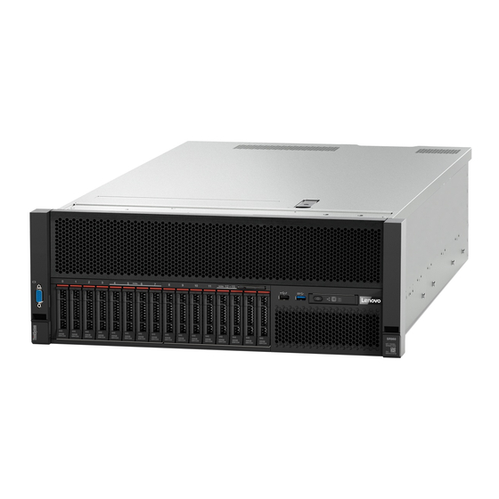
Chapter 1. Introduction The ThinkSystem SR860 is a 4U rack server designed for high-volume network transaction processing. This high-performance, multi-core server is ideally suited for networking environments that require superior processor performance, input/output (I/O) flexibility, and high manageability. Figure 1. ThinkSystem SR860 The server comes with a limited warranty. - Page 10 • 2.5-inch AnyBay 8-bay backplane (referred to as “AnyBay backplane”) 4U PCIe riser card Four types of 4U PCIe riser card: • ThinkSystem SR860 1x16 PCIe FH riser 2 • ThinkSystem SR860 2x8 PCIe FH riser 2 • ThinkSystem SR860 1x16 PCIe FH riser 3 •...
- Page 11 • Slot 1 - 2: PCI Express 3.0 for 4U PCIe riser card with the following slots available depending on the riser card installed in slot 3: – ThinkSystem SR860 2x8 PCIe FH riser 2 provides: – Slot 1: PCI Express 3.0 x8 –...
- Page 12 • One system-management RJ-45 connector on the rear to connect to a systems- management network. This connector is dedicated to the Lenovo XClarity Controller functions and runs at 1 GB speed. • Light-path diagnostics •...
-
Page 13: Firmware Updates
Note: Lenovo typically releases firmware in bundles called UpdateXpress System Packs (UXSPs). To ensure that all of the firmware updates are compatible, you should update all firmware at the same time. If you are updating firmware for both the Lenovo XClarity Controller and UEFI, update the firmware for Lenovo XClarity Controller first. - Page 14 Machine-type-specific firmware-only UXSPs are also available. See the following table to determine the best Lenovo tool to use for installing and setting up the firmware: Note: The server UEFI settings for option ROM must be set to Auto or UEFI to update firmware using Lenovo XClarity Administrator or Lenovo XClarity Essentials.
- Page 15 Additional information about using Lenovo XClarity Provisioning Manager to update firmware is available http://sysmgt.lenovofiles.com/help/topic/LXPM/platform_update.html • Lenovo XClarity Controller If you need to install a specific update, you can use the Lenovo XClarity Controller interface for a specific server. Notes: – To perform an in-band update through Windows or Linux, the operating system driver must be installed and the Ethernet-over-USB (sometimes called LAN over USB) interface must be enabled.
-
Page 16: Configuring The Lan Over Usb Interface Manually
– If you update firmware through the Lenovo XClarity Controller, make sure that you have downloaded and installed the latest device drivers for the operating system that is running on the server. Specific details about updating firmware using Lenovo XClarity Controller are available at: http://sysmgt.lenovofiles.com/help/topic/com.lenovo.systems.management.xcc.doc/NN1ia_c_... -
Page 17: Tech Tips
Tech Tips Lenovo continually updates the support website with the latest tips and techniques that you can use to solve issues that you might have with your server. These Tech Tips (also called retain tips or service bulletins) provide procedures to work around issues related to the operation of your server. -
Page 18: Power On The Server
Power off the server The server remains in a standby state when it is connected to a power source, allowing the Lenovo XClarity Controller to respond to remote power-on requests. To remove all power from the server (power status LED off), you must disconnect all power cables. -
Page 19: Chapter 2. Server Components
Use the information in this section to learn about each of the components associated with your server. Identifying your server When you contact Lenovo for help, the machine type, model, and serial number information helps support technicians to identify your server and provide faster service. -
Page 20: Front View
Network activity LED (green) Drive activity LED (green) Identification button/LED (blue) Drive status LED (yellow) System error LED (yellow) USB 1 (USB 2.0 with Lenovo XClarity Controller Front operator panel with optional pull-out LCD management) display USB 2 Rack release latches Power button/LED (green) 2.5-inch drive bays... - Page 21 Identification button/LED (blue): Press this button to visually locate the server among other servers. Use this LED to visually locate the server among other servers. You can use Lenovo XClarity Controller to turn this LED on and off. System error LED (yellow): When this yellow LED is lit, it indicates that a system error has occurred.
-
Page 22: Front Operator Panel
When this yellow LED is lit, it indicates that a system error has occurred. This LED can be controlled by the Lenovo XClarity Administrator. Information provided from the LCD display of the front operator panel could also help isolate an error. -
Page 23: Front Operator Panel With Lcd Display
Front operator panel with LCD display The following section includes an overview of the LCD system information display panel of front operator panel, which displays various types of information about the server. Depends on the configuration, your front operator panel may come with a LCD display, which is accessible with a pull on the latch on the right of the front operator panel. - Page 24 Figure 8. System information on LCD display panel Table 5. System information display panel of front operator panel System name (ThinkSystem SR860) Checkpoint code Temperature (blinking in turns with System status Power consumption (blinking in turns with The option menu UI flow on the LCD display is illustrated as following.
- Page 25 Table 6. Options available on the front operator panel Option Description System error System error provides the total number of errors the system encountered, and the description of these errors. The information is displayed as following: System Has Encountered X Errors Whereas X is the total number of system errors encountered.
- Page 26 Switch between CPU1/2 and CPU3/4 with scroll up and down buttons. • AC input voltage is displayed as following: PS1 AC Voltage: YYY V PS2 AC Voltage: YYY V • Estimated power consumption is displayed as following: Sytem Power: ZZ W Whereas ThinkSystem SR860 Maintenance Manual...
-
Page 27: Rear View
Table 6. Options available on the front operator panel (continued) • XX is the temperature. • YYY is the AC voltage. • ZZ is the wattage. Actions Actions provides the following available actions, which come in effect by pressing and holding on the select button for three seconds: •... - Page 28 NMI button System error LED (yellow) Identification button Lenovo XClarity Controller network connector AC power LED: Each hot-swap power supply comes with an AC power LED and a DC power LED. When the AC power LED is lit, it indicates that sufficient power is being supplied to the power supply through the power cord. During normal operation, both the AC and DC power LEDs are lit.
- Page 29 Identification LED (blue): Use this LED to visually locate the server among other servers. You can use Lenovo XClarity Controller to turn this LED on and off. This LED is functionally equivalent to the identification LED on the front of the server.
- Page 30 PCIe slot 1 and 2 are available with a 4U PCIe riser card installed in slot 3. Following are the 4U PCIe riser cards supported by this server. – ThinkSystem SR860 2x8 PCIe FH riser 2 provides: – Slot 1: PCI Express 3.0 x8 –...
- Page 31 PCIe slot 14 and 15 are available with a 4U PCIe riser card installed in slot 13. Following are the 4U PCIe riser cards supported by this server. – ThinkSystem SR860 2x8 PCIe FH riser 3 provides: – Slot 14: PCI Express 3.0 x8 –...
-
Page 32: System-Board Connectors
Table 8. System-board connectors PCIe slot 13, 12, 11, 10 Front operator panel connector PCIe slot 9 (LOM adapter) USB 1 (USB 2.0 with Lenovo XClarity Controller management) Backplane connector 2 PCIe slot 8 (M.2 backplane) PCIe slot 5-7 (PCIe riser card 1) -
Page 33: Switches, Jumpers, And Buttons
Switches, jumpers, and buttons The following illustrations show the location of the switches, jumpers, and buttons on the server. Note: If there is a clear protective sticker on the top of the switch block, you must remove and discard it to access the switch. -
Page 34: System-Board Leds
You can also use it to force a blue-screen memory dump (use this button only when you are directed to do so by Lenovo Support). System-board LEDs Use this information to locate the system-board LEDs. -
Page 35: Pcie Expansion Tray
System error LED (yellow) DIMM 19-24 error LED Identification LED (blue) Fan 1-6 error LED DIMM 1-6 error LED Lenovo XClarity Controller heartbeat LED (Green) FPGA heartbeat LED (Green) Processor 1 LED Light path power LED DIMM 7-18 error LED... - Page 36 PCIe expansion tray Figure 15. PCIe expansion tray Table 13. PCIe expansion tray Handle PCIe expansion tray lift point ThinkSystem SR860 Maintenance Manual...
-
Page 37: 4U Pcie Riser Assembly
4U PCIe riser assembly Use this information to locate the connectors on the optional 4U PCIe riser assembly. 1x16 PCIe full-height riser Figure 16. 1x16 PCIe full-height riser Table 14. Connector of 1x16 PCIe full-height riser One PCIe 3.0 x16 connector 2x8 PCIe full-height riser Figure 17. - Page 38 Table 17. LEDs on the optional processor and memory expansion tray Processor 3 error LED Processor 4 error LED DIMM slot 31-42 error LEDs DIMM slot 43-48 error LEDs Expansion board error LED DIMM slot 25-30 error LEDs ThinkSystem SR860 Maintenance Manual...
- Page 39 Figure 20. Connectors on the optional processor and memory expansion tray Table 18. Connectors on the optional processor and memory expansion tray NVMe signal cable connector 0-1 NVMe signal cable connector 2-3 Chapter 2 Server components...
-
Page 40: Pcie Riser Cards
Figure 22. x8/x8/x8 ML2 PCIe FH Riser Assembly Table 20. Components of x8/x8/x8 ML2 PCIe FH Riser Assembly PCIe full-height riser cage PCI Express 3.0 x8 (slot 6) PCI Express 3.0 x8 (slot 5) Customized slot for ML2 adapter (slot 7) ThinkSystem SR860 Maintenance Manual... -
Page 41: 2.5-Inch Drive Backplanes
x8/x16 ML2 PCIe FH Riser Assembly Figure 23. x8/x16 ML2 PCIe FH Riser Assembly Table 21. Components of x8/x16 ML2 PCIe FH Riser Assembly PCIe full-height riser cage Customized slot for ML2 adapter (slot 7) PCI Express 3.0 x8 (slot 5) 2.5-inch drive backplanes Use this information to locate the connectors on the optional 2.5-inch drive backplanes. -
Page 42: Raid Adapters
Use this information to locate the connectors on the optional RAID adapters. Figure 26. Connectors on SATA/SAS RAID adapter (8i) Table 24. SATA/SAS RAID adapter (8i) SATA/SAS RAID adapter (8i) with two SATA/SAS connectors (C0, C1) ThinkSystem SR860 Maintenance Manual... -
Page 43: Internal Cable Routing
Figure 27. Connectors on SATA/SAS RAID adapter (16i) Table 25. SATA/SAS RAID adapter (16i) SATA/SAS RAID adapter (16i) with four SATA/SAS connectors (C0, C1, C2, C3) Figure 28. Connectors on PCIe switch card Table 26. PCIe switch card PCIe switch card with four SATA/SAS connectors (C0, C1, C2, C3) Internal cable routing This section provides information about routing the cables when you install components in the server. - Page 44 NVMe signal cables in the cable guide and behind the tray. Figure 30. Routing the NVMe cables to the processor and memory expansion tray Connect the direct NVMe signal cables to the NVMe connectors on the processor and memory expansion tray. ThinkSystem SR860 Maintenance Manual...
- Page 45 Figure 31. Connecting the NVMe cables to the processor and memory expansion tray Before starting cable routing for 2.5-inch drives: 1. Remove the fan cage assembly (see “Remove the fan cage assembly” on page 71). 2. Remove the system board air baffle (see “Remove the system board air baffle and the power interposer” on page 128) or the processor and memory expansion tray and the processor and memory expansion tray air baffle (see “Remove the processor and memory expansion tray”...
-
Page 46: Cable Routing For 2.5-Inch Drives To One Backplane
– “One 8-bay backplane” on page 39 – “One AnyBay backplane” on page 40 – Two processors installed – Four processors installed Connecting signal cables to one backplane When there is one backplane installed, see the following illustrations for cable routing. ThinkSystem SR860 Maintenance Manual... - Page 47 One 8-bay backplane Figure 33. Cable routing, 8-bay backplane Table 29. Cables and adapters for routing SATA/SAS RAID adapter (8i) SATA/SAS signal cables (720 mm) Chapter 2 Server components...
- Page 48 Figure 34. Cable routing, AnyBay backplane with two processors installed Table 30. Cables and adapters for routing PCIe switch card NVMe signal cables for PCIe switch card SATA/SAS RAID adapter (8i) SATA/SAS signal cables (720 mm) ThinkSystem SR860 Maintenance Manual...
-
Page 49: Cable Routing For 2.5-Inch Drives To Two Backplanes
Four processors installed Figure 35. Cable routing, AnyBay backplane Note: Install the processor and memory expansion tray before connecting the signal cables to NVMe connector on the expansion tray. Table 31. Cables and adapters for routing SATA/SAS RAID adapter (8i) Direct NVMe signal cables for processor and memory expansion tray NVMe connectors on the processor and memory... - Page 50 – Four processors installed – “AnyBay backplane + AnyBay backplane” on page 49 – Two processors installed – Four processors installed ThinkSystem SR860 Maintenance Manual...
- Page 51 Connecting signal cables to two backplanes When there are two backplanes installed, see the following illustrations for cable routing. 8-bay backplane + 8-bay backplane Two options are available for this combination: 1. With SATA/SAS RAID adapter (16i) Figure 36. Cable routing, 8-bay backplane + 8-bay backplane Table 32.
- Page 52 2. With SATA/SAS RAID adapter (8i) Figure 37. Cable routing, 8-bay backplane + 8-bay backplane Table 33. Cables and adapters for routing SATA/SAS RAID adapter (8i) SATA/SAS signal cables (720 mm) SATA/SAS RAID adapter (8i) SATA/SAS signal cables (720 mm) ThinkSystem SR860 Maintenance Manual...
- Page 53 AnyBay backplane + 8-bay backplane Two processors installed Two options are available for this combination: Attention: When installing a AnyBay backplane and a 8-bay backplane, always install the AnyBay backplane to drive bay 0-7, and the 8-bay backplane to drive bay 8-15. 1.
- Page 54 Figure 39. Cable routing, AnyBay backplane + 8-bay backplane Table 35. Cables and adapters for routing PCIe switch card SATA/SAS signal cables (720 mm) SATA/SAS RAID adapter (8i) NVMe signal cables for PCIe switch card SATA/SAS RAID adapter (8i) SATA/SAS signal cables (720 mm) ThinkSystem SR860 Maintenance Manual...
- Page 55 Four processors installed Two options are available for this combination: Notes: • When installing a AnyBay backplane and a 8-bay backplane, always install the AnyBay backplane to drive bay 0-7, and the 8-bay backplane to drive bay 8-15. • Install the processor and memory expansion tray before connecting the signal cables to NVMe connector on the expansion tray.
- Page 56 Direct NVMe signal cables for processor and SATA/SAS RAID adapter (8i) memory expansion tray NVMe connectors on the processor and memory SATA/SAS signal cables (720 mm) expansion tray SATA/SAS RAID adapter (8i) SATA/SAS signal cables (720 mm) ThinkSystem SR860 Maintenance Manual...
- Page 57 AnyBay backplane + AnyBay backplane Two processors installed Two options are available for this combination: 1. With SATA/SAS RAID adapter (16i) Figure 42. Cable routing, AnyBay backplane + AnyBay backplane Table 38. Cables and adapters for routing PCIe switch card NVMe signal cables for PCIe switch card SATA/SAS RAID adapter (16i) NVMe signal cables for PCIe switch card...
- Page 58 PCIe switch card SATA/SAS signal cables (720 mm) SATA/SAS RAID adapter (8i) NVMe signal cables for PCIe switch card SATA/SAS RAID adapter (8i) NVMe signal cables for PCIe switch card PCIe switch card SATA/SAS signal cables (720 mm) ThinkSystem SR860 Maintenance Manual...
- Page 59 Four processors installed Four options are available for this combination: Note: Install the processor and memory expansion tray before connecting the signal cables to NVMe connector on the expansion tray. 1. With SATA/SAS RAID adapter (16i) Figure 44. Cable routing, AnyBay backplane + AnyBay backplane Table 40.
- Page 60 NVMe signal cables for PCIe switch card NVMe connectors on the processor and memory SATA/SAS signal cables (720 mm) expansion tray Direct NVMe signal cables for processor and SATA/SAS signal cables (900 mm) memory expansion tray ThinkSystem SR860 Maintenance Manual...
- Page 61 3. With SATA/SAS RAID adapter (8i) Figure 46. Cable routing, AnyBay backplane + AnyBay backplane Table 42. Cables and adapters for routing PCIe switch card Direct NVMe signal cables for processor and memory expansion tray SATA/SAS RAID adapter (8i) SATA/SAS signal cables (720 mm) NVMe connectors on the processor and memory SATA/SAS signal cables (720 mm) expansion tray...
-
Page 62: Parts List
Use the parts list to identify each of the components that are available for your server. For more information about ordering the parts shown in Figure 48 “Server components” on page 55: https://datacentersupport.lenovo.com/products/servers/thinksystem/sr860 Note: Depending on the model, your server might look slightly different from the illustration. ThinkSystem SR860 Maintenance Manual... - Page 63 Figure 48. Server components Chapter 2 Server components...
- Page 64 Tier 1 CRU at your request with no service agreement, you will be charged for the installation. • Tier 2 customer replaceable unit: You may install a Tier 2 CRU yourself or request Lenovo to install it, at no additional charge, under the type of warranty service that is designated for your server.
- Page 65 Table 44. Parts listing (continued) Index Description Tier 1 CRU Tier 2 CRU Consuma- ble and Structural part Processor √ Heatsink √ Fan cage √ √ 2.5-inch SATA/SAS 8-bay backplane √ 2.5-inch AnyBay (SATA/SAS/NVMe) 8-bay √ backplane Chassis air baffle √...
-
Page 66: Power Cords
The cord set should have the appropriate safety approvals for the country in which the equipment will be installed. • Power cords for a specific country or region are usually available only in that country or region. ThinkSystem SR860 Maintenance Manual... -
Page 67: Chapter 3. Hardware Replacement Procedures
Go to to download firmware updates for your server. ThinkSystem SR860 Drivers and Software Important: Some cluster solutions require specific code levels or coordinated code updates. If the component is part of a cluster solution, verify that the latest level of code is supported for the cluster solution before you update the code. -
Page 68: System Reliability Guidelines
Operating the server with a missing air baffle might damage the processor. • All processor sockets must contain either a socket cover or a processor with heat sink. • When more than one processor is installed, fan population rules for each server must be strictly followed. ThinkSystem SR860 Maintenance Manual... -
Page 69: Handling Static-Sensitive Devices
Handling static-sensitive devices Review these guidelines before you handle static-sensitive devices to reduce the possibility of damage from electrostatic discharge. Attention: Prevent exposure to static electricity, which might lead to system halt and loss of data, by keeping static-sensitive components in their static-protective packages until installation, and handling these devices with an electrostatic-discharge wrist strap or other grounding system. - Page 70 Align the tabs on the bottom of the drive backplane with the slots on the system board, and insert them into the slots. Step 2. Push the top of the drive backplane toward the front of the server until it clicks in place. ThinkSystem SR860 Maintenance Manual...
- Page 71 Figure 50. Drive backplane installation After installing the drive backplane, complete the following steps: 1. Connect the cables to the drive backplane. 2. Install the drives (see “Install a 2.5-inch hot-swap drive” on page 64). 3. Install the chassis air baffle (see “Install the chassis air baffle” on page 66). 4.
- Page 72 • Youku: http://v.youku.com/v_show/id_XMzMyODU3NTY2NA==.html?spm=a2hzp.8253876.0.0&f=51276390 Step 1. If new drives are to be added, see “Install a 2.5-inch drive” in ThinkSystem SR860 Setup Guide to determine available drive bays to the new drives. Step 2. Gently rotate the release latch away to unlock the drive handle.
-
Page 73: Chassis Air Baffle Replacement
Figure 52. Drive installation Step 4. Rotate the drive-tray handle back to the locked position. After installing the 2.5-inch hot-swap drive, check the drive status LED to verify if the drive is operating correctly: • If the yellow LED is lit continuously, it is malfunctioning and must be replaced. •... - Page 74 1. Read the safety information and installation guidelines (see “Safety” on page iii and “Installation Guidelines” on page 59). To install the chassis air baffle, complete the following steps: Watch the procedure. A video of the process is available: • Youtube: https://www.youtube.com/watch?v=pIb0bIyfkDY&=PLYV5R7hVcs-Ak9fT8QAx8fLbEivizjRtp • Youku: http://v.youku.com/v_show/id_XMzMyODU3NTY2NA==.html?spm=a2hzp.8253876.0.0&f=51276390 ThinkSystem SR860 Maintenance Manual...
-
Page 75: Cmos Battery - Cr2032 Replacement
The following notes describe information that you must consider when replacing the battery: • Lenovo has designed this product with your safety in mind. The lithium battery must be handled correctly to avoid possible danger. If you replace the battery, you must adhere to the following instructions. - Page 76 S004 CAUTION: When replacing the lithium battery, use only Lenovo specified part number or an equivalent type battery recommended by the manufacturer. If your system has a module containing a lithium battery, replace it only with the same module type made by the same manufacturer. The battery contains lithium and can explode if not properly used, handled, or disposed of.
- Page 77 Figure 55. CMOS battery location on the system board Table 46. CMOS battery CMOS battery - CR2032 To remove the CMOS battery, complete the following steps: Watch the procedure. A video of the process is available: • Youtube: https://www.youtube.com/watch?v=pIb0bIyfkDY&=PLYV5R7hVcs-Ak9fT8QAx8fLbEivizjRtp • Youku: http://v.youku.com/v_show/id_XMzMyODU3NTY2NA==.html?spm=a2hzp.8253876.0.0&f=51276390 Step 1.
- Page 78 S004 CAUTION: When replacing the lithium battery, use only Lenovo specified part number or an equivalent type battery recommended by the manufacturer. If your system has a module containing a lithium battery, replace it only with the same module type made by the same manufacturer. The battery contains lithium and can explode if not properly used, handled, or disposed of.
-
Page 79: Fan And Fan Cage Replacement
1. Read the safety information and installation guidelines (see “Safety” on page iii and “Installation Guidelines” on page 59). 2. Touch the static-protective package that contains the component to any unpainted metal surface on the server; then, remove it from the package and place it on a static-protective surface. To install the CMOS battery, complete the following steps: Watch the procedure. - Page 80 5. Remove the chassis air baffle (see “Remove the chassis air baffle” on page 65). To remove the fan cage assembly, complete the following steps: Watch the procedure. A video of the process is available: • Youtube: https://www.youtube.com/watch?v=pIb0bIyfkDY&=PLYV5R7hVcs-Ak9fT8QAx8fLbEivizjRtp • Youku: http://v.youku.com/v_show/id_XMzMyODU3NTY2NA==.html?spm=a2hzp.8253876.0.0&f=51276390 Figure 58. Fan cage assembly removal ThinkSystem SR860 Maintenance Manual...
- Page 81 Step 1. Lift and rotate the fan cage release latches to disengage the fan cage assembly from the server. Step 2. Lift the fan cage assembly from the server. If you are instructed to return the component or optional device, follow all packaging instructions, and use any packaging materials for shipping that are supplied to you.
- Page 82 4. Remove the chassis air baffle (see “Remove the chassis air baffle” on page 65). To remove a fan, complete the following steps: Watch the procedure. A video of the process is available: • Youtube: https://www.youtube.com/watch?v=pIb0bIyfkDY&=PLYV5R7hVcs-Ak9fT8QAx8fLbEivizjRtp • Youku: http://v.youku.com/v_show/id_XMzMyODU3NTY2NA==.html?spm=a2hzp.8253876.0.0&f=51276390 ThinkSystem SR860 Maintenance Manual...
- Page 83 Figure 60. Fan removal Step 1. Pinch on the top of the fan, and press on the latch to release the fan from the connector. Step 2. Lift the fan out from the fan cage. If you are instructed to return the component or optional device, follow all packaging instructions, and use any packaging materials for shipping that are supplied to you.
-
Page 84: Front Vga Assembly Replacement
3. If the server is installed in a rack, reinstall the server into the rack. Front VGA assembly replacement Use this procedure to remove or install the front VGA assembly. Remove the front VGA assembly Use this procedure to remove the front VGA assembly. Before removing the front VGA assembly: ThinkSystem SR860 Maintenance Manual... - Page 85 1. Read the safety information and installation guidelines (see “Safety” on page iii and “Installation Guidelines” on page 59). 2. Turn off the server and peripheral devices and disconnect the power cords and all external cables (see “Power off the server” on page 10). 3.
- Page 86 Watch the procedure. A video of the process is available: • Youtube: https://www.youtube.com/watch?v=pIb0bIyfkDY&=PLYV5R7hVcs-Ak9fT8QAx8fLbEivizjRtp • Youku: http://v.youku.com/v_show/id_XMzMyODU3NTY2NA==.html?spm=a2hzp.8253876.0.0&f=51276390 Step 1. Remove the fan cage assembly (see “Remove the fan cage assembly” on page 71). Step 2. Route the cable into the slot. ThinkSystem SR860 Maintenance Manual...
- Page 87 Figure 65. Front VGA assembly installation Step 3. Slide the front VGA assembly into place. Make sure the screw holes on the front VGA assembly and chassis align with each other. Figure 66. Front VGA assembly installation Step 4. Fasten the screws. Figure 67.
-
Page 88: Lom Adapter Replacement
5. Remove the PCIe expansion tray (see “Remove the PCIe expansion tray” on page 149). To remove the LOM adapter, complete the following steps: Watch the procedure. A video of the process is available: • Youtube: https://www.youtube.com/watch?v=pIb0bIyfkDY&=PLYV5R7hVcs-Ak9fT8QAx8fLbEivizjRtp • Youku: http://v.youku.com/v_show/id_XMzMyODU3NTY2NA==.html?spm=a2hzp.8253876.0.0&f=51276390 ThinkSystem SR860 Maintenance Manual... - Page 89 Figure 69. LOM adapter removal Step 1. Loosen the captive thumbscrew. Step 2. Open the retention latch. Step 3. Carefully grasp the adapter and pull it out from the connector. Step 4. Close the retention latch. If you are instructed to return the component or optional device, follow all packaging instructions, and use any packaging materials for shipping that are supplied to you.
- Page 90 Step 2. Align the LOM adapter to the connector, and push it in. Step 3. Tighten the captive thumbscrew to lock it to the connector. Figure 71. LOM adapter installation Step 4. Close the retention latch. ThinkSystem SR860 Maintenance Manual...
-
Page 91: M.2 Drive And Backplane Replacement
After installing the LOM adapter, complete the following steps: 1. Install the PCIe expansion tray (see “Install the PCIe expansion tray” on page 151). 2. Install the top cover (see “Install the top cover” on page 148). 3. Reconnect the power cords and any cables that you removed. 4. - Page 92 Step 1. Remove the M.2 backplane from the system board by pulling up on both ends of the backplane at the same time. Note: Pull the M.2 backplane straight up when removing it from the system board. ThinkSystem SR860 Maintenance Manual...
- Page 93 Figure 74. M.2 backplane removal To remove an M.2 drive from the M.2 backplane, see “Remove an M.2 drive from the M.2 backplane” on page 87. If you are instructed to return the component or optional device, follow all packaging instructions, and use any packaging materials for shipping that are supplied to you.
- Page 94 3. Install the PCIe expansion tray (see “Install the PCIe expansion tray” on page 151). 4. Install the top cover (see “Install the top cover” on page 148). 5. Reconnect the power cords and any cables that you removed. ThinkSystem SR860 Maintenance Manual...
- Page 95 6. If the server is installed in a rack, reinstall the server into the rack. 7. Power on the server and any peripheral devices. Remove an M.2 drive from the M.2 backplane Use this procedure to remove an M.2 drive from the M.2 backplane. With M.2 backplane removed, complete the following steps to remove an M.2 drive from the M.2 backplane: Watch the procedure.
- Page 96 Figure 79. M.2 drive installation Attention: When sliding the retainer forward, make sure the two nubs on the retainer enter the small holes on the M.2 backplane. Once they enter the holes, you will hear a soft “click” sound. ThinkSystem SR860 Maintenance Manual...
-
Page 97: Memory Module Replacement
Figure 80. M.2 drive installation with the retainers in place After installing an M.2 drive in the M.2 backplane, see “Install the M.2 backplane” on page 85 to complete installation. Memory module replacement Use this procedure to remove or install a memory module. Remove a memory module Use this procedure to remove a memory module. - Page 98 5. Remove the PCIe expansion tray (see “Remove the PCIe expansion tray” on page 149). 6. If you are not replacing the memory module that you removed, see the ThinkSystem SR860 Memory Population Reference for the required installation order of the remaining memory modules.
- Page 99 • Never touch the gold memory module connector contacts or allow these contacts to touch the outside of the memory-module connector housing. • Handle memory modules with care: never bend, twist, or drop a memory module. Before installing a memory module: 1.
-
Page 100: Operator Panel Tray Assembly And Front Operator Panel Replacement
Figure 83. USB 2.0 cable and front operator panel cable Table 48. USB 2.0 cable and front operator panel cable USB 2.0 cable Front operator panel cable Note: Make sure the USB 3.0 connector stays vertical when being removed from the system board. ThinkSystem SR860 Maintenance Manual... - Page 101 Figure 84. Removing USB 3.0 connector vertically Step 3. Remove the USB 3.0 cable from the cable guide. Step 4. Loosen the screw that secures the tray assembly. Step 5. Push the tray assembly slightly out of the server; then; grasp it from the front and pull it out from the server.
- Page 102 Figure 87. USB 2.0 cable and front operator panel cable Table 49. USB 2.0 cable and front operator panel cable USB 2.0 cable Front operator panel cable After installing the operator panel tray assembly, complete the following steps: ThinkSystem SR860 Maintenance Manual...
- Page 103 1. Reconnect the USB 3.0 cable of operator panel tray assembly vertically to the system board. Figure 88. Installing USB 3.0 connector vertically Route the USB 3.0 cable in the cable guide and away from the PCIe slots area (marked in gray). Figure 89.
- Page 104 2. Touch the static-protective package that contains the component to any unpainted metal surface on the server; then, remove it from the package and place it on a static-protective surface. To install the front operator panel, complete the following steps: ThinkSystem SR860 Maintenance Manual...
-
Page 105: Pcie Riser Card Assembly And Adapter Replacement
Watch the procedure. A video of the process is available: • Youtube: https://www.youtube.com/watch?v=pIb0bIyfkDY&=PLYV5R7hVcs-Ak9fT8QAx8fLbEivizjRtp • Youku: http://v.youku.com/v_show/id_XMzMyODU3NTY2NA==.html?spm=a2hzp.8253876.0.0&f=51276390 Step 1. Align the panel with the slot on operator panel tray assembly, and slide it in until it clicks into place. Figure 91. Front operator panel installation After installing operator panel tray assembly, complete the following steps: 1. - Page 106 Grasp the PCIe riser card assembly at the touch-points, and lift it out from the system board. Figure 93. PCIe riser card assembly removal Step 3. Remove the screws that fix the PCIe riser card, and slightly push it away to detach it from the riser- cage. ThinkSystem SR860 Maintenance Manual...
- Page 107 Figure 94. PCIe riser card removal If you are instructed to return the component or optional device, follow all packaging instructions, and use any packaging materials for shipping that are supplied to you. Install the PCIe riser card assembly Use this procedure to install the PCIe riser card assembly. Before installing the PCIe riser card assembly: 1.
- Page 108 Install the PCIe riser card to the riser cage with screws. Figure 97. PCIe riser card assembly Step 2. Align the PCIe riser card assembly with the connector on the system board; then, push it in until it clicks in place. ThinkSystem SR860 Maintenance Manual...
- Page 109 Figure 98. PCIe riser card assembly installation Step 3. Reconnect all the cables disconnected previously. After installing the PCIe riser card assembly, complete the following steps: 1. Reconnect the USB 3.0 cable of operator panel tray assembly vertically to the system board. Figure 99.
- Page 110 1. Read the safety information and installation guidelines (see “Safety” on page iii and “Installation Guidelines” on page 59). 2. Turn off the server and peripheral devices and disconnect the power cords and all external cables (see “Power off the server” on page 10). ThinkSystem SR860 Maintenance Manual...
- Page 111 3. If the server is installed in a rack, remove the server from the rack. 4. Remove the top cover (see “Remove the top cover” on page 146). 5. Remove the PCIe expansion tray (see “Remove the PCIe expansion tray” on page 149). Remove an adapter from the system board To remove an adapter from the system board, complete the following steps: Watch the procedure.
- Page 112 Step 1. Open the retention latch. Step 2. Align the adapter with the connector on the system board. Notes: Use specific PCIe slots for the following RAID adapters: • RAID adapter for SATA/SAS drives: slot 2, 10 ThinkSystem SR860 Maintenance Manual...
- Page 113 • PCIe switch card: slot 1, 11 For PCIe slot numbering, see “System-board connectors” on page 24. Step 3. Push the adapter in until it clicks into place. Figure 103. Adapter installation to the system board Step 4. Connect internal cables to the adapter. Follow instructions of internal cable routing for adapters (see “Internal cable routing”...
-
Page 114: Power Supply Unit Replacement
The power control button on the device and the power switch on the power supply do not turn off the electrical current that is supplied to the device. The device also might have more than one power ThinkSystem SR860 Maintenance Manual... - Page 115 cord. To remove all electrical current from the device, ensure that all power cords are disconnected from the power source. S029 DANGER Electrical current from power, telephone, and communication cables is hazardous. To avoid a shock hazard: • Do not connect or disconnect any cables or perform installation, maintenance, or reconfiguration of this product during an electrical storm.
- Page 116 If you are instructed to return the component or optional device, follow all packaging instructions, and use any packaging materials for shipping that are supplied to you. Install a hot-swap power supply unit Use this procedure to install a hot-swap power supply unit. S002 ThinkSystem SR860 Maintenance Manual...
- Page 117 CAUTION: The power control button on the device and the power switch on the power supply do not turn off the electrical current that is supplied to the device. The device also might have more than one power cord. To remove all electrical current from the device, ensure that all power cords are disconnected from the power source.
- Page 118 If you are installing the power supply into an empty bay, remove the power-supply filler panel from the power-supply bay. Step 2. Grasp the handle on the rear of the power supply, and slide it into the power-supply bay until it clicks into place. ThinkSystem SR860 Maintenance Manual...
- Page 119 Figure 106. Power supply unit installation Notes: • Pull the handle to try if the power supply unit is properly installed. If it slides out, reinstall it. • Power supply 1 is on the bottom, while power supply 2 is on the top. For more details, see “Rear view”...
-
Page 120: Processor And Heat Sink Replacement
5. Remove the system board air baffle (see “Remove the system board air baffle and the power interposer” on page 128) or the processor and memory expansion tray and the processor and memory expansion tray air baffle (see “Remove the processor and memory expansion tray” on page 122). ThinkSystem SR860 Maintenance Manual... - Page 121 Figure 107. Processor locations Table 50. Processor locations Processor 3 Processor 1 Processor 4 Processor 2 Complete the following steps to remove a PHM. Watch the procedure. A video of the process is available: • Youtube: https://www.youtube.com/watch?v=pIb0bIyfkDY&=PLYV5R7hVcs-Ak9fT8QAx8fLbEivizjRtp • Youku: http://v.youku.com/v_show/id_XMzMyODU3NTY2NA==.html?spm=a2hzp.8253876.0.0&f=51276390 Step 1.
- Page 122 • If you are removing the PHM as part of a system board replacement, set the PHM aside. • If you are replacing the processor or heat sink, separate the processor and its retainer from the heat sink. ThinkSystem SR860 Maintenance Manual...
- Page 123 Figure 109. Separating a heat sink from a processor 1. Press the retaining clip at the corner of the processor retainer closest to the pry point; then, gently pry this corner of the retainer away from the heat sink with a flat-bladed screwdriver, using a twisting motion to break the processor-to-heat-sink seal.
- Page 124 • Before you install a new PHM or replacement processor, update your system firmware to the latest level. See “Update the firmware” in the ThinkSystem SR860 Setup Guide. • Installing an additional PHM can change the memory requirements for your system. See ThinkSystem SR860 Memory Population Reference for a list of processor-to-memory relationships.
- Page 125 Figure 110. Removing a processor retainer Note: When the processor is out of its retainer, hold the processor by the long edges to prevent touching the contacts or the thermal grease, if it is applied. With the processor-contact side up, flex the ends of the retainer down and away from the processor to release the retaining clips;...
- Page 126 To prevent the processor from falling out of the retainer, hold the processor-retainer assembly by its sides with the processor-contact side up until you turn it over to fit in the shipping tray. ThinkSystem SR860 Maintenance Manual...
- Page 127 Figure 113. Assembling a PHM in the shipping tray a. Align the triangular marks on the processor retainer and the heat sink or align the triangular mark on the processor retainer with the notched corner of the heat sink. b. Insert the processor-retainer clips into the holes on the heat sink. c.
- Page 128 Remove the processor socket cover, if one is installed on the processor socket, by placing your fingers in the half-circles at each end of the cover and lifting it from the system board. Step 2. Install the processor-heat-sink module on the system board. ThinkSystem SR860 Maintenance Manual...
-
Page 129: Processor And Memory Expansion Tray Replacement
Figure 115. Installing a PHM Align the triangular marks and guide pins on the processor socket with the PHM; then, insert the PHM into the processor socket. Attention: To prevent damage to components, make sure that you follow the indicated tightening sequence. - Page 130 Step 1. Disconnect all cables connected to the processor and memory expansion tray. Step 2. Slightly pull out power supply 2. Attention: Do not remove the processor and memory expansion tray without physically disconnecting power supply 2. ThinkSystem SR860 Maintenance Manual...
- Page 131 Step 3. Grasp the handle of the processor and memory expansion tray; then, pull and rotate it upward to the vertical position. This disengages the expansion tray from the system board. Step 4. Grasp the handle and slowly lift the expansion tray from the server; then, set it on a flat surface. Figure 117.
- Page 132 Grip on the blue touch point on the handle of the expansion tray, and lift it up; then, lower the tray vertically into the server with nailheads aligned to the slots on both sides. Step 5. Rotate the handle down to make sure the expansion tray is fully seated into the system board. ThinkSystem SR860 Maintenance Manual...
- Page 133 Figure 119. Processor and memory expansion tray installation Step 6. Install DIMMs (see “Install a memory module” on page 90), PHMs (see “Install a processor and heat sink” on page 116), and another processor and memory expansion tray air baffle on the expansion tray.
-
Page 134: Security Bezel Replacement
2. If the server is installed in a rack, extend or remove the server from the rack. To remove the security bezel, complete the following steps: Watch the procedure. A video of the process is available: • Youtube: https://www.youtube.com/watch?v=pIb0bIyfkDY&=PLYV5R7hVcs-Ak9fT8QAx8fLbEivizjRtp • Youku: http://v.youku.com/v_show/id_XMzMyODU3NTY2NA==.html?spm=a2hzp.8253876.0.0&f=51276390 ThinkSystem SR860 Maintenance Manual... - Page 135 1. Read the safety information and installation guidelines (see “Safety” on page iii and “Installation Guidelines” on page 59). 2. If you have removed the rack handles, reinstall it (see ThinkSystem SR860 Rack Installation Guide). To install the security bezel, complete the following steps: Watch the procedure.
-
Page 136: System Board Air Baffle And The Power Interposer Replacement
Use this procedure to remove the system board air baffle and the power interposer. Note: If the server comes with a processor and memory expansion tray, it does not come with this component. Before removing the system board air baffle, complete the following steps: ThinkSystem SR860 Maintenance Manual... - Page 137 1. Read the safety information and installation guidelines (see “Safety” on page iii and “Installation Guidelines” on page 59). 2. Turn off the server and peripheral devices and disconnect the power cords and all external cables (see “Power off the server” on page 10). 3.
- Page 138 Slightly slide power supply 2 out from the power supply bay (see “Remove a hot-swap power supply unit” on page 106). Step 2. Align the power interposer to the server, and lower it until it sits firmly in place. ThinkSystem SR860 Maintenance Manual...
- Page 139 Figure 127. Power interposer installation Step 3. Align the two pairs of nailheads of the system board air baffle to slots, and lower it into the server. Attention: Air baffle is required for airflow that creates proper cooling. Make sure proper air baffle (s) for system configuration is installed before the power is turned on.
-
Page 140: System Board Replacement
Universally Unique Identifier, and asset tag of the server. 2. Use the Lenovo XClarity Essentials OneCLI to save the system configuration to external media. 3. Save the system-event log to external media. - Page 141 (see “Remove a memory module” on page 89). Note: Make a note of the location of all the installed DIMMs for later reference. Refer to ThinkSystem SR860 Memory Population Reference if you’re adding more DIMMs. Step 8. Remove the PCIe riser card if it has been installed (see “Remove the PCIe riser card assembly” on page 97).
- Page 142 Note: This handle only serves the purpose of removing system board. Do not attempt to lift the whole server with it. If you are instructed to return the component or optional device, follow all packaging instructions, and use any packaging materials for shipping that are supplied to you. ThinkSystem SR860 Maintenance Manual...
- Page 143 Important: Before you return the system board, make sure that you install the CPU socket covers from the new system board. To replace a CPU socket cover: 1. Take a socket cover from the CPU socket assembly on the new system board and orient it correctly above the CPU socket assembly on the removed system board.
- Page 144 6. Optionally, enable Secure Boot. Update the Universal Unique Identifier (UUID) The Universal Unique Identifier (UUID) must be updated when the system board is replaced. Use the Lenovo XClarity Essentials OneCLI to update the UUID in the UEFI-based solution. Lenovo XClarity Essentials OneCLI is an online tool that supports several operating systems;...
- Page 145 Lenovo XClarity Essentials OneCLI sets the UUID in the Lenovo XClarity Controller. Select one of the following methods to access the Lenovo XClarity Controller and set the UUID: • Online from the target system, such as LAN or keyboard console style (KCS) access •...
- Page 146 To download Lenovo XClarity Essentials OneCLI, go to the following site: https://datacentersupport.lenovo.com/solutions/HT116433 Lenovo XClarity Essentials OneCLI sets the DMI in the Lenovo XClarity Controller. Select one of the following methods to access the Lenovo XClarity Controller and set the DMI: •...
- Page 147 2. If you do not specify any of these parameters, OneCLI will use the default values. When the default values are used and OneCLI is unable to access the Lenovo XClarity Controller using the online authenticated LAN access method, OneCLI will automatically use the unauthenticated KCS access method.
- Page 148 Before you can assert Physical Presence, the Physical Presence Policy must be enabled. By default, the Physical Presence Policy is enabled with a timeout of 30 minutes. If the Physical Presence Policy is enabled, you can assert Physical Presence through the Lenovo XClarity Controller or through hardware jumpers on the system board.
- Page 149 (zero, not an uppercase o) • <ip_address> is the IP address of the BMC. For more information about the Lenovo XClarity Essentials OneCLI s s e e t t command, see: http://sysmgt.lenovofiles.com/help/topic/toolsctr_cli_lenovo/onecli_r_set_command.html 3. Alternatively, you can use the following Advanced Settings Utility (ASU) commands:...
- Page 150 The default user ID is USERID, and the default password is PASSW0RD (zero, not an uppercase o) – <ip_address> is the IP address of the BMC. For more information about the Lenovo XClarity Essentials OneCLI s s e e t t command, see: http://sysmgt.lenovofiles.com/help/topic/toolsctr_cli_lenovo/onecli_r_set_command.html ThinkSystem SR860 Maintenance Manual...
-
Page 151: Tcm/Tpm Adapter Replacement (For China Only)
TCM/TPM adapter replacement (for China only) Use this procedure to remove or install the TCM/TPM adapter. Remove the TCM/TPM adapter (for China only) Use this information to remove the TCM/TPM adapter. Before removing the TCM/TPM adapter: 1. Read the safety information and installation guidelines (see “Safety” on page iii and “Installation Guidelines”... - Page 152 1. Read the safety information and installation guidelines (see “Safety” on page iii and “Installation Guidelines” on page 59). 2. Touch the static-protective package that contains the component to any unpainted metal surface on the server; then, remove it from the package and place it on a static-protective surface. ThinkSystem SR860 Maintenance Manual...
- Page 153 3. Disconnect the USB 3.0 cable of operator panel tray assembly, and remove it vertically from the system board. Figure 135. Removing USB 3.0 connector vertically To install the TCM/TPM adapter, complete the following steps: Watch the procedure. A video of the process is available: •...
-
Page 154: Top Cover Replacement
2. Reconnect the power cords and any cables that you removed. 3. Power on the server and any peripheral devices. Top cover replacement Use this procedure to install or remove the top cover. Remove the top cover Use this procedure to remove the top cover. ThinkSystem SR860 Maintenance Manual... - Page 155 S014 CAUTION: Hazardous voltage, current, and energy levels might be present. Only a qualified service technician is authorized to remove the covers where the following label is attached. S033 CAUTION: Hazardous energy present. Voltages with hazardous energy might cause heating when shorted with metal, which might result in spattered metal, burns, or both.
- Page 156 Hazardous energy present. Voltages with hazardous energy might cause heating when shorted with metal, which might result in spattered metal, burns, or both. Before installing the top cover: 1. Read the safety information and installation guidelines (see “Safety” on page iii and “Installation Guidelines” on page 59). ThinkSystem SR860 Maintenance Manual...
-
Page 157: Replace Components In The Pcie Expansion Tray
2. Make sure all the removed components are installed, and all the disconnected cables are reconnected. To install the top cover, complete the following steps: Watch the procedure. A video of the process is available: • Youtube: https://www.youtube.com/watch?v=pIb0bIyfkDY&=PLYV5R7hVcs-Ak9fT8QAx8fLbEivizjRtp • Youku: http://v.youku.com/v_show/id_XMzMyODU3NTY2NA==.html?spm=a2hzp.8253876.0.0&f=51276390 Step 1. - Page 158 If you are instructed to return the component or optional device, follow all packaging instructions, and use any packaging materials for shipping that are supplied to you. ThinkSystem SR860 Maintenance Manual...
- Page 159 Install the PCIe expansion tray Use this procedure to install the PCIe expansion tray. Before installing a PCIe expansion tray: 1. Read the safety information and installation guidelines (see “Safety” on page iii and “Installation Guidelines” on page 59). To install the PCIe expansion tray, complete the following steps: Watch the procedure.
-
Page 160: 4U Pcie Riser Assembly Replacement
3. If the server is installed in a rack, remove the server from the rack. 4. Remove the top cover (see “Remove the top cover” on page 146). To remove a 4U PCIe riser assembly, complete the following steps: ThinkSystem SR860 Maintenance Manual... - Page 161 Watch the procedure. A video of the process is available: • Youtube: https://www.youtube.com/watch?v=pIb0bIyfkDY&=PLYV5R7hVcs-Ak9fT8QAx8fLbEivizjRtp • Youku: http://v.youku.com/v_show/id_XMzMyODU3NTY2NA==.html?spm=a2hzp.8253876.0.0&f=51276390 Figure 143. 4U PCIe riser assembly removal Table 53. 4U PCIe riser assembly filler 4U PCIe riser assembly filler Step 1. Open the release latch. Step 2.
- Page 162 Rotate the lever downward until it clicks. Make sure the 4U PCIe riser assembly is fully seated into the PCIe expansion tray. Note: To maintain proper system cooling, if only one 4U PCIe riser assembly is installed, the 4U PCIe riser assembly filler must be installed to operate the server. ThinkSystem SR860 Maintenance Manual...
-
Page 163: 4U Pcie Riser Card Replacement
Figure 145. 4U PCIe riser assembly installation Table 54. Guide pin and assembly filler Guide pin 4U PCIe riser assembly filler After installing a 4U PCIe riser assembly, complete the following steps: 1. Install the top cover (see “Install the top cover” on page 148). 2. - Page 164 Disconnect the power cable connected from the fan, and remove the screws. Figure 146. 4U PCIe riser card removal Step 3. Slightly slide the 4U PCIe riser card toward the fan; then, detach it from the 4U PCIe riser cage. ThinkSystem SR860 Maintenance Manual...
- Page 165 Figure 147. 4U PCIe riser card removal Table 55. Guide pin on the riser cage Guide pin If you are instructed to return the component or optional device, follow all packaging instructions, and use any packaging materials for shipping that are supplied to you. Install a 4U PCIe riser card Use this procedure to install a 4U PCIe riser card.
- Page 166 Table 56. Guide pin on the riser cage Guide pin Step 2. Fasten the screws to secure the 4U PCIe riser card to the 4U PCIe riser cage; then, connect the fan power cable to the 4U PCIe riser card. ThinkSystem SR860 Maintenance Manual...
-
Page 167: 4U Pcie Riser Power Cable Assembly Replacement
Figure 149. 4U PCIe riser card installation After installing a 4U PCIe riser card, complete the following steps: 1. Install the 4U PCIe riser assembly (see “Install a 4U PCIe riser assembly” on page 153). 2. Install the top cover (see “Install the top cover” on page 148). 3. - Page 168 Remove the processor and memory expansion tray (see “Remove the processor and memory expansion tray” on page 122). Repeat previous steps 2 and 3 to remove the 4U PCIe riser 2 power cable assembly . Figure 151. 4U PCIe riser 2 power cable assembly removal ThinkSystem SR860 Maintenance Manual...
- Page 169 If you are instructed to return the component or optional device, follow all packaging instructions, and use any packaging materials for shipping that are supplied to you. Install a 4U PCIe riser power cable assembly Use this procedure to install a 4U PCIe riser power cable assembly. Before installing a 4U PCIe riser power cable assembly: 1.
-
Page 170: Pcie Adapter Replacement
5. Remove the 4U PCIe riser assembly (see “Remove a 4U PCIe riser assembly” on page 152). Notes: • All GPUs come with a power cable, which has to be connected to the 4U PCIe riser card. ThinkSystem SR860 Maintenance Manual... - Page 171 • Some types of GPU require the total installed memory to be less than 1 TB. For specific types of GPU, see: https://support.lenovo.com/en/solutions/ht114952 • NVIDIA V100 GPU is supported only when two 2000W power supply units are installed in the server and all processors are less than 200W.
- Page 172 • NVIDIA V100 GPU is supported only when two 2000W power supply units are installed in the server and all processors are less than 200W. To install a PCIe adapter, complete the following steps: Watch the procedure. A video of the process is available: • Youtube: https://www.youtube.com/watch?v=pIb0bIyfkDY&=PLYV5R7hVcs-Ak9fT8QAx8fLbEivizjRtp ThinkSystem SR860 Maintenance Manual...
- Page 173 • Youku: http://v.youku.com/v_show/id_XMzMyODU3NTY2NA==.html?spm=a2hzp.8253876.0.0&f=51276390 Step 1. If an adapter filler is installed in the slot, remove it. Step 2. Align the PCIe adapter with the alignment slot and the connector on the 4U PCIe riser assembly; then, insert the PCIe adapter into the connector. Make sure the PCIe adapter is fully seated into the connector.
-
Page 174: Complete The Parts Replacement
• Update the system firmware. See “Firmware updates” on page 5. • Update the UEFI configuration. • Reconfigure the disk arrays if you have installed or removed a hot-swap drive or a RAID adapter. See the Lenovo XClarity Provisioning Manager User Guide, which is available for download at: http:// datacentersupport.lenovo.com... -
Page 175: Chapter 4. Problem Determination
An alert is a message or other indication that signals an event or an impending event. Alerts are generated by the Lenovo XClarity Controller or by UEFI in the servers. These alerts are stored in the Lenovo XClarity Controller Event Log. If the server is managed by the Chassis Management Module or by the Lenovo XClarity Administrator, alerts are automatically forwarded to those management applications. - Page 176 Lenovo XClarity Controller event log The Lenovo XClarity Controller monitors the physical state of the server and its components using sensors that measure internal physical variables such as temperature, power-supply voltages, fan speeds, and component status. The Lenovo XClarity Controller provides various interfaces to systems management software and to system administrators and users to enable remote management and control of a server.
-
Page 177: Light Path Diagnostics
Light path diagnostics Light path diagnostics is a system of LEDs on various external and internal components of the server that leads you to the failed component. When an error occurs, LEDs are lit on the front operator panel on the front of the server, then on the failed component. -
Page 178: Power Supply Leds
This LED is used as a presence detection Use this LED to locate the server among Identification button/ LED (blue) LED. You can use Lenovo XClarity other servers visually. Controller to light this LED remotely. System error LED LED on: An error has occurred. -
Page 179: General Problem Determination Procedures
Normal operation The server is functioning correctly. No ac power to the server, a 1. Check the ac power to problem with the ac power the server. source, or a power supply 2. Make sure that the power has failed. cord is connected to a functioning power source. -
Page 180: Resolving Suspected Power Problems
• Any external devices, • Surge-suppressor device (on the server). • Printer, mouse, and non-Lenovo devices. • Each adapter. • Hard disk drives. • Memory modules until you reach the minimum configuration that is supported for the server. -
Page 181: Troubleshooting By Symptom
1. Check the event log of the application that is managing the server and follow the suggested actions to resolve any event codes. • If you are managing the server from the Lenovo XClarity Administrator, begin with the Lenovo XClarity Administrator event log. - Page 182 Run the diagnostics tests for the hard disk drives. When you start a server and press F1, the Lenovo XClarity Provisioning Manager interface is displayed by default. You can perform hard drive diagnostics from this interface. From the Diagnostic page, click Run Diagnostic ➙...
- Page 183 Multiple drives fail Complete the following steps until the problem is solved: • View the Lenovo XClarity Controller event log for events related to power supplies or vibration issues and resolve those events. • Make sure that the device drivers and firmware for the hard disk drive and server are at the latest level...
- Page 184 A drive has failed with yellow LED lit Complete the following steps until the problem is solved: 1. Check the Lenovo XClarity Controller event log for drive events and resolve the problem. A newly installed drive is not recognized. Complete the following steps until the problem is solved: 1.
-
Page 185: Fan Problems
2. For a USB device: a. Make sure that the device is configured correctly. Restart the server and press F1 to display the Lenovo XClarity Provisioning Manager system setup interface. Then, click System Settings ➙ Devices and I/O Ports ➙ USB Configuration. -
Page 186: Keyboard, Mouse, Or Usb-Device Problems
(POST Watchdog Timer). To check the POST watchdog time, restart the server and press F1 to display the Lenovo XClarity Provisioning Manager system setup interface. Then, click BMC Settings ➙ POST Watchdog Timer. -
Page 187: Memory Problems
• If a DIMM was disabled by the user or by POST, reseat the DIMM; then, run the Setup utility and enable the DIMM. 4. Run memory diagnostics. When you start a server and press F1, the Lenovo XClarity Provisioning Manager interface is displayed by default. You can perform memory diagnostics from this interface. -
Page 188: Monitor And Video Problems
To use the management controller remote presence function, remove the optional video adapter. 3. If the server installed with the graphical adapters while turning on the server, the Lenovo logo displays on the screen after approximately 3 minutes. This is normal operation while the system loads. -
Page 189: Network Problems
To prevent diskette drive read/write errors, make sure that the distance between the monitor and any external diskette drive is at least 76 mm (3 in.). b. Non-Lenovo monitor cables might cause unpredictable problems. 2. Reseat the monitor cable. - Page 190 If the system hangs during the UEFI boot process with the message UEFI: DXE INIT on the display, make sure that Option ROMs were not configured with a setting of Legacy. You can remotely view the current settings for Option ROMs by running the following command using the Lenovo XClarity Essentials OneCLI: onecli config show EnableDisableAdapterOptionROMSupport --bmc xcc_userid:xcc_password@xcc_ipaddress...
- Page 191 You can specify the number of consecutive restart attempts in System Setup. Restart the server and press F1 to display the Lenovo XClarity Provisioning Manager system setup interface. Then, click System Settings ➙ Recovery and RAS ➙ POST Attempts ➙ POST Attempts Limit. Available options are 3, 6, 9, and disable.
-
Page 192: Optional-Device Problems
• “PCIe adapter is not recognized or is not functioning” on page 184 • “A Lenovo optional device that worked previously does not work now. ” on page 185 • “A Lenovo optional device that was just installed does not work.” on page 185 •... -
Page 193: Power On And Power Off Problems
A Lenovo optional device that was just installed does not work. 1. Make sure that: • The device is supported for the server (see http://www.lenovo.com/us/en/serverproven/ • You followed the installation instructions that came with the device and the device is installed correctly. - Page 194 Complete the following steps until the problem is resolved: 1. Determine whether you are using an Advanced Configuration and Power Interface (ACPI) or a non-ACPI operating system. If you are using a non-ACPI operating system, complete the following steps: a. Press Ctrl+Alt+Delete. ThinkSystem SR860 Maintenance Manual...
-
Page 195: Processor Problems
• “The server goes directly to the POST event viewer when it is turned on.” on page 187 The server goes directly to the POST event viewer when it is turned on. 1. Check the light path diagnostics LEDs and the Lenovo XClarity Controller event log, and resolve any errors that have occurred. -
Page 196: Software Problems
3. Check the operating system logs for any events related to your software and attempt to resolve them. 4. Contact your place of purchase of the software. ThinkSystem SR860 Maintenance Manual... -
Page 197: Appendix A. Getting Help And Technical Assistance
Appendix A. Getting help and technical assistance If you need help, service, or technical assistance or just want more information about Lenovo products, you will find a wide variety of sources available from Lenovo to assist you. On the World Wide Web, up-to-date information about Lenovo systems, optional devices, services, and support are available at: http://datacentersupport.lenovo.com... -
Page 198: Collecting Service Data
Collecting service data To clearly identify the root cause of a server issue or at the request of Lenovo Support, you might need collect service data that can be used for further analysis. Service data includes information such as event logs and hardware inventory. -
Page 199: Contacting Support
• Lenovo XClarity Essentials OneCLI Lenovo XClarity Essentials OneCLI has inventory application to collect service data. It can run both in- band and out-of-band. When running in-band within the host operating system on the server, OneCLI can collect information about the operating system, such as the operating system event log, in addition to the hardware service data. - Page 200 ThinkSystem SR860 Maintenance Manual...
-
Page 201: Appendix B. Notices
Lenovo representative for information on the products and services currently available in your area. Any reference to a Lenovo product, program, or service is not intended to state or imply that only that Lenovo product, program, or service may be used. Any functionally equivalent product, program, or service that does not infringe any Lenovo intellectual property right may be used instead. -
Page 202: Trademarks
(TBW). A device that has exceeded this limit might fail to respond to system-generated commands or might be incapable of being written to. Lenovo is not responsible for replacement of a device that has exceeded its maximum guaranteed number of program/erase cycles, as documented in the Official Published Specifications for the device. -
Page 203: Telecommunication Regulatory Statement
Lenovo may condition provision of repair or replacement of devices or parts on implementation of appropriate remedial measures to mitigate such environmental contamination. Implementation of such remedial measures is a customer responsibility. Table 58. Limits for particulates and gases... -
Page 204: Taiwan Bsmi Rohs Declaration
Taiwan BSMI RoHS declaration Taiwan import and export contact information Contacts are available for Taiwan import and export information. ThinkSystem SR860 Maintenance Manual... -
Page 205: Index
Ethernet systems-management install Lenovo XClarity Controller remove power supply fan cage serial 19, 21 install 13, 19, 21 fan cage assembly video remove front fan problems rear 19, 21 fan, fan cage connectors © Copyright Lenovo 2018... - Page 206 RAID adapter optional processor system board light path diagnostics panel system board air baffle NMI button top cover LOM adapter installation install guidelines remove installation guidelines replacement installing DIMM heat sink installing memory module replacement ThinkSystem SR860 Maintenance Manual...
- Page 207 LOM adapter replacement M.2 drive power off the server PCIe adapter 162, 164 power on the server PCIe expansion, tray power problems PCIe riser power supply PCIe riser assembly install PCIe riser cable remove power cable © Copyright Lenovo 2018...
- Page 208 19, 21 adjustment Taiwan BSMI RoHS declaration safety Taiwan import and export contact information safety inspection checklist SATA/SAS TCM policy Secure Boot TCM/TPM adapter security bezel installing installing removing removing replacement replacement telecommunication regulatory statement ThinkSystem SR860 Maintenance Manual...
- Page 209 19, 21 network problems video problems 180, 187 observable problems power on and power off problems serial-device problems symptoms-based troubleshooting USB-device problems video 180, 187 Windows driver, LAN over USB Trusted Cryptographic Module © Copyright Lenovo 2018...
- Page 210 ThinkSystem SR860 Maintenance Manual...
- Page 212 Part Number: SP47A30805 Printed in China (1P) P/N: SP47A30805 *1PSP47A30805*...