Table of Contents
Advertisement
Quick Links
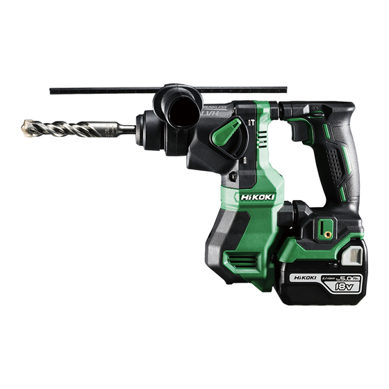
PRODUCT NAME
Cordless Rotary Hammer
Models 18 V
10.8 V
CONTENTS
REPAIR GUIDE ---------------------------------------------------------------------------------------------------------------- 1
1. Precautions on disassembly and reassembly ----------------------------------------------------------- 1
• Disassembly -------------------------------------------------------------------------------------------------- 1
• Reassembly -------------------------------------------------------------------------------------------------- 4
• Checking after reassembly ----------------------------------------------------------------------------- 12
• Tightening torque ------------------------------------------------------------------------------------------ 12
• No-load current -------------------------------------------------------------------------------------------- 12
• Lubrication points and types of lubricant ------------------------------------------------------------ 13
• Wiring diagram --------------------------------------------------------------------------------------------- 16
2. Precautions on disassembly and reassembly of the charger ---------------------------------------- 17
DH 18DPA
DH 18DPA
DH 12DD
CONFIDENTIAL
DH 12DD
Overseas Sales Management Dept.
Jan. 2021
D
Page
Advertisement
Table of Contents

Related Manuals for Hitachi DH 18DPA


Summary of Contents for Hitachi DH 18DPA
-
Page 1: Table Of Contents
CONFIDENTIAL Jan. 2021 PRODUCT NAME Cordless Rotary Hammer DH 18DPA Models 18 V DH 12DD 10.8 V CONTENTS Page REPAIR GUIDE ---------------------------------------------------------------------------------------------------------------- 1 1. Precautions on disassembly and reassembly ----------------------------------------------------------- 1 • Disassembly -------------------------------------------------------------------------------------------------- 1 • Reassembly -------------------------------------------------------------------------------------------------- 4 • Checking after reassembly ----------------------------------------------------------------------------- 12 •... -
Page 2: Repair Guide
1. Precautions on disassembly and reassembly [Bold] numbers in the description below correspond to the item numbers in the parts list and exploded assembly diagram for the Model DH 18DPA and {Bold} numbers to those for the Model DH 12DD. Disassembly 1. - Page 3 2. Disassembly of the hammering mechanism (1) Removal of the gear cover Set the Change Lever [11]{11} to the "Rotation + Hammering" ( mark) position. Remove the four Tapping Screws (W/Flange) D4 x 30 (Black) [8]{8} to remove the Gear Cover [9]{9}. (2) Disassembly of inner cover (B) ass’y Remove the two Seal Lock Hex.
- Page 4 3. Disassembly of the cylinder assembly (1) Disassembly of the slip clutch ass’y Remove the Machine Screw M4 x 5 [14]{14} that fixes the Change Lever [11]{11} and Stopper [13]{13} in the Gear Cover [9]{9}. Pull out the Change Lever [11]{11} and Stopper [13]{13} from the Gear Cover [9]{9}.
-
Page 5: Reassembly
Reassembly Reassembly can generally be conducted by reversing the disassembly procedure. However, special attention should be given to the following items. 1. Reassembly of the cylinder ass’y NOTE: Use the special repair tool specified in the Special repair tool Code No. table for mounting the parts to the inside J-407 Stopper ring jig... - Page 6 2. Reassembly of the gear cover and cylinder ass’y (1) Mount the Second Gear [18]{18}, Spring (A) [17]{17}, and Washer [16]{16} on the Cylinder [20]{20} ass’y and fix them with the Retaining Ring for D25 Shaft [15]{15}. Mount the Damper [26]{26}, Thrust Washer (A) [27]{27}, and Thrust Washer (B) [28]{28} from the rear end of the Cylinder [20]{20}.
- Page 7 3. Reassembly of the second shaft ass’y NOTE: Use the special repair tool specified in the Special repair tool Code No. table for reassembly of the second shaft J-408 Bevel gear jig 376748 ass’y. (1) Mount the Clutch [44]{44}, Reciprocating Bearing [45]{45}, Needle Cage [46]{46}, and Thrust Washer (C) [47]{47} on Second Shaft (A) [43]{43}.
- Page 8 4. Reassembly of the hammering mechanism NOTE: Degrease the M5 screw hole on Inner Cover (A) Ass’y [49]{49} using the parts cleaner before reassembly of the hammering mechanism. Otherwise, the screw may be loosened and it may cause troubles. (1) Mount O-ring (A) [30]{30} to the Striker [29]{29} and push it in the Piston [31]{31} as shown in Fig. 9. Mount the two Washers [42]{42} to the Piston [31]{31} and insert the Piston Pin [41]{41} into the Piston [31]{31}.
- Page 9 5. Reassembly of the gear cover ass’y (1) After mounting the hammering mechanism to Inner Cover (A) Ass’y [49]{49}, insert Spring (B) [33]{33} into the tip of Inner Cover (B) [35]{35}. Mount the Thrust Plate [32]{32} to the Piston [31]{31} fitting its bottom in the outside groove on the Clutch [44]{44}.
- Page 10 Do not apply any grease other than the grease for rotary hammer to the battery terminals. Otherwise, it may cause a malfunction or accident. Fig. 12 Outside of the cable sleeve (2 places) Battery terminal (Model DH 18DPA: 3 places) Battery terminal (Model DH 12DD: 4 places) Model DH 18DPA Model DH 12DD (3) Put the panel ass’y in housing (A) so that the internal wires between the panel ass’y and the main PCB...
- Page 11 Fig. 15 Stator FET PCB ass’y Cable sleeve Cable sleeve Stator FET PCB ass’y Red and black internal wires Red and black internal wires Battery terminal Battery terminal Main PCB ass’y Main PCB ass’y Model DH 18DPA Model DH 12DD -10-...
- Page 12 Ribs Ribs Model DH 18DPA Model DH 12DD : Be careful not to get the internal wires and cables caught between housings (A) and (B) (3 places). : Do not put any internal wire or cable in this space (1 place).
-
Page 13: Checking After Reassembly
• Tapping Screw (W/Flange) D4 x 20 (Black) [40]{40} ·························· 2.0±0.5 N•m (20±5 kgf•cm) No-load current No-load current should be as follows using a fully charged battery after no-load operation for five minutes in "Rotation + Hammering" mode. • DH 18DPA: 5.6±1.0 A • DH 12DD: 11.1±2.0 A -12-... -
Page 14: Lubrication Points And Types Of Lubricant
CAUTION: The viscosity and consistency of this grease are optimized for our rotary hammers in order to prolong the service life. Therefore, applying other grease to the Models DH 18DPA and DH 12DD may significantly shorten the service life. -13-... - Page 15 * Apply grease for rotary hammer unless otherwise specified. Fig. 19 [20]{20} Fig. 18 [18]{18} [21]{21} [22]{22} Apply to the entire periphery. Apply to the claws. Fig. 21 Fig. 20 [20]{20} [45]{45} Apply to the bore surface. Apply to the arm. Apply to the bore surface Put 2 grams of grease in the ball portion.
- Page 16 Fig. 26 Fig. 27 [49]{49} Put 6 grams of grease in the rear of the piston. Apply grease to the tooth plane of the rotor ass’y pinion. Put 15 grams of grease in the Gear Cover [9]{9}. -15-...
-
Page 17: Wiring Diagram
Wiring diagram Fig. 28 • Wiring diagram of the Model DH 18DPA [61] Panel ass’y [65] Fig. 29 • Wiring diagram of the Model DH 12DD {61} Panel ass’y {64} -16-... -
Page 18: Precautions On Disassembly And Reassembly Of The Charger
Fig. 30 • Connecting diagram LED light Battery terminal ass’y Controller ass’y 18-pin ribbon 6-pin connector cable ass’y cable (F) FET PCB ass’y Panel ass’y 2. Precautions on disassembly and reassembly of the charger Please refer to the service manuals for precautions on disassembly and reassembly of the charger Models UC 18YFSL and UC 12SL. - Page 19 M O D E L DH18DPA Rev.1...
- Page 20 ITEM CODE DESCRIPTION REMARKS USED 376603 GRIP SET INCLUD. 2-7, 19 306345 FRONT CAP 306340 STOPPER RING 376338 GRIP 324528 BALL HOLDER 374435 HOLDER PLATE 322812 HOLDER SPRING 305490 TAPPING SCREW (W/FLANGE) D4 X 30 (BLACK) 376342 GEAR COVER NAME PLATE 376334 CHANGE LEVER 872654 O-RING (1AP-10) 327875 STOPPER...
- Page 21 ITEM CODE DESCRIPTION REMARKS USED 303334 CHUCK HANDLE 303335 RUBBER CAP 321825 DRILL CHUCK AND ADAPTER SET INCLUD. 605, 606 303623 CHUCK ADAPTER (G) (SDS PLUS) 321814 DRILL CHUCK 13VLRB-D INCLUD. 607, 608 331966 FLAT HD. SCREW (LEFT HAND) M6 X 20 987576 CHUCK WRENCH FOR 13VLB-D,13VLR-D 971787 DUST CUP 372200 HOOK...
- Page 22 M O D E L DH12DD Rev.1...
- Page 23 ITEM CODE DESCRIPTION REMARKS USED 376603 GRIP SET INCLUD. 2-7, 19 306345 FRONT CAP 306340 STOPPER RING 376338 GRIP 324528 BALL HOLDER 374435 HOLDER PLATE 322812 HOLDER SPRING 305490 TAPPING SCREW (W/FLANGE) D4 X 30 (BLACK) 376342 GEAR COVER NAME PLATE 376334 CHANGE LEVER 872654 O-RING (1AP-10) 327875 STOPPER...
- Page 24 ITEM CODE DESCRIPTION REMARKS USED 303335 RUBBER CAP 321825 DRILL CHUCK AND ADAPTER SET INCLUD. 605, 606 303623 CHUCK ADAPTER (G) (SDS PLUS) 321814 DRILL CHUCK 13VLRB-D INCLUD. 607, 608 331966 FLAT HD. SCREW (LEFT HAND) M6 X 20 987576 CHUCK WRENCH FOR 13VLB-D, 13VLR-D 971787 DUST CUP 372200 HOOK 337357 TRUSS HD.