
Related Manuals for Waters ACQUITY UPLC M-Class


Summary of Contents for Waters ACQUITY UPLC M-Class
- Page 1 ACQUITY UPLC M-Class System Guide 715003588 Copyright © Waters Corporation 2019 Revision C All rights reserved...
-
Page 2: General Information
This document is believed to be complete and accurate at the time of publication. In no event shall Waters Corporation be liable for incidental or consequential damages in connection with, or arising from, its use. For the most recent revision of this document, consult the Waters website (www.waters.com). -
Page 3: Customer Comments
We seriously consider every customer comment we receive. You can reach us at tech_comm@waters.com. Contacting Waters Contact Waters with enhancement requests or technical questions regarding the use, transportation, removal, or disposal of any Waters product. You can reach us via the Internet, telephone, fax, or conventional mail. Waters contact information Contacting medium... -
Page 4: Considerations Specific To The Modules That Comprise The Acquity Uplc M-Class System
Considerations specific to the modules that comprise the ACQUITY UPLC M-Class system See also: For safety considerations regarding specific system modules, consult the appropriate information on the user documentation CD. High-voltage hazard Warning: To avoid electric shock, observe these precautions: •... -
Page 5: Equipment Misuse Notice
Equipment misuse notice If equipment is used in a manner not specified by its manufacturer, the protection provided by the equipment may be impaired. Safety advisories Consult the "Safety advisories" appendix in this publication for a comprehensive list of warning advisories and notices. -
Page 6: Audience And Purpose
Part number, catalog number Audience and purpose This guide is intended for personnel who install, operate, and maintain ACQUITY UPLC M-Class system modules. It gives an overview of the system’s technology and operation. Intended use of the ACQUITY UPLC M-Class system Waters designed the ACQUITY UPLC M-Class system to perform chromatographic separations. -
Page 7: Quality Control
When calibrating mass spectrometers, consult the instrument’s online Help system for calibration instructions. Quality control Routinely run three QC samples that represent subnormal, normal, and above-normal levels of a compound. If sample trays are the same or very similar, vary the location of the QC samples in the trays. -
Page 8: Table Of Contents
Trademarks ............................ii Customer comments..........................iii Contacting Waters..........................iii Safety considerations..........................iii Considerations specific to the modules that comprise the ACQUITY UPLC M-Class system ..iv FCC radiation emissions notice...................... iv Canada spectrum management emissions notice................iv Electrical power safety notice ......................iv Safety hazard symbol notice ...................... - Page 9 1.2.9 Software..........................19 1.2.10 Options ..........................19 1.3 Additional information........................20 2 Performance optimization..................22 2.1 Best practices to improve performance..................22 2.1.1 Autozeroing the flow transducers ..................22 2.1.2 Flow ramping ........................22 2.1.3 Flow rate on the B flow controller ..................23 2.1.4 Initial gradient hold....................... 23 2.1.5 Trapping flow rate and trapping composition............... 23 2.1.6 Re-equilibration of column at the end of analysis ...............
- Page 10 A.3 Bottles Prohibited symbol ......................77 A.4 Required protection ........................78 A.5 Burst warning..........................78 A.6 Biohazard warning ........................78 A.7 Warnings that apply to all Waters instruments and devices ............79 A.8 Warnings that address the replacement of fuses................83 A.9 Electrical symbols ......................... 84 A.10 Handling symbols ........................85 B Specifications......................87...
- Page 11 B.5 Physical specifications........................92 C External connections....................94 C.1 System waste routing ........................94 C.2 External wiring connections......................95 C.2.1 Ethernet connections ......................96 C.3 Signal connections ........................96 C.3.1 Connecting signal cables ....................96 C.4 Connecting to the electricity source....................98 C.4.1 Connecting to a wall electricity source ................98 C.4.2 Connecting to a cart's electricity source................
-
Page 12: Acquity Uplc M-Class System
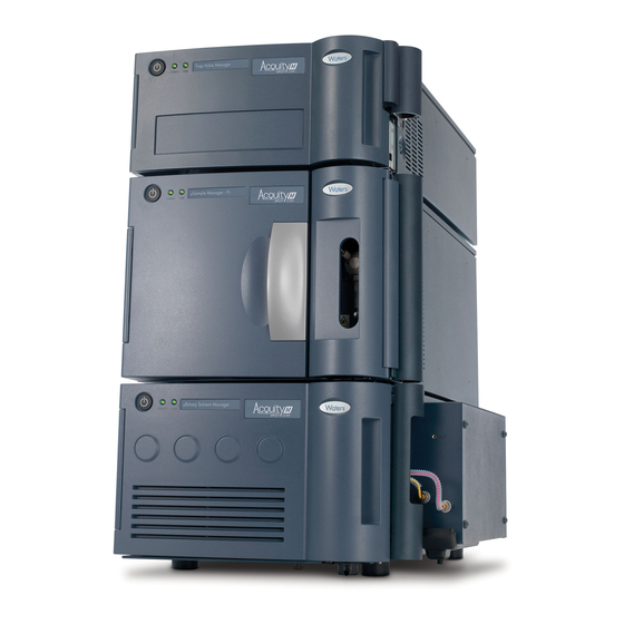
(when used with a tandem mass spectrometer). 1.1 Configurations of system modules This section shows examples of the ACQUITY UPLC M-Class system stack consisting of the core modules. Your system configuration may differ according to the number and types of modules it contains. -
Page 13: Examples Of Typical Acquity M-Class System Configurations
1.1.1 Examples of typical ACQUITY M-Class system configurations Figure 1–1: Single-pump trapping configuration Solvent tray Trap valve manager µSample manager - fixed loop µBinary solvent manager Figure 1–2: Dual-pump trapping configuration Solvent tray Trap valve manager µSample manager - fixed loop November 26, 2019, 715003588 Revision C Page 13... - Page 14 µBinary solvent manager Auxiliary solvent manager Figure 1–3: 2D, 75 µm ID scale configuration Solvent tray µBinary solvent manager Trap valve manager µSample manager - fixed loop µBinary solvent manager November 26, 2019, 715003588 Revision C Page 14...
-
Page 15: System Components
µBinary solvent manager Auxiliary solvent manager Micro cart 1.2 System components The capabilities of the ACQUITY UPLC M-Class system depend on the components installed. The following sections briefly describe the system components and their functions. 1.2.1 System features Review M-Class system features:... -
Page 16: Auxiliary Solvent Manager
• 100-nL, 10-mm path-length, light-guided TUV, and PDA detector flow cells deliver sensitivity and resolution to ACQUITY UPLC M-Class applications on columns ranging from 300-µm to 1.0-mm ID. • The columns, tubings, and fittings support flow rates for a gradient elution from 200nL/min to 100 µL/min at 103,421 kPa (1034 bar, 15,000 psi). -
Page 17: Μsample Manager - Fixed Loop
1.2.4 µSample Manager - Fixed Loop The µSample Manager - Fixed Loop (µSM-FL) manages sample injections. It uses a fixed loop- based mechanism to inject samples. After a puncture needle pierces the covering of a well or vial, a sample needle extends through the puncture needle and aspirates the sample. The aspirated sample is then drawn toward the sample loop while weak-wash solvent is simultaneously dispensed through the needle, behind the sample. -
Page 18: Column Technology
Maintenance Guide 1.2.7.2 Mass detection The ACQUITY UPLC M-Class system maximizes peak capacity, extending the dynamic range of sample analysis. The ACQUITY UPLC M-Class system is frequently used with mass spectrometers, whether analyzing complex samples in wide-ranging matrices with a high- resolution MS, or quantifying peptides, metabolites, or other targeted experiments with tandem MS. -
Page 19: Software
The Waters Driver Pack 2019 Release 2 Installation and Configuration Guide (715006278) on the documentation CD for more information. 1.2.9.1 MassLynx MassLynx software controls the ACQUITY UPLC M-Class system. It acquires, analyzes, manages, and processes mass-spectrometry data. See also: The MassLynx 4.1 Getting Started Guide (71500113203) on the documentation CD for more information about this module. -
Page 20: Additional Information
1.2.10.1 Waters micro cart The optional Waters micro cart provides a mobile platform for the system. The cart holds the system modules and provides electrical outlets. Used with a mass spectrometer, the cart positions the column outlet close to the mass spectrometer’s inlet probe, minimizing system dead volume. - Page 21 • ACQUITY UPLC CSH Columns Care and Use Manual • Controlling Contamination in LC/MS Systems - Best Practices • ACQUITY UPLC M-Class Columns Care and Use Manual • MassLynx 4.1 Getting Started Guide Note: MassLynx software version updates (later than 4.1) are available. Always visit www.waters.com...
-
Page 22: Performance Optimization
Performance optimization Optimal performance of an ACQUITY UPLC M-Class system is achieved when users have a good understanding of the effects of dispersion and carryover, leak-prevention, and sample- preparation techniques. 2.1 Best practices to improve performance Review Waters recommendations for achieving more reproducible chromatography. -
Page 23: Flow Rate On The B Flow Controller
2.1.3 Flow rate on the B flow controller For the most reproducible chromatography, the B side flow controller should operate at flow rates greater than 10 nL/min. To determine the flow rate of the B flow controller, multiply the analytical/trapping flow rate by %B composition in the gradient table. -
Page 24: Re-Equilibration Of Column At The End Of Analysis
2.1.6 Re-equilibration of column at the end of analysis For the most reproducible chromatography, particularly when using flow ramps, the column pressure must return to a stable and consistent value during the system re-equilibration step after the end of the analytical gradient. Recommendation: Investigate the length of the isocratic hold/re-equilibration step during method development phase and optimize if necessary. -
Page 25: General Guidelines For A Microscale System
2.2 General guidelines for a microscale system Separations performed on the ACQUITY UPLC M-Class system use smaller ID columns when compared to an analytical UPLC system. Solvent and sample consumption are significantly reduced. -
Page 26: Dispersion
Waters column packed with sub-2-micron particles provides sufficient back pressure to retard outgassing. If outgassing occurs, Waters recommends using the optional solvent stabilization kit. • Do not submerge the waste or degasser vent lines in liquid. See also: The µBinary Solvent Manager Overview and Maintenance Guide for details on how to route waste and degasser tubing. -
Page 27: Contamination
amount of analyte remains in the system after a sample is injected. You can measure carryover by observing analyte peaks that appear when you run a blank sample immediately after an analytical sample. A common cause of carryover is inadequate washing of the system. Choosing an appropriate wash solvent can minimize carryover for a particular analysis. -
Page 28: Contamination When Operating With Neutral Or Basic Mobile Phases
2.5.1 Contamination when operating with neutral or basic mobile phases Contamination is a concern in neutral and basic pH environments due to the accumulation of bacteria and particulate debris. Notice: To prevent fused silica tubing from dissolving, never use mobile phases exceeding pH 10. -
Page 29: Preventing Leaks
Leaks at high-pressure fittings downstream of the intake valves can leak solvent, but do not introduce air. To prevent leaks, follow Waters recommendations for the proper tightening of system fittings. Note specifically that different techniques apply to retightening fittings versus installing them for the first time. - Page 30 To install capillary tubing: Connect the end nearest the pump source (active end). Click Troubleshoot > Set Pressure Diagnostics. Set the pressure to 70,000 kPa (700 bar, 10,000 psi). Click Start Purge. Flush the tubing for a minimum of two minutes (using 50:50 solvent A/solvent B) to remove any particles.
- Page 31 To assemble the new fittings: Insert the end of a tube into the hexagonal end of the compression screw. Insert the tube into the larger end of the ferrule. Insert the tube into the connection port. Rotate the compression screw, clockwise, into the connection port until the screw is finger- tight.
- Page 32 Note: If ZenFit capillary tubing is used in the system, then you must install the M to ZenFit adapter fitting in each ASM and BSM outlet. Tighten the fitting finger-tight plus an additional 1/2-turn using a 1/4-inch open-end wrench. First-use tightening Reinstalled Flats Compression screw...
- Page 33 2.6.1.3 ZenFit connection technology See also: ionKey Tubing Upgrade Kit with ZenFit Connection Technology for more information. First use or re-installed Knob Screw White safe tightening zone reference area To tighten the fitting: Thread the fitting into the port until the tip contacts the bottom of the port. Tighten the fitting between 30 and 45 degrees (90 degrees max).
- Page 34 was prior to tightening. The second edge of the safe tightening zone is the 90-degree maximum tightening point. Safe tightening zone positions 45° 90° Edge of slot in knob First edge of safe tightening zone Second edge of safe tightening zone 2.6.1.3.1 Testing the port with the port gauge To help ensure leak-free connections, you can test the port's acceptability before installing a ZenFit fitting into a port in a valve, tee, column, or union.
- Page 35 • If the red tip protrudes from the end of the gauge, the port has an imperfection, such as a burr, and is not acceptable for the ZenFit fitting. Note: If the red tip protrudes slightly (less than 1/16 inch, or 1.5 mm, from the end of the gauge), try pushing the spring-loaded tip back into the gauge.
- Page 36 2.6.1.5 1/4-28 flangeless fitting with 2-piece ferrule First use or reinstalled Compression screw Two-piece ferrule Tighten the fitting finger-tight. 2.6.1.6 Long 1/4-28 fitting with flangeless ferrule and stainless steel lock ring installed on 1/8-inch OD tubing First use or reinstalled Compression screw Lock ring Ferrule...
- Page 37 2.6.1.7 Short 1/4-28 fitting with flangeless ferrule and stainless steel lock ring installed on 1/16-inch OD tubing First use or reinstalled Compression screw Lock ring Ferrule End of lock ring with larger inside diameter (ID) Tighten the fitting finger-tight. 2.6.1.8 M-detail fitting (for use with large capillary tubing) First use Short flats Compression screw...
- Page 38 First-use tightening Reinstalled Short flats Compression screw One-piece stainless steel ferrule Tighten the fitting finger-tight plus as much as an additional 1/6-turn using a 3/16-inch open-end wrench. Reinstalled tightening November 26, 2019, 715003588 Revision C Page 38...
- Page 39 2.6.1.9 One piece PEEK fitting Figure 2–6: First use or reinstalled Compression screw Tighten the fitting finger-tight. Tips: • You can also use the column-gripping tool when tightening this fitting. • To prevent band spreading, ensure that the tubing is fully bottomed in the connection port before tightening the fitting.
- Page 40 Figure 2–8: First use tightening Figure 2–9: First use with preset ferrule Flats Compression screw Lock ring Ferrule Tighten the fitting finger-tight until first resistance is felt, plus as much as an additional 1/4-turn using a 1/4-inch open-end wrench. Tip: To prevent band spreading, ensure that the tubing is fully bottomed in the connection port before you tighten the compression screw.
- Page 41 Figure 2–11: Reinstalled Flats Compression screw Lock ring Ferrule Tighten the fitting finger-tight until first resistance is felt, plus as much as an additional 1/4-turn using a 1/4-inch open-end wrench. Figure 2–12: Reinstalled tightening 2.6.1.11 PEEK sample needle fittings The sample needle uses a PEEK compression fitting and two-piece, flat-bottom ferrules. The compression fitting and ferrules differ slightly, depending on the sample needle’s outside diameter.
- Page 42 2.6.1.12 Stainless steel (gold-plated) fitting with long flats and two-piece stainless steel ferrule (V-detail) First use Long flats Compression screw Two-piece stainless steel ferrule Tighten the fitting finger-tight plus an additional 3/4-turn using a 1/4-inch open-end wrench. Tip: To prevent band spreading, ensure that the tubing is fully bottomed in the connection port before you tighten the compression screw.
- Page 43 Tighten the fitting finger-tight plus as much as an additional 1/6-turn using a 1/4-inch open-end wrench. Reinstalled tightening 2.6.1.13 V-detail fitting (for use with small, fused silica capillary tubing) First use Short flats Compression screw Two-piece stainless steel ferrule Tighten the fitting finger-tight plus an additional 3/4-turn using a 1/4-inch open-end wrench. Tip: To prevent band spreading, ensure that the tubing is fully bottomed in the fitting before tightening the compression screw.
- Page 44 Reinstalled Short flats Compression screw Two-piece stainless steel ferrule Tighten the fitting finger-tight plus as much as an additional 1/6-turn using a 1/4-inch open-end wrench. Reinstalled tightening 2.6.1.14 V-detail stainless steel (gold-plated) fitting with long flats and two-piece stainless steel ferrule (for use with stainless steel tubing) First use Long flats Compression screw...
- Page 45 Tip: To prevent band spreading, ensure that the tubing is fully bottomed in the fitting before tightening the compression screw. First-use tightening Reinstalled Long flats Compression screw Two-piece stainless steel ferrule Tighten the fitting finger-tight, plus as much as an additional 1/6-turn using a 1/4-inch open-end wrench.
- Page 46 2.6.1.15 V-detail stainless steel (gold-plated) fitting with short flats and two-piece stainless steel ferrule (for use with stainless steel tubing) First use Short flats Compression screw Two-piece stainless steel ferrule Tighten the fitting finger-tight, plus an additional 3/4-turn using a 1/4-inch open-end wrench. Tip: To prevent band spreading, ensure that the tubing is fully bottomed in the fitting before tightening the compression screw.
-
Page 47: Sample Preparation
Tighten the fitting finger-tight, plus as much as an additional 1/6-turn using a 1/4-inch open-end wrench. Reinstalled tightening 2.7 Sample preparation Micro-scale UPLC analysis places some additional restrictions on sample preparation. Particle-free mobile phase solvents and sample solutions are essential for micro-scale UPLC analysis. -
Page 48: Preparation And Operation
Preparation and operation Preparing the system for use involves starting the system modules, configuring chromatography data-system software, and starting the console software operations. 3.1 Preparing the system Before you can operate the system, you must power-on the system hardware, configure system software, and monitor module status. -
Page 49: Configuring The System Software
For MassLynx installation or upgrade information, see the MassLynx 4.1 Getting Started Guide located on your documentation CD. For software change note (SCN) details, see the associated release notes on the Waters website for the appropriate SCN. Install the ACQUITY UPLC M-Class Driver Pack, update your module firmware, and configure your inlet and system modules. - Page 50 Constant red A module failure prevents further operation. Cycle power to the module. If the LED is still constant red, contact your Waters service representative. Flashing red and green Used as a visual identification of a module after you select it via the console.
-
Page 51: Starting The Instrument Console
Indicates a failure of a module that prevents its further operation. Power-off the module, and then restart it. If the LED is still steady red, contact your Waters service representative. Flashing red and green Used as a visual identification of a module after it is selected via the console. -
Page 52: Instrument Control Panels
From the instrument console's interface, you can quickly navigate to visual representations of each module and its components. You can also navigate to interactive diagrams, which show interconnections and provide diagnostic tools for troubleshooting problems. To start the instrument console from MassLynx software: In the MassLynx window, click Inlet Method. - Page 53 Stop flow The Stop Flow control immediately stops all flow from the solvent manager. Flow rate Displays the total flow rate of the solvent manager. • µBSM from 0.000 to 100 µL/min under normal operation, and 0.000 to 8.000 mL/min when priming. •...
-
Page 54: Μsm-Fl Control Panel
Warning indicator Displays the warning indicator icon when the liters pumped is exceeded. You can access additional functions, shown in the following table, by right-clicking anywhere in the solvent manager’s control panel. Table 3–5: Additional functions in the solvent manager control panel Control panel function Description Prime A/B solvents... - Page 55 Run LED Depicts the actual run LED on the front panel, unless communications to the µSM-FL are interrupted. Warning indicator Displays the warning indicator icon when number of injections threshold (set by the user) is exceeded. Display console Launches the instrument console. Column-temperature Displays the current column-temperature set point to 0.1 °C set point...
-
Page 56: Tvm Control Panel
3.3.3 TVM control panel Figure 3–4: TVM control panel Run LED Depicts the actual run LED, on the front panel, unless communications to the TVM are interrupted. Warning indicator Displays warning indicator icon when you exceed valve cycle counters. Left valve position Displays the current position (position 1 or position 2). -
Page 57: Maintaining The System
4.1 Contacting Waters Technical Service If you are located in the USA or Canada, report malfunctions or other problems to Waters Technical Service (800-252-4752). From elsewhere, phone the Waters corporate headquarters in Milford, Massachusetts (USA) or contact your local Waters subsidiary. The Waters website includes phone numbers and email addresses for Waters locations worldwide. -
Page 58: Maintenance Procedure And Frequency
Be prepared to provide the serial numbers of the modules that comprise the system when you report a problem to Waters Technical Support. To locate system serial numbers: In the console, select a module from the system tree. - Page 59 Table 4–1: ACQUITY UPLC M-Class system maintenance procedures Maintenance procedure Frequency Perform leak test As needed. For instructions on evaluating the fluid-handling integrity of the system, see the online Help regarding the following diagnostic tests: • Fluid integrity test • Dynamic leak test •...
- Page 60 Table 4–2: Solvent manager maintenance procedures (continued) Maintenance procedure Frequency Replace the i Valve cartridge As part of the annual scheduled routine maintenance and thereafter, as needed. The typical failure modes are as follows: • Retention times are later than expected when a dynamic leak test is performed, resulting in a leak rate above the acceptable limit.
- Page 61 Table 4–2: Solvent manager maintenance procedures (continued) Maintenance procedure Frequency Replace the in-line filter As needed. The typical failure modes are as follows: • High back pressure: the in-line filter causes a high-pressure shutdown. In this case, disconnect the in-line filter. If the system exhibits pressure decay, determine the system pressure at known conditions.
- Page 62 Table 4–2: Solvent manager maintenance procedures (continued) Maintenance procedure Frequency Replace the plunger and seals As part of the annual scheduled routine maintenance and thereafter, as needed. The typical failure modes are as follows: • Late eluting peaks are exhibited after a dynamic leak test is performed where the leak rate is above the acceptable limit.
-
Page 63: Troubleshooting
4.3 Troubleshooting When a malfunction occurs, you must systematically troubleshoot the system to isolate the problem. 4.3.1 General principles Follow these general principles for troubleshooting the ACQUITY UPLC M-Class system: November 26, 2019, 715003588 Revision C Page 63... -
Page 64: Troubleshooting M-Class System Devices
• Consider the likely causes of the problem. For example, unresponsive modules can mean that power or signal cables are disconnected or improperly connected. A fluid or vacuum leak can indicate defective tubing or valve connections. • Look for the less obvious causes of a problem: •... - Page 65 Suspected cause Possible solution Loose fittings or crimped lines before or after Inspect all fittings and tubing. Replace as the column necessary. Inadequate solvent blending If the baseline is steady when running a premixed solvent, then: • Ensure that A and B pumps are delivering solvent correctly.
- Page 66 (for a minimum of 30 minutes). If the problem persists: • Run the column heater temperature at 5 °C above ambient. • Close any open air vents. • Contact your Waters service representative. November 26, 2019, 715003588 Revision C Page 66...
- Page 67 Suspected cause Possible solution Inconsistent retention times • Flush the column with 85% organic solvent. • Clean or replace the column as described in the appropriate column care and use manual on the documentation CD. • Rerun the analysis and observe whether the retention times stabilize.
- Page 68 Suspected cause Possible solution Inlet lines blocked • Inspect lines for blockages and replace tubing if necessary. • Clean the solvent inlet filter frit and replace the frit if necessary. See also: Mobile phase contaminated Controlling Contamination in Ultra Performance LC/MS and HPLC/MS Systems on the documentation CD.
- Page 69 4.3.2.6 Late eluting peaks fail Suspected cause Possible solution Inappropriate gradient method Use the correct gradient method. Incorrect trapping conditions Use the standard trapping conditions. Incorrect sample preparation Prepare the sample correctly. 4.3.2.7 Missing peaks Suspected cause Possible solution Detector problems •...
- Page 70 4.3.2.9 Fronting peaks Suspected cause Possible solution Injection volume or sample concentration is too Reduce the injection volume or dilute the high, disrupting column equilibrium. sample. Sample diluent is too high in organic for the Reduce the injection volume or reduce the initial mobile phase.
- Page 71 Suspected cause Possible solution Incorrect diluent makeup Confirm the diluent used for preparing the sample. Column conditioning or re-equilibration Ensure that the column is adequately problem conditioned or equilibrated. Insufficient trapping • Confirm the inlet method parameters. • Confirm that the trapping column is trapping peptides efficiently.
- Page 72 Suspected cause Possible solution Needle weak wash solvent is too high in Ensure that the weak needle wash solution is organic. similar to the initial mobile phase. In-line filter, column inlet, or connecting tubing Inspect these components for particle build-up. is partially blocked.
- Page 73 Suspected cause Possible solution Void volume or bad consumables Perform a systematic replacement of consumables beginning with the analytical column. 4.3.2.15 Loss of sensitivity Suspected cause Possible solution Wrong injection volume; less sample loaded on Change to correct injection volume. a column results in a lower response.
-
Page 74: Configuring Maintenance Warnings
You can specify usage thresholds and maintenance warnings that alert you when a component reaches a specified threshold. You can minimize unexpected failures and unscheduled downtime during important work. For information explaining how to specify maintenance warnings, consult the Waters console Help. November 26, 2019, 715003588 Revision C Page 74... -
Page 75: Spare Parts
Waters Quality Parts. Visit www.waters.com/wqp for information about Waters Quality Parts, including how to order them. For information about compatible plates, vials, caps, and sample covers, consult the Waters Vials, Filters, and Plates selector: https://www.waters.com/app/selector/en/index.html. November 26, 2019, 715003588 Revision C Page 75... -
Page 76: A Safety Advisories
Heed all warnings when you install, repair, or operate any Waters instrument or device. Waters accepts no liability in cases of injury or property damage resulting from the failure of individuals to comply with any safety precaution when installing, repairing, or operating any of its instruments or devices. -
Page 77: Notices
Warning: (Risk of injury caused by moving machinery.) Warning: (Risk of exposure to ultraviolet radiation.) Warning: (Risk of contacting corrosive substances.) Warning: (Risk of exposure to a toxic substance.) Warning: (Risk of personal exposure to laser radiation.) Warning: (Risk of exposure to biological agents that can pose a serious health threat.) Warning: (Risk of tipping.) Warning:... -
Page 78: Required Protection
A.6 Biohazard warning The following warning applies to Waters instruments and devices that can process biologically hazardous materials. Biologically hazardous materials are substances that contain biological agents capable of producing harmful effects in humans. -
Page 79: Warnings That Apply To All Waters Instruments And Devices
Consult the Safety Data Sheets regarding the solvents you use. Additionally, consult the safety representative for your organization regarding its protocols for handling such materials. A.7 Warnings that apply to all Waters instruments and devices When operating this device, follow standard quality-control procedures and the equipment guidelines in this section. - Page 80 Warning: Use caution when working with any polymer tubing under pressure: • Always wear eye protection when near pressurized polymer tubing. • Extinguish all nearby flames. • Do not use tubing that has been severely stressed or kinked. • Do not use nonmetallic tubing with tetrahydrofuran (THF) or concentrated nitric or sulfuric acids.
- Page 81 Avvertenza: fare attenzione quando si utilizzano tubi in materiale polimerico sotto pressione: • Indossare sempre occhiali da lavoro protettivi nei pressi di tubi di polimero pressurizzati. • Spegnere tutte le fiamme vive nell'ambiente circostante. • Non utilizzare tubi eccessivamente logorati o piegati. •...
- Page 82 • 非金属チューブには、テトラヒドロフラン(THF)や高濃度の硝酸または硫酸などを流さないでくださ い。 • 塩化メチレンやジメチルスルホキシドは、非金属チューブの膨張を引き起こす場合があり、その場 合、チューブは極めて低い圧力で破裂します。 This warning applies to Waters instruments fitted with nonmetallic tubing or operated with flammable solvents. Warning: The user shall be made aware that if the equipment is used in a manner not specified by the manufacturer, the protection provided by the equipment may be impaired.
-
Page 83: Warnings That Address The Replacement Of Fuses
警告: 使用者必須非常清楚如果設備不是按照製造廠商指定的方式使用,那麼該設備所 提供的保護將被消弱。 경고: 제조업체가 명시하지 않은 방식으로 장비를 사용할 경우 장비가 제공하는 보호 수단이 제대로 작동하지 않을 수 있다는 점을 사용자에게 반드시 인식시켜야 합니다. 警告: ユーザーは、製造元により指定されていない方法で機器を使用すると、機器が提供している 保証が無効になる可能性があることに注意して下さい。 A.8 Warnings that address the replacement of fuses The following warnings pertain to instruments and devices equipped with user-replaceable fuses. Information describing fuse types and ratings sometimes, but not always, appears on the instrument or device. -
Page 84: Electrical Symbols
警告: 火災予防のために、ヒューズ交換では機器ヒューズカバー脇のパネルに記載されているタイプお よび定格のヒューズをご使用ください。 Finding fuse types and ratings when that information does not appear on the instrument or device: Warning: To protect against fire, replace fuses with those of the type and rating indicated in the “Replacing fuses” section of the Maintenance Procedures chapter. Avertissement : pour éviter tout risque d'incendie, remplacez toujours les fusibles par d'autres du type et de la puissance indiqués dans la rubrique "Remplacement des... -
Page 85: Handling Symbols
Symbol Description Electrical power off Standby Direct current Alternating current Alternating current (three phase) Safety ground Frame or chassis terminal connection Fuse Functional ground Input Output Indicates that the device or assembly is susceptible to damage from electrostatic discharge (ESD) A.10 Handling symbols The following handling symbols and their associated statements can appear on labels affixed to the packaging in which instruments, devices, and component parts are shipped. - Page 86 Symbol Description Fragile! Use no hooks! Upper limit of temperature Lower limit of temperature Temperature limitation November 26, 2019, 715003588 Revision C Page 86...
-
Page 87: B Specifications
Specifications The specifications presented in this document depend on the conditions that exist in individual laboratories. Refer to the site preparation guide or contact Waters Technical Service for additional information about specifications. B.1 Features and performance specifications The following tables list the performance specifications for the ACQUITY UPLC M-Class system and system components. - Page 88 Table B–2: ASM performance specifications Feature Specification Column trapping pump (A side) Choice of two eluents NanoLockSpray addition (B side) Choice of two lockmass solutions Flow rate range A side: 0.0 mL/min to 1.0 mL/min B side: 0.0 µL/min to 100.0 µL/min Solvent conditioning Integrated vacuum degassing, six lines Primary check valves...
- Page 89 ±1.0 °C at sensor Injection needle wash Integrated, active, programmable, dual wash Minimum sample required 3 µL residual, using Waters total recovery vials (zero offset) Advanced sample manager capabilities Load Ahead and Loop Offline mode, valve cycling timed event, multi-load with trapping...
- Page 90 Table B–5: Sample organizer performance specifications Feature Specification Sample plate capacity Sample plate capacity is configured based on the types and combinations of plates being used: • Maximum of 19 standard microtiter plates, up to 15.5 mm high • Maximum of nine intermediate height plates (or 2-mL vial holders), up to 40.0 mm high •...
-
Page 91: Instrument Control
The following table lists the electrical specifications for the ACQUITY UPLC M-Class system. Note: The total ACQUITY UPLC M-Class system power is a function of the modules and instruments that comprise it. Refer to the module or instrument operator’s guide for further information. -
Page 92: Physical Specifications
SO: 540 VA TVM: 150 VA B.5 Physical specifications The following table lists the physical specifications for the individual ACQUITY UPLC M-Class system components. Notes: • Provide clearance of at least 15.2 cm (6 inches) on the back side of each component for ventilation. - Page 93 Table B–10: System components physical specifications (continued) System Depth Height Width Weight component TUV detector 60.9 cm 19.3 cm 34.3 cm 12.0 kg (24.0 inches) (7.6 inches) (13.5 inches) (26.5 pounds) See also: If your system includes a mass spectrometer, refer to the relevant operator’s overview and maintenance guide for physical specifications.
-
Page 94: C External Connections
Requirements: • Contact Waters Technical Service before moving the system modules. • If you must transport a system component, or remove it from service, contact Waters Technical Service for recommended cleaning, flushing, and packaging procedures. Notice: To avoid spinal and muscular injury, do not attempt to lift a system module without assistance. -
Page 95: External Wiring Connections
Solvent tray µSM-FL µBSM Process waste container Micro cart C.2 External wiring connections Figure C–2: Example of process waste management Ethernet switch µSM-FL November 26, 2019, 715003588 Revision C Page 95... -
Page 96: Ethernet Connections
µBSM Power connectors Ethernet connectors C.2.1 Ethernet connections The µSM-FL incorporates an internal 10/100/1000 megabit Ethernet switch that accommodates the PC (workstation) and up to six system modules. Connect the shielded Ethernet cables from each module to the electronic connections on the rear panel of the µSM-FL. C.3 Signal connections C.3.1 Connecting signal cables Refer to the signal connection location shown on the silk-screened label affixed to the rear panel... - Page 97 Figure C–3: Inserting the connector into the connector port Connector port Connector Using the flat-blade screwdriver, attach the positive and negative leads of the signal cable to the connector. Tip: Refer to the cable-connection label affixed to the rear panel of the module. Figure C–4: Positive and negative lead connections Screw Connector...
-
Page 98: Connecting To The Electricity Source
To avoid electric shock, observe these precautions: • Use SVT-type power cords in the United States and HAR-type power cords, or better, in Europe. For requirements elsewhere, contact your local Waters distributor. • Inspect the power cords for damage and replace them if necessary. -
Page 99: Connecting To A Cart's Electricity Source
Recommendation: Use a line conditioner and uninterruptible power supply (UPS) for optimum, long-term, input-voltage stability. Contact Waters to ensure the correct selection and size. To connect to a wall electricity source: Connect the female end of the power cord to the receptacle on the rear panel of the module. - Page 100 C.4.2.1 Micro cart power connections Figure C–6: Micro cart power connections Note: The connection between the connector and the Ethernet switch, detector, µSM-FL, and µBSM is one meter each. The connection between the connector and the ASM is two meters. A universal IEC coupler runs between the connector and detector.
- Page 101 To circuit B Micro cart power strips To circuit A AC line November 26, 2019, 715003588 Revision C Page 101...
-
Page 102: D Solvent Considerations
Solvent considerations This information applies to the ACQUITY UPLC M-Class System modules. Warning: Observe Good Laboratory Practice (GLP) at all times, particularly when working with hazardous materials. Consult the Safety Data Sheets regarding the solvents you use. Additionally, consult the safety representative for your organization regarding its protocols for handling such materials. -
Page 103: Pure Water Is Required
This section lists solvents recommended for the ACQUITY UPLC M-Class System. Contact Waters Customer Service to determine whether you can use solvents that do not appear in the list without adversely affecting performance of system modules or the system itself. -
Page 104: Solvents To Avoid
Recommendation: To avoid damaging capillary tubes, never use mobile phases exceeding pH Note: Adding organic solvent reduces contamination. Waters recommends that you pre-filter the mobile phase. • Use clean water and glassware. • Add up to 20% of an organic solvent; use acetonitrile or methanol when possible. - Page 105 • Replace bottle sinkers at least monthly. • Condition following neutral or basic mobile phase operation. D.2.4.1 Using clean water and glassware Using clean water and glassware is essential to keeping microbial levels sufficiently low. Use MS-grade water filtered to 0.1 μm or smaller. If you use water from an ultra purification system, follow all the manufacturer's guidelines regarding use, maintenance, service, cleaning, and parts replacement.
- Page 106 • Vacuum filtration kit; for example, WAT085113, which includes a filter holder, flask, vacuum pump, and filters • Additional Membrane filters, 0.1 μm or smaller, PVDF To filter neutral or basic mobile phase: Rinse all wetted surfaces of the vacuum filtration system with MS-grade isopropanol and allow the surfaces to dry.
- Page 107 D.2.4.5 Cleaning the system Cleaning the system kills and removes any residual bacteria present in the system. Clean the system before performing an operation using neutral or basic mobile phase (or if you encounter problems associated with neutral or basic mobile phase operation). Requirement: You must clean the entire fluidic path that is exposed to high pH solvent.
- Page 108 Prime the seal wash line with 70% isopropyl alcohol for 10 minutes or more. Place lines A1, A2, B1, and B2 in the solution. Tip: If you will not use A2 and B2 lines for high pH solvent, you can place only A1 and B1 in the solution, skip step 9 and step 12, and use A1 and B1 for step 10.
- Page 109 Note: See the high-pH fluidic path (in blue) in the following figure. Before flushing, insert the iKey Infusion device. Figure D–3: ionKey/MS direct injection system configuration November 26, 2019, 715003588 Revision C Page 109...
- Page 110 Figure D–4: Host cell protein analysis (HCP) system configuration Note: See the high-pH fluidic path (in blue) in the following figure and note that dilution occurs at the tee. Before flushing, substitute a union for the 1.0-mm column and set the TVM right valve to position 1.
- Page 111 2. Before flushing, substitute a union for the 300-µm ID column and set the TVM right valve to position 1. D.2.4.5.3 Cleaning the sample manager Restriction: Use this procedure on ACQUITY UPLC M-Class systems only. It is not compatible with other ACQUITY UPLC systems. Required materials • 70% LC/MS-grade isopropanol 30% water solution To clean the sample manager: Verify that the sample manager injection valve is in the Load position.
- Page 112 In the Injection Valve dialog box, click Load. Click Control to end the editing session. Insert the strong and weak wash lines in a bottle of 70% LC/MS-grade isopropanol 30% water solution. Prime the sample manager for at least six cycles, as follows: In the console system tree, select the sample manager.
-
Page 113: System Recommendations
• Consider using chloroform, methylene chloride, halogenated solvents, or toluene in weak dilutions (less than 10% volume) as additives, modifiers, or sample diluents. • Waters does not recommend methanesulfonic acid for use in ACQUITY UPLC M-Class systems. • Always use properly cleaned and maintained glassware. -
Page 114: Μsm-Fl Recommendations
D.3.2 µSM-FL recommendations • Typical organic sample diluents such as dimethylsulfoxide (DMSO) and dimethylformamide (DMF) are supported. • Do not use buffers as needle wash solvents. You can use acids and bases. D.4 Properties of common solvents The following table lists the properties for some common chromatographic solvents. Table D–1: Properties of common solvents Solvent Vapor pressure mm... -
Page 115: Solvent Miscibility Effects
Table D–1: Properties of common solvents (continued) Solvent Vapor pressure mm Boiling point (°C) Flash point (°C) Hg (Torr) Methanol 97 at 20 °C 64.7 Methyl t-butyl ether 240 at 20 °C 55.2 Methyl ethyl ketone 74 at 20 °C 79.64 Methyl isobutyl ketone 16 at 20 °C 117.4... -
Page 116: Using Miscibility Numbers (M-Numbers)
Table D–2: Solvent miscibility Polarity Solvent Viscosity cP, Boiling Miscibility λ cutoff (nm) index 20 °C point °C number (M) (@1atm) (@1atm) N-hexane 0.313 68.7 — Triethylamine 0.38 89.5 — 1-propanol 2.30 97.2 2-propanol 2.35 117.7 — Ethanol 1.20 78.3 Benzyl 5.80 205.5... -
Page 117: Solvent Viscosity
• The first number, always lower than 16, indicates the degree of miscibility with highly lipophilic solvents. • The second number applies to the opposite end of the scale. A large difference between these two numbers indicates a limited range of miscibility. For example, some fluorocarbons are immiscible with all the standard solvents and have M- numbers of 0 and 32.
Need help?
Do you have a question about the ACQUITY UPLC M-Class and is the answer not in the manual?
Questions and answers