
Related Manuals for Microtest 8740

Summary of Contents for Microtest 8740
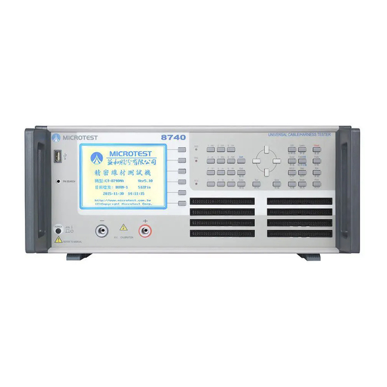
- Page 1 8740 2-Wire Universal Cable/Harness Tester User Manual Version: 1.12 Publish date: October 2019...
-
Page 2: Table Of Contents
Table of Content Chapter 1. Precautions ........................... 3 Safety Signs ..........................3 Do not modify or make internal adjustments to this machine ........... 3 Static Electricity ......................... 3 Ground ............................3 Power ............................3 Warm Up ............................ 3 Machine Malfunction ......................... 4 Test End ............................. - Page 3 APPENDIX B Test Range and Functions ....................74 APPENDIX C Technical specifications ....................75 APPENDIX D Version ..........................76 Microtest Corporation all rights reserved. Declaration: Microtest Corporation reserves the right to modify the contents of this manual without further notice!
-
Page 4: Chapter 1. Precautions
Chapter 1. Precautions This instrument is not suitable for outdoor use, especially in humid or highly dusty locations. Improper use of this instrument may result in electric shocks. Please read the safety descriptions carefully before using this tester in order to avoid improper or wrong use causing accidents. Safety Signs The following safety signs may appear in this manual and on this instrument. -
Page 5: Machine Malfunction
Machine Malfunction When the instrument malfunctions, please send the machine back to the original manufacturer to have professionals repair it for you in order to ensure the accuracy and operation safety of the meter. Test End Please switch the machine power off when the machine is not used for an extended amount of time. Placement and Storage The operating temperature and humidity range of this machine is 18 C - 28... -
Page 6: Chapter 2. General Description
Chapter 2. General description Package and Accessories Standard accessories included in the 8740 series cable tester package should include the following items: 1 x 8740 cable tester 2 x moving needle type boxed connector 1 x automatic pin search probe ... -
Page 7: Basic Operations Of The Tester
Basic Operations of the Tester Alphanumeric input Alphanumeric characters need to be inputted when saving files; the design used for this system is EditKey. The first time it is pressed it will be the number; the time will be the capital English letter from the left to the right on top of the number buttons respectively;... -
Page 8: Front And Rear Panel Functions
Front and Rear Panel Functions 2.4.1 Front Panel 128 and 256 models ○ LCD display S1-S6 operation auxiliary buttons (Soft Key) PASS & FAIL & HIPOT LED Control button (Edit Key) group Test shortcut button group System reset (Reset) button Power switch Pin search connector 128Pin has 2 slots and 256 Pin has 4 slots... - Page 9 512 model LCD display S1-S6 operation auxiliary buttons (Soft Key) PASS & FAIL & HIPOT LED Control button (Edit Key) group Test shortcut button group System reset (Reset) button Power switch Pin search connector, 512Pin has 8 slots 512Pin has 8 slots Test button [TEST] (10) System button (Sys Key) group...
-
Page 10: Rear Panel
2.4.2 Rear panel 128 Model: (1) Serial port (RS-232 Port) (2) Remote control port (Remote Port) (3) Printer Port (4) High voltage correction output connector (5) AC power input (230/115 VAC) (6) 115/230V switch Fuse Holder 250V/T1.25A. (8) Audio output socket Note: 1. - Page 11 512 model: (1) Serial port (RS-232 Port) (2) Remote control port (Remote Port) (3) Printer Port (4) AC power input (230/115 VAC) (5) 115/230V switch (6) Fuse holder 250V/T1.25A. (7) Audio output socket Note: 1. Please confirm whether the AC input voltage setting is the same as the voltage used.
-
Page 12: Function Block Diagram
Function Block Diagram [Mode] [TEST] Test mode setting Comprehe nsive test [Func] Mode Function setting Conduction Test setting Yes/No [Setup] Mode System Settings DC insulation Test setting AC tolerance Yes/No setting [Stat] Statistical data R setting Test Yes/No [Print] Print setting C setting Test Yes/No... -
Page 13: Installation
(2) Connect the connector and test cable according to usage needs. (3) Turn on the power; the system will execute the self-test program. (4) When the execution of the self-test is completed, it will officially enter the 8740 system; the LCD display will be as follows: (5) To end the system, please press the [Power switch] to end. - Page 14 Makes the backlight of the LCD brighter Makes the backlight of the LCD darker Increases the volume level Decreases the volume level Software version and update date display Switch between Chinese/English Quickly switches to the short circuit table function (same as [O/S]) Quickly switches to the learning function (same as [Learn]) Quickly switches to file manager (same as [File]) Quickly switches to conductance edit function (same as [Cond])
-
Page 15: Button Instructions
Button Instructions 【1】 System (Sys Key) button group [Func] System function menu [Sys] System setting menu [Print] Print function menu 【2】 Test shortcut (Fast Key) button group [File] File manager setting [Learn] Short circuit learning [Stat] Display test statistics data [Mode] Test mode setting [O/S]... - Page 16 【4】 [Enter] Confirm button 【5】 [TEST] Start test button 【6】 Operation Auxiliary Button (Soft Key) Group S1-S6 are located to the right of the LCD; they are used for auxiliary operations/settings. 【7】 [Reset] System reset button, which works the same as warm start 【8】...
-
Page 17: Chapter 3. Function Setting And System Setting
Function setting and System setting Chapter 3. The function settings and analysis modes include main system functions [Func], system settings [Setup] and print function [Print]; descriptions are as follows: Function Provides the main function for the system; its operations and function descriptions are as follows: (1) Press [Func]. -
Page 18: Self-Test
3.1.2 System Info. This item allows for the viewing of the 8740 machine and version information; it lists the machine’s model number, test pins, total space used by files, and the total remaining space, etc. And it can perform system update. -
Page 19: Calibration
3.1.3 Calibration This function includes [1] DC H.V.CAL, [2] AC H.V. CAL [3] AC H.V. CAL [4] Curr.Fix.CAL. (1) Press [Func]. (2) Please use [↑] or [↓] to select Calibration and then press [Enter]. (3) The LCD screen will display as follows: (4) Press [Exit] to exit. - Page 20 AC H.V. CAL The AC high voltage correction is used to adjust the READING (test value) closest to the AC setting value. (1) Press [Func]. (2) Please use [↑] or [↓] to select Calibration and then select AC H.V. CAL. and press [Enter]. (3) The LCD screen will display as follows: (4) Press S1 [UP] or S2 [DOWN] to adjust the READING (test value) closest to the DC setting value.
- Page 21 INT.COND.ZERO This function can execute the internal resistance offset action of the machine. (1) Press [Func]. (2) Please use [↑] or [↓] to select Calibration and then select INT.COND.ZERO and press [Enter]. (3) The LCD screen will display as follows: (4) Press [Enter] to execute the internal resistance offset action (when you want to execute internal resistance offset, please first insert the INTERNAL OFFSET board).
- Page 22 Constant Current Box Calibration: This function is an optionally purchased fixture calibration option. Press [Func]. Please use [↑] or [↓] to select measurement parameter calibration, and then select constant current box calibration Curr.Fix.CAL and press [Enter]. The LCD screen will display as follows:...
-
Page 23: Pin Search
3.1.4 Pin Search This function can display which is the current output pin. (1) Press [Func]. (2) Please use [↑] or [↓] to select pin search and then press [Enter]. (3) Connect the probe to the pin search connection, and point the probe to the pin you want to find out. (4) The LCD screen will display as follows: (5) A36 and B29 in the figure represents the 36th pin of slot A and the 29th pin of slot B respectively. -
Page 24: Ethernet Fixture Setting (Ethernet Fix.)
3.1.5 Ethernet Fixture Setting (Ethernet Fix.) This function sets the protocol, IP, and server port, etc. for networking. Press [Func]. (2) Please use [↑] or [↓] to select find network fixture setting (Ethernet Fix.) and press [Enter]. (3) The LCD screen will display as follows: [1] Protocol: TCPC: Transmission Control Protocol Client TCPS: Transmission Control Protocol Server... -
Page 25: System Setup (Sys)
System Setup (SYS) System setting includes system configuration and test related action settings; their operation and function descriptions are as follows: (1) Press [Sys]. The LCD screen will display as follows: (3) Please use [↑] or [↓] to select the item needed and then press [Enter]. (4) Press [Exit] to exit when completed. - Page 26 Power ON Self-Test There is a total of two options: The default value is │On│. On: Perform power on self-test. Off: Do not perform power on self-test. (2) Power Line Freq Set the input power frequency (50Hz/60Hz). (3) Key Stroke Sound This tester allows enabling/disabling button sounds according to the needs.
- Page 27 (7) Inverse LCD Press S1 or →← [Item selection] to switch the LCD display method. (8) Language Press S1 or →← [Item selection] to switch between Chinese or English display. (9) Baud Rate Press S1 or →← [Item Selection] to switch between1200, 2400, 4800, 9600, 14400, 19200, 38400, 57600, and 115200.
-
Page 28: Setting The Test Environment
3.2.2 Setting the Test Environment (1) The LCD screen will display as follows:... - Page 29 (2) Please use [↑] or [↓] to select the item needed. (3) If needed, please press S1 (PROG) or ←→ [Item selection] to switch. (4) Press [Exit] to exit when completed. (1) TESTER ID Allows assigning an ID for this tester. (2) TEST ALARM This function provides alarms for test results;...
- Page 30 STATIC: Remote control is continuous output until the next test. When you are unsure of the PLC reception speed, please set it as continuous mode, and note that the output signals all have a pull-up resistor of 4.7K when sent to PLC input. PULSE: When the remote control has a pulse output of 200ms.
- Page 31 (15) Mul.DUT OPT 4: The maximum number of DUTs that can be set for MultiDUT is 4 sets. 14: The maximum number of DUTs that can be set for MultiDUT is 14 sets (expansion box required for use with REMOTE signal output). (16) SF.Stat MODE General: Statistics is performed once the test has completed.
- Page 32 (27) COND AVG TIMES Conduction test times 1-99. (28) SEQ. STAT General: Statistics is performed once the test has completed. MultiDUT MUL.DU: When the test has completed, multiple DUTs will be included in the statistics. (29) AF.TSET TIME Total test time for fixture current box; the test results within this time are aggregated and averaged.
-
Page 33: Setting The System Time
3.2.3 Setting the System Time This function can adjust the system’s year/month/day/hour/minute/second. (1) Press [Sys]. (2) Use [↑] or [↓] to select [3]Date/Time function. (3) The LCD screen will display as follows. (4) The time format is MM/DD/YY; please press S1 [SET] to save when input is completed. (5) Press [Exit] to exit. -
Page 34: Changing The System Password
3.2.4 Changing the System Password This tester provides key lock protection in order to prevent data from being modified randomly. (1) Press [Sys]. (2) Please use [↑] or [↓] to select this item and then press [Enter]. (3) The LCD screen will display as follows. (4) If you are setting the password for the first time, enter the new password directly. -
Page 35: Print
Print This tester provides direct printer output, making it easy for you to print out the data needed; its operation and function descriptions are as follows: (1) Select the data or screen needed. (2) Simply press [Print]. Learn The short circuit setting of this machine is set by learning, which means saving the test cable connection conditions in the system memory and the system will display the test results on the LCD. -
Page 36: Statistic
Statistic This function allows viewing of the test result statistical data, including: total number of tests, number of passes, number of fails and cause of failure analysis, which searches for the number of fails in each item category. (1) Press [Stat]. (2) The LCD screen will display as follows. -
Page 37: Mode
Mode Press [O/S] and then press S6 [O/S EDIT] to enter TEST MODE. (1) PressS6(NEXT PAGE) (2) The LCD will display the following screen:... - Page 38 [1] O/S Threshold: Available options include 2K, 5K, 10K, 20K and 100K; other functions are used to determine the short circuit value. If it is set as 2K, cables with resistance under 2K are considered to be short-circuited and with resistance above 2K are considered to be open circuit. [2] Max.
- Page 39 (1) Press [Mode] (2) The LCD screen will display as follows: CABLE TYPE: {NORMAL} Press [Learn]; the LCD screen will display as follows: When performing the cable test, press [TEST] and the LCD screen will display as follows: From the LCD display screen, we can find out the total number of tests and the number of passes and fails.
- Page 40 (1) When test mode is being set, set the cable type as {SINGLE STEP}. Press [Learn]; the LCD screen will display as follows: Use the automatic pin search probe to specify the short circuit pin to test; example is as follows: When using the PIN SEARCH probe on the panel, touch the relative position (A01) specified by the cable and the LCD will display that pin.
- Page 41 Please use the automatic pin search probe and place it on A01; the LCD screen will display as follows: The automatic pin probe must be placed on A03, A05, and A07 sequentially in order to complete the cable test action.
- Page 42 Since we initially have 4 steps preset, so for the test of each DUT, steps 1 to 4 of the step test must be completed successfully in order for it to pass. A maximum of 128 test steps can be set. When test mode is being set, set the cable type as {unilateral}.
- Page 43 When performing the cable test, press [TEST] and the LCD screen will display as follows: From the LCD display screen, we can find out the total number of tests and the number of passes and fails.
- Page 44 [2] START UP MODE: AUTO SCAN Starts test after the DUT is inserted. MANUAL Press the Test button after the DUT is placed to start the test. CONTINUE Continuous tests are performed after the Test button is pressed. [3] AUTO SCAN DELAY: This is only effective when Automatic is selected as the test start method;...
-
Page 45: Multdut
3.7.1 MultDut First learn the DUT pin; press mode setting. Select MULTIDUT The selection is, set the start and end of the DUT according to the pin learned; a maximum of 4 tests can be selected and the start and end pins of the DUT can be set. (P.S There must be no other DUT at the start and end of the DUT.) Press “TEST”... -
Page 46: Item
3.7.2 Item Press Mode. Press Test Mode. (1) Please use [↑] or [↓] to move to the item you want to set. (2) Press S1 [Item selection] to switch whether to execute test for the selected item. -
Page 47: Chapter 4. Comprehensive Test Mode
Comprehensive Test mode Chapter 4. Test mode uses programmed design functions to perform simultaneous and automatic tests according to the different test conditions set for different test items in order to satisfy different needs and achieve optimal efficiency; it can be divided into: ●... -
Page 48: Conductance
4.1.2 Conductance (1) Press [Cond]. (2) The LCD screen will display as follows. (3) Please use [↑] or [↓] to select the item you want to set. Maximum conductance value: Please use the number buttons to enter a value according to your needs as the upper limit of the cable conductance. - Page 49 Press S1 [Select] the item needed and then press S4 [Import component]: Import to component edit: Cable off: After inserting the offset fixture, press S5 [COMD ZERO] to perform offset, and the cable offset located at the bottom left will display: Yes. Clear offset: Press S6 [CLR ZERO] to clear the previous conduction value, and the cable offset located at the bottom left will display: None.
-
Page 50: R/C/D Component Setting Edit (Resistance)
(open all four channels) Point When the 8740 host is used with the 8740 CC3 constant current box to perform cable voltage drop test, use of a genuine fixture adapter board is recommended; if users need to use their own adapter board, please beware of the PIN definitions of the DUT and the PIN definitions in the previous table, as well as the operation restrictions. - Page 51 results; users must beware of the difference of this setting. (5) Set the + - pins; the pins can be entered manually or use automatic pin search (to use automatic pin search, the probe must be inserted to the PIN SEARCH located at the front panel and then touch the ABCDEFG Port pins);...
- Page 52 (8) Press [Enter] to perform the offset action. (9) Press S6 [ALL SAME] to clear the data used for resistance or capacitance offset. (10) When the component is resistance, press SHIFT+S5 [CLR.OFFS] to display the data for resistance offset; the LCD screen will display as follows: (11) When the component is diode or current leakage, press S3 [SET PARA] to perform parameter setting;...
- Page 53 Pin (Positive pin) Positive pin setting; please enter the pin selected. Pin (negative pin) Negative pin setting; please enter the pin selected. Standard value Standard value setting; please enter the value needed. Error % Error value setting; please enter the setting value according to your needs, it ranges from 0-9999.9.
-
Page 54: High Voltage Setting Edit (Hv)
Voltage Set the test voltage value for DC insulation and AC tolerance; the DC voltage is 50V-1000V (8740N/8740NA) or 50V-1500V (8740FA), and the AC voltage is 100V-700V (8740-NA) or 100-1000 (8740FA). Frequency Set the test frequency;... - Page 55 Test rate Slow: Test method that uses a stable test value as top priority. Regular: Test method that finds a balance between stable test value and test speed. Quick: Test method that saves gear changing time under known test specification conditions. Spec Set the test specification of the DC insulation and AC tolerance test;...
- Page 56 All nets This is the most fundamental test method for the high voltage insulation test; high voltage is connected to the test pin A and the other pins are grounded to observe its current leakage or insulation value, and then high voltage is connected to test pin B and the other pins are grounded to observe its current leakage or insulation value and so on.
- Page 57 The following requirements must be followed for quick test: 1. Quick test is a test method designed to be used specifically when the insulation value of the DUTs are within fixed range and saves time by not jumping sections, and has the goal of gaining highest capacity. 2.
- Page 58 (3) Single node Set whether to test for empty pins; it is mainly used to test tests with no circuits. (4) DC arc Sens Set the DC arc detection sensitivity; the lower the value the more sensitive it is, the higher the value the less sensitive it is.
- Page 59 Select S6 [NEXT PAGE] and the LCD screen will display as follows: [1] Max .Pin(B): Set the maximum number of pins for the quick binary test. [2] Bin Times: Binary quick test times, the corresponding point to the high voltage is different in each time. If 8 point is 3 times, the 1st high voltage corresponding point is +-+-+-+-, the 2nd time is ++--++--, and the 3rd time is ++++----.
-
Page 60: Comprehensive Test Implementation
Comprehensive Test Implementation After the settings above are completed, comprehensive test implementation can be performed. Since the operating procedures are different, it can be divided into two types: Real Time Test and Existed Test; individual descriptions are as follows: 4.2.1 Real-time Test This part set the test conditions saved in the main memory as the test condition and performs test to DUTs in real time. -
Page 61: Existed Test
4.2.2 Existed Test You can load Existed Files saved in the memory to the main memory to perform testing; instructions are as follows: (1) Press [File]. (2) Please use [↑] or [↓] to move the cursor to select the file name to load. (3) After confirming, press [Enter];... -
Page 62: File Management
File Management You can execute select old file/delete old file/file sorting actions to make it easier to manage and use the files; instructions are as follows: 4.3.1 Select File Select file loads files saved on the permanent memory to the main memory so that they can be used for other purposes, including testing, editing, and printing etc. -
Page 63: Step Setting
4.3.2 Step Setting When you need to perform multiple test steps to a DUT, you can set the test steps that need to be performed using step test to simplify your test process and reduce your test time. (1) Press [File] and then press S1 [SET STEP]. (2) The LCD screen will display as follows: (3) You can press S1 [EDIT STEP];... - Page 64 (7) The LCD screen will display as follows: And then use [↑] or [↓] to move the cursor to EX2, and then press S3 [SET]. (8) The LCD screen will display as follows: (9) Continue to use [↑] or [↓] to move the cursor to EX3, and then press S3 [SET]. (10) The LCD screen will display as follows:...
- Page 65 (11) Please press S4 [OK] and the LCD screen will display as follows: (12) This way step test setting is complete; S2 [LEARN] can also be used for setting. (13) For example: Put the DUT in place and press S2 [LEARN]; the LCD screen will display as follows: (14) Press S1 [Learn] and the 1st step setting will be generated;...
- Page 66 (15) And so on; we can set the 1 ...step. Assume we have set a total of five test steps, once setting is completed, press S3 [OK] and the LCD screen will display as follows: (16) This also completes the setting for step test. (17) Press S3 [Step Test] or [TEST] and the LCD screen will display as follows: (18) Performs the 1st test step;...
- Page 67 (20) And so on until all five steps set are completed, then the LCD screen will display as follows: (21) This completes the step test. Note: When each test step is completed, the machine will scan for short circuits (O/S). The machine will only perform the next test step after the short circuit (O/S) status changes.
-
Page 68: Create New File
4.3.3 Create New File The function to create a new file in the permanent memory; its instructions are as follows: (1) Press [File]. (2) Press S2 [NEW] to perform the create new file action. (3) The LCD screen will display as follows: (4) Enter file name (5) Confirm the file name you want to create and press [Enter] to complete the create new file action. -
Page 69: Upload All
4.3.5 Upload All Upload all uploads all the files to the USB flash drive; its instructions are as follows: (1) Press [File]. (2) Press S4 [UP ALL] to execute the upload all files action. (3) The LCD screen will display as follows: 4.3.6 Delete File Delete file permanently deletes files saved on the permanent memory in order to avoid using up precious permanent memory;... -
Page 70: Sort File
4.3.7 Sort File Sort file sorts the files according to four rules (); its instructions are as follows: (1) Press [File]. (2) Press S6 [SORT] to execute the file sort action. The LCD screen will display as follows: 1. Unsorted files. 2. -
Page 71: Import File
4.3.8 Import File Import file imports files on the USB flash drive to the tester; its instructions are as follows: (1) Press [SHIFT] + [File]. (2) The LCD screen will display as follows: 1. Enters the import file screen. 2. Press S1 [PROG] or S4 [SEL ALL] to select the file to import; on the other hand you can press S5 [CANCEALL] to cancel the selected files. -
Page 72: Appendix A Cable Wiring Configuration
APPENDIX A Cable Wiring Configuration 1. RS-232C CABLE Baud Rate:115200bps Character Length:8bits Stop Bit:One Bit Parity:Non-Parity Character:ASCII Character Function 8740 Controller Pin2 Pin3 Pin3 Pin2 Pin5 Pin5 2. PRINTER CABLE 25-PIN 36-PIN connector Signal connector (male) (male) STROBE DATA 0... - Page 73 3. REMOTE CABLE The definition of the 15-PIN connector is as described below; CTL[7:0] is open collector output and requires an external pull-up resistor to provide high potential. Reference Signal Name Single DUT MultDUT signal Pull-up Resistor Potential Must use 4.7K- CTL0 EGND Testing...
- Page 74 4. REMOTE Output Waveform SW1 (TEST) CTL0 (Testing) CTL1 (High Voltage Output) CTL2/3 (PASS/FAIL) Continuous CTL2/3 (PASSFAIL) Pulse Signal CTL4-CTL7 (PASS/FAIL) Multi-DUT Pulse Signal CTL4-CTL7 (PASS/FAIL) Multi-DUT Continuous Signal *0 Output high potentials require pull-up resistors to achieve; the voltage can reach a maximum of 30V.
-
Page 75: Appendix B Test Range And Functions
APPENDIX B Test Range and Functions Minimum test Item Symbol Test range Error range voltage <256 Resistance ±20% 0.10 - 1.99 ±10% 2.00 - 4.99 ±5% 5.00 - 49.99 ±2% 50.00 - 99.99K ±5% 100.0K - 199.9K ±5% / 10% 200.0K... -
Page 76: Appendix C Technical Specifications
Test scan mode Switchable automatic/short circuit scan Test signal source Low voltage test signal Rated output 5Vdc 5% accuracy DC insulation/AC tolerance test range 8740-FA 50-1500VDC /100-1000VAC 8740-NA 50-1000VDC /100-700VAC 8740-NAC 50-1000VDC /100-700VAC 8740-N 50-1000VDC /----------------- 50V Resolution High voltage output accuracy 5% accuracy... -
Page 77: Appendix D Version
APPENDIX D Version 10/14/2015 V1.0 Original Issue 10/14/2015 V1.01 Modified specifications, added USB function description. 11/18/2015 V1.02 Modified UART and Remote port descriptions. 12/09/2015 V1.03 Added test speed operations and test condition descriptions. 5/20/2016 V1.04 Adjusted the R value error range in technical specifications. 8/18/2016 V1.05 Added 8740NAC model for USB TYPE-C to use.
Need help?
Do you have a question about the 8740 and is the answer not in the manual?
Questions and answers