
Related Manuals for Microtest 8751

Summary of Contents for Microtest 8751
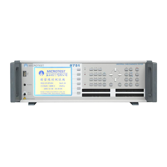
- Page 1 8751/8761 4-Wire Universal Cable/Harness Tester User Manual Version: 1.00 Issued Date: May, 2017...
- Page 2 Table of Contents Chapter 1 Cautions ............................3 1.1 Safety Symbols ..........................3 1.2 Avoid Self-Modification or Calibration ................... 3 1.3 Static Electricity ..........................3 1.4 Ground ............................. 3 1.5 Power Supply ........................... 3 1.6 Warming-Start ..........................4 1.7 Device Malfunctions ........................4 1.8 Unexpected Termination during Test Process ..................
- Page 3 APPENDIX B Test Range and Functions ....................79 APPENDIX C Technical Specifications ....................80 APPENDIX D Version ..........................81 Microtest Corporation all rights reserved. Declaration: Microtest Corporation reserves the right to modify the contents of this manual without further notice!
-
Page 4: Chapter 1 Cautions
1.2 Avoid Self-Modification or Calibration Never install surrogate parts onto the machine or undertake any device modifications and internal calibrations yourself without the express permission of Microtest, as you may increase the levels of danger associated with the device or damage the device. -
Page 5: Warming-Start
compatible with relevant safety regulations. Always check before use to ensure A/C power supply and voltage values are between 100V-240V @ 50/60Hz. 1.6 Warming-Start The testing device can be used normally immediately after switching the power on, but will not meet accuracy specifications unless allowed to warm up for 30 minutes. -
Page 6: Chapter 2 General Summary
Chapter 2 General Summary 2.1 Package and Accessories Standard accessories included in the 8751/8761 series tester package should include the following items: 1 x 8751 4-Wire Universal Cable/Harness Tester 2 x 64 moving needle type boxed connector (128P) ... -
Page 7: Operating Basics
2.3 Operating Basics Alphanumeric input Alphanumeric characters need to be inputted when saving files; the design used for this system is EditKey. The first time it is pressed, it will be numbers, and the 2 time will be the capital English letter from the left to the right on top of the number buttons respectively;... -
Page 8: Front And Rear Panel Displays
2.4 Front and Rear Panel Displays 2.4.1 Front Panel 64 and 128 models ○ ○ ○ ○ ○ ○ ○ ○ ○ ○ ○ ○ LCD display S1~S6 operation auxiliary buttons (Soft Key) PASS & FAIL & HIPOT LED Control button (Edit Key) group Test shortcut button group System reset (Reset) button Power switch... - Page 9 256 model ○ ○ ○ ○ ○ ○ ○ ○ ○ ○ ○ ○ ○ LCD display S1~S6 operation auxiliary buttons (Soft Key) PASS & FAIL & HIPOT LED Control button (Edit Key) group Test shortcut button group System reset (Reset) button Power switch Pin Search connector 256Pin has 8 slots...
-
Page 10: Rear Panel
2.4.2 Rear Panel 128 model: ○ ○ ○ ○ ○ ○ ○ ○ (1) Serial port (RS-232 Port) (2) Remote control port (Remote Port) (3) Printer Port (4) High voltage calibration output connector (5) AC power input (230/115 VAC) (6) 115/230V switch (7) Fuse holder 250V/3A (8) Audio output socket Note:... - Page 11 256 model: ○ ○ ○ ○ ○ ○ ○ (1) Serial port (RS-232 Port) (2) Remote control port (Remote Port) (3) Printer Port (4) AC power input (230/115 VAC) (5) 115/230V switch (6) Fuse holder 250V/3A (7) Audio output socket Note: 1.
-
Page 12: Block Diagram Of Tester Functions
2.5 Block Diagram of Tester Functions [Mode] [TEST] Comprehensive Test mode setting test [Func] Mode Conduction Test Function setting setting Yes/No [Setup] Mode DC insulation System setting Test setting AC tolerance Yes/No setting [Stat] Statistical data R setting Test Yes/No [Print] Print setting C setting... -
Page 13: Installation
(2) Connect the connector and test cable according to usage needs. (3) Turn on the power; the system will execute the self-test program. (4) When the execution of the self-test is completed, it will officially enter the 8751/8761 system; the LCD display will be as follows: (5) To end the system, please press the [Power switch] to end. - Page 14 Power on screen shortcut buttons: Makes the backlight of the LCD brighter Makes the backlight of the LCD darker Increases the volume level Decreases the volume level Software version and update date display Switch between Chinese/English Quickly switches to the short circuit table function (same as [O/S]) Quickly switches to the learning function (same as [Learn]) Quickly switches to file manager (same as [File]) Quickly switches to conductance edit function (same as [Cond])
-
Page 15: Button Usage Instructions
2.7 Button Usage Instructions 【1】 System (Sys Key) button group [Func] System function menu [Sys] System setting menu [Print] Print function menu 【2】 Test shortcut (Fast Key) button group [File] File manager setting [Learn] Short circuit learning [Stat] Display test statistics data [Mode] Test mode setting [O/S] Short circuit table display... -
Page 16: Chapter 3 Function Setting And System Setting
Chapter 3 Function Setting and System Setting The function settings and analysis modes include main system functions [Func], system settings [Setup] and print function [Print]; descriptions are as follows: 3.1 Function Menu Provides the main function menu for the system; its operations and function descriptions are as follows: (1) Press [Func]. -
Page 17: System Self-Test
3.1.1 System Self-Test This function allows the setting for whether this machine will execute the self-test function immediately upon powering on. (1) Press [Func]; please use [↑] or [↓] to select system self-test and then press [Enter]. (2) The system will now execute the self-test function. (3) The LCD screen will display as follows: (4) Press [Exit] to exit. -
Page 18: Ram Configuration Table
3.1.2 RAM Configuration Table This item allows the viewing of the 8751/8761 machine and version information; it lists the machine’s model number, test pins, total space used by files and the total remaining space etc. And it can perform system update. - Page 19 (4) Press [Exit] to exit. DC High Voltage Calibration The DC high voltage calibration is used to adjust the Read (test value) closest to the DC setting value. (1) Press [Func]. (2) Please use [↑] or [↓] to select test parameter calibration and then select DC high voltage calibration and press [Enter].
- Page 20 (4) Press S1 [increase] or S2 [decrease] to adjust the Read (test value) closest to the DC setting value. Or S5 for automatic adjustment. (5) When setting is complete, please press S4 [Save]. (6) To cancel the set data, simply press S6 [Cancel]. AC High Voltage Calibration The AC high voltage calibration is used to adjust the Read (test value) closest to the AC setting value.
- Page 21 press [Enter]. (3) The LCD screen will display as follows; skip directly to Step (6) for 8761. (4) Press [Enter] to execute the internal resistance offset action (when you want to execute internal resistance offset, please first insert the COND. OFFSET board). (5) If PORT A (slot A) completed internal resistance offset, the LCD will display a message asking whether to continue to offset the internal resistance of PORT B (slot B).
-
Page 22: Pin Search
(4) Press S1 [UP] or S2 [DOWN] to adjust the Read (test value) closest to the current output setting value. (5) When setting is complete, please press S4 [OK]. (6) To cancel the set data, simply press S6 [QUIT]. 3.1.4 Pin Search This function can display which is the current output pin. -
Page 23: Meter Mode
(5) A20 in the figure represents the 20th pin of slot A. 3.1.5 Meter Mode This function allows selecting of Conductance, R/L/C/D, Insulation, Withstanding, and use the meter mode to perform continuous tests. (1) Press [Func]. (2) Please use [↑] or [↓] to select meter mode and then press [Enter]. (3) Select the test item (Conductance, R/L/C/D, Insulation, Withstanding) and press [Enter]. - Page 24 3.1.5.1 Meter Mode - Conduction This function allows performing of conduction test. pin+: connected pin + selection. pin-: connected pin - selection. OFFS: Compensation value setting. The LCD screen will display as follows: 3.1.5.2 Meter Mode - Component This function allows performing of component (R: resistance L: inductance C: capacitance D: diode) measurement.
- Page 25 3.1.5.3 Meter Mode - Insulation This function allows performing of insulation test (one to other); press the high voltage switch to send high voltage and perform test. ※Beware high voltage: Press the high voltage switch and the Vdc shows ON, and the H.V.
- Page 26 3.1.5.4 Meter Mode - Tolerance This function allows performing of tolerance test (one to other); press the high voltage switch to send high voltage and perform test. ※Beware high voltage: Press the high voltage switch and the Vac shows ON, and the H.V. signal on the panel turns on, which means that high voltage is being sent to the straight boxed output terminal and the high voltage calibration terminal.
-
Page 27: Networking Fixture Setting
3.1.6 Networking Fixture Setting This function allows setting of the networking fixture (optional purchase) to perform internet connection. Protocol: Select TCPC or TCPS. Sever IP: Server IP address. Sever port: Server port. Host Address: Host address. Host mask: Host mask. Host gateway: Host gateway (gateway). -
Page 28: System Setting (Sys)
3.2 System Setting (SYS) System setting includes system configuration and test related action settings; their operation and function descriptions are as follows: (1) Press [Sys]. (2) The LCD screen will display as follows: Please use [↑] or [↓] to select the item needed and then press [Enter]. Press [Exit] to exit when completed. -
Page 29: Setting The Operating Environment
3.2.1 Setting the Operating Environment (1) The LCD screen will display as follows: (2) Please use [↑] or [↓] to select the item needed. (3) If needed, please press S1 or ←→ [PROG] to switch. (4) Press [Exit] to exit when completed. (1) Power on Self-Test There is a total of two options: The default value is │On│. - Page 30 please first go to system settings to change the system password and then go to key lock and select | Lock | before this function can be used. Note: 1. A password must be entered when the release key lock protection is selected, so please read the user manual carefully.
-
Page 31: Setting The Testing Environment
3.2.2 Setting the Testing Environment (1) The LCD screen will display as follows:... - Page 32 (2) Please use [↑] or [↓] to select the item needed. (3) If needed, please press S1 or ←→ [PROG] to switch. (4) Press [Exit] to exit when completed. (1) Tester ID Allows assigning an ID for this tester. (2) Test Alarm This function provides alarms for test results;...
- Page 33 Single file: Current file test (which is the {Current file} displayed on the main screen). Step file: Step file selection test. Auto: Use step file test when there are step files, and use current file test if there are none. (9) Step Test Fail Processing method to use when the step file test failed.
-
Page 34: Set System Time
Alone: Display and output test result for each step. Combined: Unified display of test results. (20) PC Link Cmd The connection program used (Microtest official) must be “On”. (21) Test Counter A prompt will appear when the number of tests has been reached when enabled; which means that it has reached the number of times set. -
Page 35: Change System Password
(3) The LCD screen will display as follows: (4) The time format is MM/DD/YY; please press S1 [Setting] to save when input is complete. (5) Press [Exit] to exit. Note: 1. Hour is in 24 hour format. 3.2.4 Change System Password This tester provides key lock protection in order to prevent data from being modified randomly. -
Page 36: Print Function Menu
If you are setting the password for the first time, enter the new password directly. If you have previously set a password, then you must first enter the original password and press [Enter]. Then enter the new password again and press [Enter]; the screen will display {Successfully set} at this time. - Page 37 (2) Enter circuit edit and the LCD screen will display as follows: (3) Press add network, add the network 001 short circuit pin A01, and the LCD screen will display as follows: (4) Press add pin and use the other function button (slot A) and the number button (02) to add the A02 pin; the LCD screen will display as follows:...
- Page 38 (5) Press check network (use the left and right buttons to move to the Net section) to check that there are no errors; the LCD screen will display as follows: (6) Press arrange network and then the exit button to complete network editing; the LCD screen will display as follows: (7) When check failed resulting in the network cannot be arranged and the network editing process cannot be completed, press the exit button after the prompt appears on the screen to return to the network...
-
Page 39: File Management (File)
3.5 File Management (File) For section 3.5 File Management (File), please refer to Chapter 4 Comprehensive testing mode, 4.3 File Management for details. 3.6 Statistical Data (Statistic) This function allows viewing of the test result statistical data, including: total number of tests, number of passes, number of fails and cause of failure analysis, which searches for the number of fails in each item category. -
Page 40: Mode Setting (Mode)
(3) Press S1 [QTY. RATE] to display the statistical data using percentages. (4) The LCD screen will display as follows: (5) Press S6 [CLR.] to clear all current statistical data. (6) Press [Exit] to exit when completed. 3.7 Mode Setting (Mode) Press [O/S] and then press S6 [O/S EDIT] to enter test mode setting. - Page 41 Applicable to general models: Applicable to Type C models: O/S Threshold: Available options include 2K, 5K, 10K, 20K and 50K; other functions are used to determine the short circuit value. If it is set as 2K, cables with resistance under 2K are considered to be short-circuited and with resistance above 2K are considered to be open circuit.
- Page 42 Maximum allowable capacity (MAX. Capacitance): Can be set between 0.05u~1u. This value should be set to a great number when the cables are longer in order to have stable tests. Short circuit pin determination (IDENTIFY O/S ENDS): Determine which pins are open circuit or short circuit.
- Page 43 When performing cable test, press [TEST] and the LCD screen will display as follows: From the LCD display screen, we can find out the total number of tests and the number of passes and fails. When test mode is being set, set the cable type as {SINGLE STEP}.
- Page 44 Press [Learn], the LCD screen will display as follows: Use the automatic pin search probe to specify the short circuit pin to test; example is as follows: When using the pin search probe on the panel, touch the relative position (A01) specified by the cable and the LCD will display that pin.
- Page 45 Place the probe sequentially on the pins specified by the cables (A03, A05, A07) and also press S1 [READ]; press S4 [Finish] when completed. When performing cable test, press [TEST] and the LCD screen will display as follows: Please use the automatic pin search probe and place it on A01; the LCD screen will display as follows:...
- Page 46 The automatic pin probe must be placed on A03, A05, and A07 sequentially in order to complete the cable test action. Since we initially have 4 steps preset, so for the test of each test DUT, steps 1 to 4 of the step test must be completed successfully in order for it to pass.
- Page 47 The value displayed at the right of the screen is the unilateral test sensitivity; S5 unilateral offset can be pressed and the value will change to zero after learning. S4 clears the unilateral offset value. Press [Learn] after inserting the test DUT, the LCD screen will display as follows: When test mode is being set, enter the value needed for the single side sensitivity.
- Page 48 When performing cable test, press [TEST] and the LCD screen will display as follows: From the LCD display screen, we can find out the total number of tests and the number of passes and fails. (3) Maximum capacitance: Can be set between 0.05u~1u; this value should be set to a great number when the cables are longer in order to have stable tests.
-
Page 49: Multiple Simultaneous Test Dut (Miltidut)
method; it allows setting of the number of times to test. (7) When there is error during test: If errors occur during test, there are three options displayed at all times: {Stop test}, {Do not test high voltage} and {Finish all tests}. (8) Short circuit pin determination: This is able to display the index display for the A Port or B Port short circuit. - Page 50 Select Yes, set the start and end of the test DUT according to the pin learned; a maximum of 4 tests can be selected and the start and end pins of the test DUT can be set. (P.S There must be no other test DUT at the start and end of the test DUT).
-
Page 51: Test Item (Item)
3.7.2 Test Item (Item) Press Mode. Press Test item. (1) Please use [↑] or [↓] to move to the item you want to set. (2) Press S1 [PROG] to switch whether to execute test for the selected item. Chapter 4 Comprehensive Test Mode Test mode uses programmed design functions, to perform simultaneous and automatic tests according to the different test conditions set for different test items, in order to satisfy different needs and achieve optimal efficiency;... -
Page 52: Test Condition Setting
Test condition setting. Comprehensive test implementation. File management. Detailed descriptions are as follows: 4.1 Test Condition Setting This part refers to the setting of some control standards and corresponding test conditions for the test DUT (DUT), including O/S / Cond / R / C / HIPOT / Diode settings; its contents mainly includes. ●... - Page 53 (2) The LCD screen will display as follows: (3) Please use [↑] or [↓] to select the item you want to set. Maximum conductance value (Max. Conductance): Please use the number buttons to enter a value according to your needs as the upper limit of the cable conductance. Minimum conductance value ((Min.
- Page 54 Press S3 [Cond Net] to enter conduction edit: Press S1 [SET] the item needed and then press S4 [OK]: Import to component edit:...
-
Page 55: R/C/D Component Setting Edit (Resistance)
Cable off: After inserting the offset fixture, press S5 [Cable offset] to perform offset, and the cable offset located at the bottom left will display: Yes. Clear offset: Press S6 [Clear offset] to clear the previous conduction value, and the cable offset located at the bottom left will display: None. - Page 56 (4) After the cursor moves to the standard value line, enter the actual test value or use S1 [Learn] and S2 [Learn all] function; the LCD screen will display as follows: (5) When the component is resistance or capacitance, press S5 [CLR. OFFS] to offset; the LCD screen will display as follows:...
- Page 57 (6) Press [Enter] to perform the offset action. (7) Press S6 [All SAME] to clear the data used for resistance or capacitance offset. (8) When the component is resistance, press SHIFT+S5 [CLR. OFFS] to display the data for resistance offset; the LCD screen will display as follows: (9) When the component is diode or current leakage, press S3 [SET PARA] to perform parameter setting;...
- Page 58 (9.1) For diode parameter settings, the test mode can be switched and the test current value can be entered; the LCD screen will display as follows: (10) Item descriptions are as follows: Name Please enter the name for the resistance test group set. +Pin (Positive pin) ...
-
Page 59: High Voltage Setting Edit (Hv)
4.1.4 High Voltage Setting Edit (HV) This function is the setting for DC insulation, test voltage for AC tolerance, frequency, time, specification, and other items. (1) Press [HV]. (2) The LCD screen will display as follows: " (1) Please use the direction button sot move to the item you want to set. (2) Enter your specification control standard value. - Page 60 Test Specification Sets the test specification of the DC insulation and AC tolerance test; the DC insulation specification can be set between 0.1MΩ~1000MΩ, 0.1uA~1000uA. ※When the setting is set as 5MΩ or below 5uA, the maximum test voltage is 650V and the AC tolerance specification can be set between 0.01mA~5mA.
- Page 61 leakage or insulation value and so on. High voltage is connected to each pin while other pins are grounded to observe their current leakage or insulation value. This way it can confirm that all the test pin high voltage insulation test have no problems, and the number of tests for this method is N-1 times. This test method is more accurate and it can find the insulation and current leakage value for each pin;...
- Page 62 V ramp Time Sets the voltage increase time for the DC insulation and AC tolerance test. The increase time for the voltage of the DC insulation test can be set between 0~64 phases, the smaller the setting value the faster it increases.
-
Page 63: Comprehensive Test Implementation
4.2 Comprehensive Test Implementation After the settings above are completed, comprehensive test implementation can be performed. Since the operating procedures are different, it can be divided into two types: Real time test and Existed test; individual descriptions are as follows: 4.2.1 Real Time Test This part sets the test conditions saved in the main memory as the test condition and performs test to test DUTs in real time. -
Page 64: File Management
(6) Press [Mode] to display the test mode setting screen. (7) Check and confirm whether the test mode settings are correct, and change according to your needs. (8) After confirming there are no errors, press [EXIT] to exit and return to the main screen. (9) Press [TEST] to start testing. -
Page 65: Step Setting
(6) At this time the LCD screen will return to the main screen and the name of the file you selected will be displayed for current file; file loading has been completed at this time. 4.3.2 Step Setting When you need to perform multiple test steps to a test DUT, you can set the test steps that need to be performed using step test, to simplify your test process and reduce your test time. - Page 66 (4) Use [↑] or [↓] to move the cursor to select and set the test steps needed to be performed to the test DUT. (5) For example: We selected the three files EX1, EX2 and EX3. (6) Use [↑] or [↓] to move the cursor to EX1, and then press S3 [SET]. (7) The LCD screen will display as follows: And then use [↑] or [↓] to move the cursor to EX2, and then press S3 [SET].
- Page 67 (11) Please press S4 [Finish] and the LCD screen will display as follows: (12) This way step test setting is complete; S2 [LEARN] can also be used for setting. (13) For example: Put the test DUT in place and press S2 [LEARN]; the LCD screen will display as follows:...
- Page 68 (14) Press S1 [LEARN] and the 1st step setting will be generated; the LCD screen will display as follows: (15) And so on, we can set the 1st, 2nd... step. Assume we have set a total of 5 test steps, once setting is completed, press S3 [OK] and the LCD screen will display as follows:...
- Page 69 (16) This also completes the setting for step test. (17) Press S3 [STEP TEST] or [TEST] and the LCD screen will display as follows: (18) Performs the 1st test step, the LCD screen will display as follows:...
- Page 70 (19) First step PASS, the LCD screen will display {Wait for test step 2}. (20) And so on until all 5 steps set are completed, the LCD screen will display as follows: (21) This completes the step test. Note: 1. When each test step is completed, the machine will scan for short circuits (O/S).
-
Page 71: Create New File
4.3.3 Create New File The function to create a new file in the permanent memory; its instructions are as follows: (1) Press [File]. (2) Press S2 [NEW] to perform the create new file action. (3) The LCD screen will display as follows: (4) Enter file name. -
Page 72: Upload All
(4) Confirm the file name you want to upload and press [Enter] to complete the upload file action. 4.3.5 Upload All Upload all uploads all the files to the USB flash drive; its instructions are as follows: (1) Press [File]. (2) Press S4 [UP ALL] to execute the upload all files action. -
Page 73: File Sorting
(2) Press S5 [DEL.] to execute the delete file action. [SHIFT] + S5 S5 [DEL.] deletes all files. (3) The LCD screen will display as follows: (4) Confirm the file name you want to delete and press [Enter] to complete the delete file action. 4.3.7 File Sorting File sorting sorts the files according to four rules ();... - Page 74 Press S6 [SORT] to execute the file sort action. File order after sorting.
-
Page 75: Import File
4.3.8 Import File Import file imports files on the USB flash drive to the tester; its instructions are as follows: (1) Press [SHIFT] + [File]. (2) The LCD screen will display as follows: 1. Enters the import file screen. 2. Press S1 [PROG] or S4 [SEL ALL] to select the file to import; on the other hand you can press S5 [CANC EALL] to cancel the selected files. - Page 77 APPENDIX A Cable Wiring Configuration RS-232C CABLE Baud Rate:115200bps Character Length:8bits Stop Bit:One Bit Parity:Non-Parity Character:ASCII Character Function 8751/8761 C o n t ro l l e r Pin2 Pin3 Pin3 Pin2 Pin5 Pin5 PRINTER CABLE 25-PIN 36-PIN connector Signal...
- Page 78 8751/8761 REMOTE 15-PIN connector CTL0 EGND CTL1 CTL2 CTL3 RESET CTL4 CTL5 +12D CTL6 EGND CTL7 EGND + SW1 Short circuit means test can be started (same as pressing [TEST] on the panel). EGND+ SW2 Short circuit means exit (same as pressing [Exit] on the panel).
- Page 79 Multiple test DUT simultaneous test signal Multiple DUT CTL0 Start test CTL1 High voltage testing CTL2 Total PASS status CTL3 Total FAIL CTL4 DUT 1 FAIL status CTL5 DUT 2 FAIL status CTL6 DUT 3 FAIL status CTL7 DUT 4 FAIL status ※+5D and +12D output current must not exceed 100mA.
- Page 80 APPENDIX B Test Range and Functions Item Symbol Test range Error range Minimum test voltage Resistance ±10% 0-1Ω ±5% >1Ω && <10Ω >10Ω && <100Ω ±2% ±2% >100 && <1KΩ >1KΩ && 10KΩ ±2% >10KΩ && <100KΩ ±2% ±2% >100KΩ && 1MΩ ±2% >1MΩ...
- Page 81 Test scan mode Switchable automatic/short circuit scan Test signal source Low voltage test signal Rated output 5Vdc ±5% accuracy DC insulation/AC tolerance test range 8751/8761-FA 50~1500VDC / 100~1000VAC 8751/8761-NA 50~1000VDC / 100~700VAC 8751/8761-NAC 50~1000VDC / 100~700VAC 8751/8761-N 50~1000VDC / ----------------- 50V Resolution ±5% accuracy...
- Page 82 Remote control port USB port (test result/test setting file/system update) Memory device Built-in 2048KB SRAM A maximum of 250 sets of test setting files can be saved Built-in CR2032 battery Power supply 115/230 Vac switchable voltage input±10% 60/50Hz APPENDIX D Version 2017/05/24 V1.0 Original issue...
Need help?
Do you have a question about the 8751 and is the answer not in the manual?
Questions and answers