Table of Contents
Advertisement
Quick Links
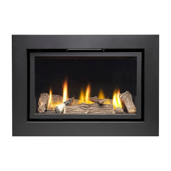
Vola 600HE
Vola 6x6HE
Also, known as
Ignite Pinnacle 600 / Apex 600
Ignite Pinnacle 6x6 / Apex 6x6
Installation and User Instructions
INTEGRATED SUITE INSTRUCTION ARE SEPARATE
AND MUST BE READ IN CONJUNCTION WITH THESE
INSTRUCTIONS BEFORE INSTALLATION STARTS
All instructions must be handed to user for safekeeping
This is not a DIY product and must be installed by a Gas Safe
registered installer
Edition C 06/17
Country(s) of destination - GB/IE
1
Advertisement
Table of Contents

Related Manuals for Vola 600HE


Summary of Contents for Vola 600HE
- Page 1 Vola 600HE Vola 6x6HE Also, known as Ignite Pinnacle 600 / Apex 600 Ignite Pinnacle 6x6 / Apex 6x6 Installation and User Instructions INTEGRATED SUITE INSTRUCTION ARE SEPARATE AND MUST BE READ IN CONJUNCTION WITH THESE INSTRUCTIONS BEFORE INSTALLATION STARTS...
- Page 2 INSTALLATION INSTRUCTIONS These Notes Must Be Read Before Installation The appliance is designed to fit most types of fireplaces with a natural draught flue as listed in the Installation Requirements. The appliance must be installed by a competent person in accordance with the Gas Safety (Installation and Use) Regulations 1998.
- Page 3 OPENING THE APPLIANCE Stand the carton the right way up, open the box from the top. Read all the instructions before continuing to unpack or install this appliance. Remove the bags containing ceramic components such as coals or gravel etc. Remove the cardboard packing pieces, and any other bags or boxes containing fittings or other parts.
-
Page 4: Table Of Contents
INSTRUCTION CONTENT Section Contents Page No Important Notes Installation requirements Appliance Information Ventilation Site Requirements Pre-Fabricated Flue box Debris Space Installation of appliance Preparing the Opening Fitting the Burner Tray Fuel Bed Fitting the Outer Frame/ Trim Commissioning the Appliance 10.1 Spark Failure Setting Pressure... -
Page 5: Important Notes
Section 1: IMPORTANT NOTES This fire is an Inset Live Fuel Effect Gas Fire providing radiant and convected heat, it is designed to operate on Natural Gas. It is the LAW that all gas appliances and fittings are installed by a competent person such as a Gas Safe Registered fitter and in accordance with the Gas Safety (Installation and Use) Regulations 1998, the relevant British Standards for Installation, Codes of Practice and in accordance with the manufacturers’... -
Page 6: Installation Requirements
Section 2: INSTALLATION REQUIREMENTS This appliance MUST NOT be installed into a bathroom or shower room, or where steam may be present. An extractor fan must not be fitted in the same room or space as the appliance as this can affect the safety of the appliance. -
Page 7: Appliance Information
Section 3: APPLIANCE INFORMATION H.E Landscape Gas Group G20 Natural Gas CAT I2H Inlet Pressure 20 mbar Max Input (gross) 5.0 / 5.6 (6x6) Min Input (gross) 2.3 / 3.0 (6x6) Setting Pressure 20 mbar Gas Inlet connection 8mm Compression Overall Height 514 / 674 (6x6) Overall Width... -
Page 8: Ventilation
Section 4: VENTILATION This Appliance does not normally require purpose provided ventilation. However, a second appliance operating within the same room or space must be taken into consideration when assessing ventilation. When commissioning the appliance spillage is detected, then amongst other problems there may be insufficient natural ventilation for correct operation of the flue. - Page 9 From the appliance to underneath of a Shelf with a depth of 150mm is 350mm add 12.5mm in height for every 25mm increase to the projection of the shelf depth. Suite Option When used in conjunction with a fireplace suite of marble or stone the height of the appliance will need to be adjusted to match the individual suite specifications, please refer to suite manufactures instructions and guidelines where applicable, if a custom suite has been produced then please seek the advice of the installer of the suite for height requirements.
- Page 10 The Greener Company Vitcas Huddersfield Road, Elland, WEST YORKSHIRE HX5 0EE 8 Bonville Road, Brislington, Bristol BS4 5NZ www.thegreenercompany.com http://www.vitcas.com Opening Requirements Width 610-645mm 455-470mm Height 615-630mm (6X6) Depth 340mm minimum From Floor 300-Minimum...
-
Page 11: Debris Space
Section 5.1: PREFABRICATED FLUE BOXES These appliances can be fitted to a prefabricated flue system, a chamber to enclose the appliance should be created with the prefabricated flue placed and sealed at the top of the chamber and construction should be of a non-combustible material. - Page 12 ease of access to the fire box and the burner, start by removing the ceramic pads over the burner and gentle put this to one side to avoid any damage. Remove the access panel and undo the isolation connection. Next remove the screws in each corner,...
- Page 13 Next undo the nut connecting the burner to the isolation valve and tray will now lift free of the firebox. If you are to use with a suite or as a frameless option then the Isolation tap needs to be repositioned. Burner tray showing standard bracket Burner tray with frameless bracket option 1.
-
Page 14: Preparing The Opening
Section 7.1: PREPARING THE OPENING Before installing the fire, check the flue for correct operation using a smoke pellet, all of the smoke should be drawn up the flue and exit correctly from the terminal. If problems are found DO NOT fit the fire until corrective measures have been completed. - Page 15 With the frameless option a power lead needs to be routed through a conduit or sleeved into the opening and into the fire at the rear, taking care to keep the cable, as shown in the diagram below insuring that it is lying flat and away from the hot surface of the burner and components. Frameless options must only use mains power and batteries must NOT be used •...
-
Page 16: Fitting The Burner Tray
Section 7.3: FITTING THE BURNER TRAY Prior to the traying being placed in position if being used with a frameless kit then a manual override kit needs to be fitted. 1. Place the screws into the holes of the key mechanism and fix to the bracket on the remote- control valve When fitting the frameless back panel with this installation ensure the keys fit above the panel as shown in Fig 2... - Page 17 Press to Decrease flame To Increase Flame Power Button The key mechanism will now give you manual control of the remote valve as shown above The keys have a small movement of approx. 1mm. The tray may now be placed in to position reversing the removal instructions taking care with all ceramic parts.
- Page 18 WHEN FIXING THE GLASS BACK INTO POSITION PLEASE PUT ALL THE SCREWS IN HALF WAY AND THEN TIGHTEN FULLY INTO PLACE TO AVOID TWISTING THE FRAME. With the burner tray fixed in place the sub frame for the frameless can be fitted as shown below, care must be taken to get this into the correct position as you can see in Fig 3 the bottom area of the subframe sits level to line up the manual control mechanism and the heat outlet at the top has a clear area see Fig 4.
- Page 19 When using the appliance in conjunction with a fireplace suite, you can use either non-combustible slips like stone granite or marble, or a sirocco metal back panel, please see www.siroccofires.com for further details on the metal back panel. Main Firebox Front fascia panel always ensure that the fascia is fitted in the correct position as in correct fitting this may result in the appliance...
- Page 20 Section 8: LINING REPLACEMENT To remove the lining for colour change or replacement, with the tray removed the top place can be removed by the two brackets in place on either side, then gentle remove the side sections and the back to fit simply reverse the process.
- Page 21 Section 8.1: FUEL BED LAYOUT Cover the base with Vermiculite provided making sure NOT to block the burner outlets and keeping an area around the pilot clear to help when cross lighting of the fire. Evenly place a layer of the stainless-steel wool provided over the burner loosely to give the burning embers effect Now Place each piece as per the pictures some adjust will be needed to ensure the flames go in between the pieces and NOT to be placed directly above the flames as this will create carbon deposits.
-
Page 26: Commissioning The Appliance
Remember some adjust will be needed to ensure the flames go in between and around the pieces and to be placed directly above the flames as this will create carbon deposits. WHEN FIXING THE GLASS BACK INTO POSITION PLEASE PUT ALL THE SCREWS IN HALF WAY AND THEN TIGHTEN FULLY INTO PLACE TO AVOID TWISTING THE FRAME Section 10: COMMISSIONING THE APPLIANCE Turn on and test the gas supply up to the fire for any leaks, in accordance with current Approved Codes... - Page 27 Section 11: SETTING THE GAS PRESSURE Remove the pressure test point sealing screw from the isolation elbow and attach a suitable pressure gauge. Check that the inlet gas pressure is at 20 mbar / Working Pressure at 20 mbar (+/- 1 mbar) Light the pilot and check the correct operation of the burner at all the flame settings.
-
Page 28: Testing For Spillage
SECTION 13: TESTING FOR SPILLAGE CHECKING FOR CLEARANCE OF COMBUSTION PRODUCTS Close all doors and windows in the room light the fire and allow to run for approximately 5 minutes on high position. After approximately 5 minutes, hold a smoke match just inside and below the centre of the lower front edge of the top of the fire, as shown below in Fig 1. -
Page 29: Briefing The Customer
SECTION 14: BRIEFING THE CUSTOMER • All instructions must be handed to the user for safekeeping. • Show the customer how to light and operate the fire. • After commissioning the appliance, the customer should be instructed on the safe use of the appliance and the informed for the need of regular servicing. -
Page 30: User Instructions
SECTION 16: USER INSTRUCTIONS IMPORTANT NOTES The installation of this fire MUST only be carried out by a competent person (such as a Gas Safe registered fitter) in accordance with the Gas Safety (Installation and Use) Regulations 1998, the relevant British Standards, Codes of Practice, the Building Regulations and the manufacturers’ instructions. - Page 31 SECTION 17: OPERATING THE APPLIANCE (Remote Control) The Remote Control with this appliance has already been paired at the Factory Quick start user instructions Fire Control This control is situated on your fire. The drawing shows the main features of the control. The control required 3 x AA size alkaline batteries to be inserted under the battery compartment cover.
- Page 32 The Valve and Handset Have Already Been Paired First set up the hand set, cup the handset the green unlock light will illuminate. Keep it held to keep the control unlocked, to enable operation of the buttons. 3) Setting the time, the display will be as shown, as the time is not set yet and will progress automatically to the next screen shown below.
- Page 33 Setting the day of the week Press and release the + and – buttons until the correct day of the week is shown on the display. (Mo = Monday, Tu= Tuesday, We=Wednesday, Th=Thursday, Fr=Friday, Sa=Saturday and Su=Sunday). Press “SET” to accept the day of the week and to progress to setting the Hour of the day. Note: Whilst doing this setup pressing “SET”...
- Page 34 Quick start user instructions First set up the hand set, cup the handset the green unlock light will illuminate. Keep it held to keep the control unlocked, to enable operation of the buttons. Then with the other hand touch and keep you finger on the power button for about 5 seconds. (Upon touching the power button the green light will do a single flash to show command is recognized –...
- Page 35 this system, the control has been designed to ensure that only intended ignition of the fire occurs.) To stop – with handset held to unlock it, press then release power button. Mode In Range of the fire Man = Manual If missing out of Zzz = Snooze range or fire...
- Page 36 Operating instruction (Detailed) 1) Upon successful insertion of the batteries in the Handset (if the handset has not previously paired) the display will be as shown if it has been paired already then go to No 3. 1a) If display is not as above the handset may well need to be reset before pairing. Press and Hold “Set”...
- Page 37 to operate the fire control. Whilst the display is as shown, and holding the handset as described, press the “SET” button with the other hand to finish off the pairing of the handset to the Fire Control and to enter to setup the time of day on the handset. N.B. If the display returns to the one shown above with the word “TESC”...
- Page 38 SECTION 17a: Remote Error Trouble Shooting Guide Code Comment Appearance Possible Cause Action Reset control by pressing start button for 1 second and releasing. The press Red Led is Temporary air again the same way to permanently on TESC locked due disturbance attempt a normal start TESC unit (and...
- Page 39 Pilot Change pilot or thermocouple thermocouple defective / old Possible temporary air Clear error and restart to disturbance on check ignition ok pilot flame Code Comment Appearance Possible Cause Action Occurs if started ok then subsequently loss of too high ambient Negative flue pull or thermocouple temperature (>73 °C)
- Page 40 Check to see if Jumpers on back of jumpers are in 10- Reset and try again valve missing way connector pressures switch Check pressure error caused by action connection or switch connections, external pressure jumpers missing or check to see if Reset and try again switch not connected...
- Page 41 Check for Clean as necessary. Replace button (-) is shorted contamination / switch panel as necessary if to other buttons damage and damaged or too contaminated. Reset and try either on TESC or on replace wired Disconnect wired control panel again wired control panel switch panel if...
- Page 42 Thermocouple Check and correct Thermocouple doesn't reach final Reset and try Replace Pilot wiring. Replace thermocouple if current - damaged again necessary or aged Check and correct Thermocouple Reset and try Check pilot connections wiring. Replace thermocouple if again necessary Pilot pipe may be blocked Reset and try Clear pipe, replace pilot as necessary...
-
Page 43: Cleaning The Coals
SECTION 18: CLEANING THE COALS • Open the glass door • Remove the ceramic components. • Gently clean in the open air using a dry paint brush. • Be careful not to create dust from the ceramics. • Where necessary replace damaged components with genuine spares. •... - Page 44 SECTION 19: WARRANTY IMPORTANT INFORMATION ABOUT WARRANTY SERVICE FOR THE END USER WARRANTY REGISTRATION IS REQUIRED WITHIN 28 DAYS FROM DATE OF PURCHASE It is in your interest to register your appliance with Sirocco as soon as possible BEFORE CONTACTING SIROCCO FOR SERVICE PLEASE READ THE FOLLOWING; Sirocco is committed to customer care and service.
- Page 45 SECTION 20: LIST OF SPARES Code Spares PART NUMBER Replacement glass panel with door Engine (remote) Excluding ceramics with Handset TESC Remote Gas Valve (Only) THERM Remote hand set THERM Remote assembly Thermaco ERTA NG OXI-PG-82-460 Therm Vermiculite chippings HT wire wool New Forest Log Set...
- Page 46 SECTION 21: CONTACT DETAILS GENERAL HELP LINE 08432 890102 Mon to Fri 9:00 to 16:00 SPARE PARTS If you need assistance or wish to purchase spare parts 08432 890102 Mon to Fri 9:00 to 16:00 Contact our spares department by email spareparts@siroccofire.pl Purchase spare parts direct from our website www.siroccofires.com...
- Page 47 Our warranty statement 5 YEAR WARRANTY STATEMENT You have purchased your new Sirocco appliance that has been made to the highest standards. When properly maintained and used the appliance will perform perfectly for many years, and is warranted for 12 months from date of purchase for parts and labour as covered by the terms and conditions of warranty, verification may be required of the defect by a Sirocco engineer, or a Sirocco appointed engineer, provided that such parts have been subjected to normal conditions of use.
- Page 48 This guarantee is none transferable and is made to the original owner, provided that the purchase was made through a company appointed stockist Any installation, labour, transportation or other related costs expenses arising from defective parts repair replacement or otherwise of same will not be covered by this guarantee nor shall the company assume responsibility for same. Furthermore, the company will not be responsible for any incidental, indirect or consequential damages except as provided by law.
- Page 49 COMPLETE THE FORM USING CAPITALS DATE OF PURCHASE AS IT APPEARS ON YOUR RECEIPT SERIAL NUMBER (WHICH IS SHOWN ON THE DATA BADGE OF THE APPLIANCE) MR MRS MISS INITIALS. SURNAME HOUSE NUMBER ADDRESS TEL NUMBER POST CODE EMAIL ADDRESS WHERE YOU PURCHASED YOUR APPLIANCE FROM NAME ADDRESS...
- Page 50 SIROCCO Sp. Zo. o PLEASE C/O UNIT 1 AFFIX STAMP THE WEIRS HERE 11 WEIR STREET BLACKBURN LANCASHIRE, BB2 2AN FOLD HERE...
Need help?
Do you have a question about the 600HE and is the answer not in the manual?
Questions and answers