Advertisement
Quick Links
FRENIC-VG 用
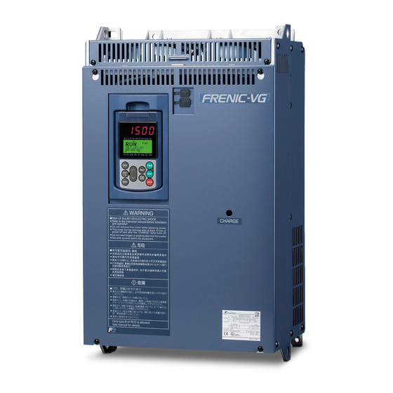
当社高性能ベクトル制御形インバータ FRENIC-VG シリーズ用Tリンクインタフェースカードをお買上げいただき
ありがとうございます。
- 間違った取扱いは,正常な運転を妨げ,寿命の低下や故障の原因になります。
- この取扱説明書は,実際に使用される最終需要家に確実にお届けください。
- この取扱説明書は,Tリンクインタフェースカードが廃棄されるまで大切に保管してください。
- この取扱説明書には機能コードの説明やトラブルシューティングの記載はありませんので,FRENIC-VG ユーザ
ーズマニュアルを合わせてご覧ください。
T リンクインタフェースカード
OPC-VG1-TL
- 1 -
INR-SI47-1596-JE
Advertisement

Summary of Contents for Fuji Electric OPC-VG1-TL
- Page 1 T リンクインタフェースカード FRENIC-VG 用 OPC-VG1-TL ...
- Page 2 まえがき T リンクインタフェースカード「OPC-VG1-TL」をお買上げいただきましてありがとうございます。 このインタフェースカードを FRENIC-VG に取り付けることで,富士プログラマブルコントローラ MICREX-SX シリー ズ(T リンクモジュール)と接続し,運転指令・速度指令・機能コードアクセス等を使って FRENIC-VG をスレーブと してコントロールすることができます。 このインタフェースカードは,FRENIC-VG のオプション接続ポートのうち,A-port または B-port に搭載可能です。 この取扱説明書には,このインタフェースカードに関連する機能コードの説明やトラブルシューティング,インバ ータおよび MICREX-SX シリーズに関する取扱い方の記載はありませんので,ご使用の前には,この説明書と共にイ ンバータ取扱説明書および FRENIC-VG ユーザーズマニュアルをお読みになって取扱い方を理解し,正しくご使用く ださい。間違った取扱いは,正常な運転を妨げ,寿命の低下や故障の原因になります。 取扱説明書はご使用後も大切に保管してください。 関連資料 OPC-VG1-TL に関連する資料を以下に示します。目的に応じてご利用ください。 ・ F RENIC-VG ユーザーズマニュアル ・ F RENIC-VG 取扱説明書 ...
- Page 3 ・ 部 品が損傷・脱落している製品を使用しないでください。 火災,事故,けがのおそれあり ・ 糸 くず,紙,木くず,ほこり,金属くずなどの異物がインバータやインタフェースカード内に侵入するのを防 止してください。 火災,事故のおそれあり ・ 製 品の取付け,取外し時に不適切な作業を行うと,製品が破損するおそれがあります。 故障のおそれあり 運転操作について ・ 必 ずインバータの表面カバーを取り付けてから電源を投入してください。なお,通電中は表面カバーを外さな いでください。 ・ 濡 れた手で操作しないでください。 感電のおそれあり ・ 機 能コードのデータ設定を間違えたり,取扱説明書およびユーザーズマニュアルを十分理解しないで機能コー ドのデータ設定を行うと,機械が許容できないトルクや速度でモータが回転することがあります。インバータ の運転の前に各機能コードの確認,調整を行ってください。 事故のおそれあり ・Tリンク経由や外部信号端子で運転指令を入れたまま通信有効/無効の切り替えを行うと,突然始動しますの で,運転指令が切れていることを確認してから行ってください。 ・Tリンク経由で運転指令を入れたままアラームリセットを行うと,突然再始動をしますので,運転指令が切れ...
- Page 4 第1章 ご使用の前に 1.1 現品の確認 ・ 部 品が損傷・脱落している製品を使用しないでください。 けがのおそれあり 製品がお手元に届きましたら,次の項目についてご確認ください。 (1) ご注文どおりの製品であるか,確認してください。本インタフェースカードに印刷されている形式をご確認く ださい。 形式: OPC-VG1-TL (2) 輸送時の損傷がないか,調べてください。 (3) 付属品が揃っているか確認してください。 ねじ(M3) :3 本 スペーサ :3 本 製品にご不審な点や不具合などがありましたら,お買い上げ店または最寄りの弊社営業所までご連絡ください。 本インタフェースカードには終端抵抗を付属していません。終端抵抗は次のものをご使用ください。 100Ω 1W。(MICREX-SX シリーズの T リンクモジュールに付属している終端抵抗器が使用できます。) 1.2 製品の外観 3- Φ 3.6 EP-4201- RSW1 RSW2...
- Page 5 1.3 使用上の注意 1.3.1 一時保管 表1.3-1 保管,輸送時の環境 項 目 仕 様 保存温度 -25〜+70℃ (注 1) 急激な温度変化による結露や氷結が生じない場所 相対湿度 5〜95% (注 2) 塵埃,直射日光,腐食性ガス,可燃性ガス,オイルミスト,蒸気,水滴,振動がないこと。塩分 雰囲気 があまり含まれないこと。 (年間 0.01 mg/cm 以下) 86〜106 kPa(保管時) 気圧 70〜106 kPa(輸送時) (注 1) 保存温度は,輸送程度の比較的短時間を想定した値を示します。 (注 2) 湿度が仕様値を満足していても,温度変化が大きな場所では結露や氷結が生じます。そのような場所は避けてくだ さい。 一時保管の注意事項 (1) インタフェースカードを床に直接放置しないでください。 ...
- Page 6 第2章 インタフェースカードの取付け 2.1 前カバーの取外し ・ 製 品の取付け,取り外し時に不適切な作業を行うと製品が破損するおそれがあります。 ・インタフェースカードの取付け,取外しは,インバータの入力電源を遮断し,チャージランプ(CHARGE)が消 灯してから行ってください。また,インバータの主回路・制御・補助電源のすべてを OFF(開)しても外部の制 御回路が別電源のときは,インバータの制御端子 30A,30B,30C,Y5A,Y5C には電源が印加されています。 ・ 感 電防止のために外部の電源も OFF(開)してください。 下図のようにインバータ本体の前カバーを取り外してください。なお,取り外し方法は適用インバータ機種(容量) により,異なりますのでご注意ください。 FRN22VG1S-2J/4J(22kW)以下の場合 FRN30VG1S-2J/4J(30kW)以上の場合 図 2.1-1 のように,a 部の表面カバー取付けネジ1ヶ所 (1) 図 2.1-2 のように, b 部の表面カバー取付けネジ (容 をゆるめ,表面カバーの上部を持って,取り外してくだ 量により個数は異なります)を外し,表面カバーを...
- Page 7 2.2 インタフェースカードの取付け 本インタフェースカードは,制御プリント基板上に 2 箇所あるコネクタ A-port(上側), B-port(下側)のうち,どち らかに接続します。 - 本インタフェースカードをデジタル 16bit オプション(OPC-VG1-SX など)と同時に使用しない場合は,以下の「取 付け方法1」に従ってください。 - 本インタフェースカードをデジタル 16bit オプション(OPC-VG1-SX など)と同時に使用する場合は,以下の「取付 け方法2」に従ってください。 注: 本インタフェースカードを2台搭載して使用することはできません。 取付け方法1(デジタル 16bit オプションと同時に使用しない場合) (1) 制御プリント基板のオプション取付け用金具の3ヵ所"a"〜"c"に,付属のスペーサ"d"(3 本)を取り付けます。 (2) 本インタフェースカードのコネクタ(CN1)が制御プリント基板のコネクタ(B-port)に接続するように,インタフ ェースカードを取り付けます。 (3) 付属のねじ"e"(3 本)を締めてインタフェースカードを固定します。 (4) 図 2.1-1,図 2.1-2 の「前カバーの取外し方法」を参照して,前カバーを取り外した手順と逆に取り付けます。 図 2.2-1 インタフェースカード取付け方法(B-port に取り付ける場合) ...
- Page 8 (1) 制御プリント基板のコネクタ(D-port)に,デジタル 16bit オプションを取り付けます。 (2) デジタル 16bit オプションの取付け用穴( 〜 )の と にデジタル 16bit オプション付属のねじ"a"(2 本) を, 〜 にスペーサ"b"(4 本)を取り付けます。 (3) 制御プリント基板のオプション取付け用金具"c"には, インタフェースカード付属のスペーサ"d"(1 本)を取り付 けます。 (4) 本インタフェースカードのコネクタ(CN1)が制御プリント基板のコネクタ(B-port)に接続するように,インタフ ェースカードを取り付けます。 (5) 付属のねじ"e"(3 本)を締めてインタフェースカードを固定します。 (6) 図 2.1-1,図 2.1-2 の「前カバーの取外し方法」を参照して,前カバーを取り外した手順と逆に取り付けます。 図 2.2-2 インタフェースカード取付け方法(B-port に取り付ける場合) 改定履歴 番号 改定年月 ...
- Page 9 - Deliver this manual to the end user of this product. Keep this manual in a safe place until this product is discarded. - This manual does not contain the description of function codes or troubleshooting information. Read through this manual in conjunction with the FRENIC-VG User's Manual. Fuji Electric Co., Ltd. INR-SI47-1596-JE - 1 -...
- Page 10 Keep this manual in a safe place. Related Publications Listed below are the other materials related to the use of the T-Link interface card "OPC-VG1-TL." Read them in conjunction with this manual as necessary. • FRENIC-VG User's Manual •...
- Page 11 • Prevent lint, paper fibers, sawdust, dust, metallic chips, or other foreign materials from getting into the inverter and the interface card. Otherwise, a fire or an accident might result. • Incorrect handling in installation/removal jobs could cause a failure. A failure might result.
- Page 12 Unpack the package and check the following. (1) The product is the type you ordered. You can check the model printed on the interface card Model: OPC-VG1-TL (2) The interface card is not damaged during transportation. (3) The following accessories are also contained in the package.
- Page 13 1.3 Precautions for Use 1.3.1 Temporary storage Table 1.3-1 Storage and Transport Environments Item Specifications Storage temperature -25 to +70˚C Places not subjected to abrupt temperature changes or condensation (Note 1) or freezing. Relative humidity 5 to 95% (Note 2) The interface card must not be exposed to dust, direct sunlight, corrosive or flammable Atmosphere gases, oil mist, vapor, water drops or vibration.
- Page 14 Chaper 2 INSTALLING THE INTERFACE CARD 2.1 Removing the Front Cover • Incorrect handling in installation/removal jobs could result in a broken produce. • Before installing or removing the interface card, shut down the input power to the inverter and make sure that the charging lamp is turned OFF.
-
Page 15: Installing The Interface Card
2.2 Installing the Interface Card The interface card should be connected to either one of two connectors A-port (upper side) and B-port (lower side) on the control printed circuit board (control PCB). - When using the interface card without the digital 16-bit option (e.g., OPC-VG1-SX), follow the "Mounting procedure 1"... - Page 16 T-Link interface card. Please feel free to send your comments regarding any errors or omissions you may have found, or any suggestions you may have for generally improving the manual. In no event will Fuji Electric Co., Ltd. be liable for any direct or indirect damages resulting from the application of the information in this manual.


Need help?
Do you have a question about the OPC-VG1-TL and is the answer not in the manual?
Questions and answers