Table of Contents
Advertisement
Available languages
Available languages
Quick Links
Quick Start Guide
Ethernet Switch
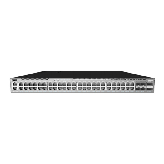
AS4630-54TE
1
1.
AS4630-54TE Switch
2.
Rack mounting kit—2 brackets and 8 screws
3.
2 x Power cord
4
1
2
3
1.
1x USB port
2.
1 x Management port
3.
1 x Serial console port
4.
System buttons/LEDs
5.
48 x RJ45 2.5G ports
System Buttons/LEDs
STK M/S button
Reset button
System LED: Green (OK), Amber (fault)
PRI LED: Green (primary unit), Amber (secondary unit)
PSU LEDs: Green (OK), Amber (fault)
STK LEDs: Green (stacking ports active)
FAN LED: Green (OK), Amber (fault)
PoE LED: Off
FRU Replacement
PSU Replacement
1.
Remove the power cord.
2.
Press the release latch and
remove the PSU.
3.
Install replacement PSU with
matching airflow direction.
*150200002356A_R01*
Package Contents
6
5
Fan Tray Replacement
1.
Loosen the fan tray screw.
2.
Remove fan tray from the
chassis.
3.
Install replacement fan with
matching airflow direction.
2
3
4.
Console cable—RJ-45 to D-Sub
5.
Documentation—Quick Start Guide (this document) and Safety
and Regulatory Information
Overview
8
7
6
6.
4 x SFP28 25G ports
7.
2 x QSFP28 40G/100G uplink or stacking ports
8.
3 x Fan trays
9.
2 x AC PSUs
RJ-45 Port LEDs: Green (link), Blinking (activity)
SFP28 Port LEDs: White (25G), Green (10G), Blinking (activity)
QSFP28 Port LEDs: White (100G), Green (40G link), Blinking (activity)
PSU Status LED: Green (OK), Red (fault or fan failure)
Fan Tray Status LED: Green (OK), Red (fault)
– 1 –
www.edge-core.com
4
9
Port/FRU LEDs
5
E042021-MR-R01
150200002356A
Advertisement
Table of Contents

Related Manuals for Edge-Core AS4630-54TE


Summary of Contents for Edge-Core AS4630-54TE
- Page 1 Quick Start Guide Ethernet Switch www.edge-core.com AS4630-54TE Package Contents AS4630-54TE Switch Console cable—RJ-45 to D-Sub Rack mounting kit—2 brackets and 8 screws Documentation—Quick Start Guide (this document) and Safety 2 x Power cord and Regulatory Information Overview 1x USB port...
-
Page 2: Installation
The device has the Open Network Install Environment (ONIE) software installer preloaded on the switch, but no switch software image. Information about compatible switch software can be found at www.edge-core.com AC Power Note: Model name and approval markings are indicated on Install two AC PSUs and connect them to an AC power source. -
Page 3: Make Network Connections
Quick Start Guide Make Network Connections Hardware Specifications Switch Chassis Size (WxDxH) 438 x 474 x 44 mm (17.24 x 18.66 x 1.73 in) Weight 6.98 kg (15.39 lb), with two installed PSUs Temperature Operating: 0° C to 45° C (32° F to 113° F) Storage: -40°... - Page 4 快速入門指南 乙太網路交換器 www.edge-core.com AS4630-54TE 包裝內容物 AS4630-54TE 乙太網路交換器 控制電纜 (Console Cable) —RJ45 轉 D-Sub 機櫃安裝套件 —2 個托架和 8 個螺絲 快速入門指南 安全及法規資訊 文件 — (本文件)及 2 x 電源線 簡介 1x USB 連接埠 4x SFP28 25G 連接埠 1x 管理連接埠 2x QSFP28 40G/100G 上行鏈路或堆疊連接埠...
- Page 5 連接電源 警告: 為確保安全且可靠的安裝,請使用裝置隨附的配件 與螺絲。使用其他來源的配件與螺絲可能導致配件損壞。 使用未經許可配件所造成之損壞,不在保固範圍內。 注意: 裝置包含安裝在機箱中的插入式電源供應器 (PSU) 和風扇托盤模組。確認所有已安裝模組的氣流方向一致。 說明: 裝置具有預載於交換器上的開放網路安裝環境 (ONIE) 軟體安裝程式,但沒有交換器軟體映像檔。關於相 容交換器軟體的資訊,可上此網站: www.edge-core.com。 注意: 裝置底部的產品標籤有型號名稱及核准標誌。 安裝交換器 AC 電源 安裝兩個 AC PSU 並將其連接至 AC 電源。 確認交換器電源 檢查 PSU LEDs 正常操作時,PSU1 / PSU2 LED 應亮綠燈。 執行初次系統啟動 1.ONIE 安裝程式軟體 1. 安裝托架...
- Page 6 快速入門指南 進行網路連線 硬體規格 交換器機箱 尺寸 438 x 474 x 44 mm (17.24 x 18.66 x 1.73 英寸) (寬 x 深 x 高) 重量 6.98 kg (15.39 lb) ,含兩個已安裝的 PSU 溫度 操作:0° C 至 45° C (32° F 至 113° F) 儲存:-40°...
- Page 7 快速入门指南 以太网交换机 www.edge-core.com AS4630-54TE 包装清单 AS4630-54TE 以太网交换机 控制台线 —RJ-45 转 D-Sub 机架安装套件 —2 个托架和 8 个螺丝 快速入门指南 安全和管制信息 文档 — (本文档)以及 2 个电源线 概述 1x USB 端口 48x RJ45 2.5G PoE 端口 1x 管理端口 4x SFP28 25G 端口 1x 串行控制端口...
- Page 8 快速入门指南 安装 警告: 连接电源 仅使用设备随附的附件和螺钉,以确保安全可靠的 安装。使用其他附件和螺钉可能会造成设备损坏。使用未 经许可的附件而造成的任何损坏,将不予保修。 小心: 设备包括插接式电源 (PSU)和安装到自带底盘的 风扇托盘模块确保所有安装的模块气流方向匹配。 注意: 此设备已在交换机上预加载了开放式网络安装环境 (ONIE),但无交换机软件映像。在以下网站可以找到有关兼 容交换机软件的信息:www.edge-core.com。 注意: 设备底部的产品标签上标有型号名称和批准标志。 安装交换机 交流电源 安装两个交流 PSU,并将其连接到交流电源。 确认交换机功率 检查 PSU LED 指示灯 正常运行状态下, PSU1/PSU2 LED 指示灯应亮绿灯。 执行初次系统启动 1. 安装支架 1.ONIE 安装程序软件 使用附带的螺丝安装前柱和后柱支架。 如果网络操作系统 (NOS) 安装程序位于网络服务器中,应首先使用 100 欧姆的 5、 5e 类或以上双绞线将 RJ-45 管理 (Mgmt) 端口连接到...
- Page 9 快速入门指南 建立网络连接 硬件规格 交换机机箱 尺寸 438 x 474 x 44 mm (17.24 x 18.66 x 1.73 英寸) (宽 x 深 x 高) 重量 6.98 kg (15.39 lb) ,装有两个 PSU 温度 工作时:0° C 到 45° C (32° F 到 113° F) 存放时:-40°...
Need help?
Do you have a question about the AS4630-54TE and is the answer not in the manual?
Questions and answers