Advertisement
Quick Links
Quick Star t Guide
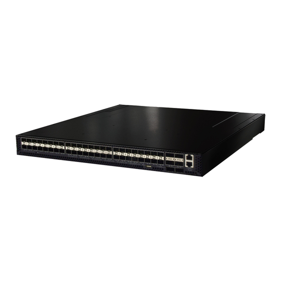
54-Port 10G/40G Fiber Ethernet Switch
AS5710-54X | AS5712-54X | AS5812-54X
1. Unpack the Switch and Check Contents
Rack Mounting Kit—2 front-post brackets, 2 rear-post
brackets, 20 screws, and 2 ear-locking screws
Power Cord (included with AC PSUs only)
Ground Wire (included with DC PSUs only)
Console Cable—RJ-45 to DB-9
DC Power Cable (included with 48 VDC PSU only)
Documentation—Quick Start Guide (this document)
and Safety and Regulatory Information
Note:
The switch has the Open Network Install
Environment (ONIE) software installer pre-loaded on the
switch, but no switch software image. Information about
compatible switch software can be found at
www.edge-core.com.
Caution:
The switch includes plug-in power supply (PSU)
and fan tray modules that are installed into its chassis. All
installed modules must have a matching airflow direction.
That is, if the installed power modules have a front-to-back
(F2B) airflow direction, all the installed fan tray modules
must also have a F2B airflow direction.
Note:
The switch drawings in this document are for
illustration only and may not match your particular switch
model.
2. Attach the Brackets
1
3
1
Attach each of the front- and rear-post brackets to the
switch using four of the included bracket screws.
2
Use an additional two screws to secure each of the rear-post
brackets at the mid-point on the sides of the switch.
www.edge-core.com
AS5710-54X,
AS5712-54X or
AS5812-54X
1
2
3
Use the screws and cage nuts supplied with the rack to
secure the switch in the rack.
Caution:
Installing the switch in a rack requires two
people. One person should position the switch in the rack,
while the other secures it using the rack screws.
装置の吸排気に必要な領域を マニ ュ アル上に規定 し て
い る 。
3. Adjust Rear-Post Bracket Ears
1
Lock the position of the rear-post bracket ears using the
included position-locking screws.
You can also adjust the rear-post bracket ears to fit different
rack depths from 56 cm to 75 cm.
4. Ground the Switch
1
2
1
Ensure the rack is properly grounded and in compliance
with ETSI ETS 300 253. Verify that there is a good electrical
connection to the grounding point on the rack (no paint or
isolating surface treatment).
2
Attach the grounding wire #14 AWG to the grounding point
on the switch rear panel. Then connect the other end of the
wire to rack ground. For details on grounding the switch
with a 12 VDC PSU in an Open Rack, refer to the Edgecore
ORSA-1U Open Rack Tray Set Installation Guide.
Caution:
The earth connection must not be removed
unless all supply connections have been disconnected.
– 1 –
1
E012018-AP-R07
150200001634A
Advertisement

Related Manuals for Edge-Core AS5710-54X


Summary of Contents for Edge-Core AS5710-54X
- Page 1 Quick Star t Guide 54-Port 10G/40G Fiber Ethernet Switch AS5710-54X | AS5712-54X | AS5812-54X Use the screws and cage nuts supplied with the rack to 1. Unpack the Switch and Check Contents secure the switch in the rack. AS5710-54X, Caution:...
- Page 2 Quick Start Guide Boot the switch. Wait for the ONIE software to locate and 5. Connect Power execute the NOS installer, and then wait for the installer to load the NOS software image. Subsequent switch boots will bypass ONIE and directly run the NOS software.
-
Page 3: Hardware Specifications
Hardware Specifications Switch Chassis Size (WxDxH) 438.4 x 473 x 43.4 mm (17.26 x 18.62 x 1.71 inches) Weight AS5710-54X / AS5712-54X: 8.87 kg (19.56 lb), with two installed PSUs AS5812-54X: 8.95 kg (19.73 lb), with two installed PSUs Temperature Operating: 0°... - Page 4 快 速 入 门 指 南 54 端口 10G/40G 乙太网路交换机 AS5710-54X | AS5712-54X | AS5812-54X 使用机架随附的螺丝和卡式螺母将交换机固定到支架 1. 打开交换机的包装并检查内装物 上。 警告:将此交换机安装在机架中时需要两个人。一个人 AS5710-54X, 将交换机放置在机架中,同时另一个人用机架螺丝将其 AS5712-54X 或 固定。 AS5812-54X 装置の吸排気に必要な領域を マニ ュ アル上に規定 し て い る 。 前柱支架 x2, 带可调节吊耳的后柱支架 x2, 支架螺丝...
- Page 5 快 速 入 门 指 南 启动交换机。等待 ONIE 软件找到和执行 NOS 安装程 5. 连接电源 序,然后等待安装程序加载 NOS 软件映像。 以后交换机启动时将跳过 ONIE 而直接运行 NOS 软件。 注意: 有关 ONIE 软件位置选项和设置的详细信息,请 参见 NOS 安装程序和 NOS 文档。 8. 连接网线 在交换机上安装 1 个或 2 个 AC 或 DC 电源模块。 本交换 机可使用最多...
- Page 6 438.4 x 473 x 43.4 mm (17.26 x 18.62 x 1.71 英 ( 宽 x 深 x 高 ) 寸 ) 重量 AS5710-54X / AS5712-54X: 8.87 kg (19.56 磅 ),含附带的两个 PSU AS5812-54X: 8.95 kg (19.73 磅 ),含附带的两个 PSU s 温度...
- Page 7 快速入門指南 54 埠 10G/40G 乙太網路交換機 AS5710-54X | AS5712-54X | AS5812-54X 使用隨機櫃提供的螺絲及籠罩螺帽,將交換器固定在機 1. 拆開交換器包裝並檢查內容物 櫃上。 AS5710-54X , 注意: 需要兩個人,將交換器裝到機櫃上。一人負責固 AS5712-54X 或 定交換器在機櫃上之位置,另一人負責用機櫃螺絲固 AS5812-54X 定。 装置の吸排気に必要な領域を マニ ュ アル上に規定 し て い る 。 前柱托架 x2、後柱托架附可調固定片 x2、托架螺 絲 x20、後托架固定片位置-定位螺絲 x2 3. 調整後柱托架固定片...
- Page 8 快速入門指南 啟動交換器。等待 ONIE 軟體找尋並執行 NOS 安裝程 5. 連接電源 式,並等待安裝程式載入 NOS 軟體映像檔。 之後交換器啟動時,會跳過 ONIE,直接運行 NOS 軟 體。 關於詳細軟體選項及 ONIE 設定說明,請參閱網 說明: 路作業系統 (NOS)安裝程式及 NOS 文件。 8. 連接網路線 在交換器上安裝 1 個或 2 個 AC 或 DC 電源模組 。 本交換 器可使用最多 2 個 PSU,且 PSU 的氣流方向必須與安裝 的風扇框相同。...
- Page 9 交換器機箱 438.4 x 473 x 43.4 mm (17.26 x 18.62 x 1.71 英 尺寸 (WxDxH) 吋) AS5710-54X / AS5712-54X: 重量 8.87 kg (19.56 lb),含兩個安裝之 PSU AS5812-54X: 8.95 kg (19.73 lb),含兩個安裝之 PSU 操作 : 0° C 至 40° C (32° F 至 104° F) 溫度...
Need help?
Do you have a question about the AS5710-54X and is the answer not in the manual?
Questions and answers