Table of Contents
Advertisement
Manual
EtherCAT®
LioN-X IO-Link Master:
0980 XSL 3912-121-007D-00F
(8 x IO-Link Class A, Multiprotocol)
LioN-Xlight IO-Link Master:
0980 LSL 3211-121-0006-004
(8 x IO-Link Class A, EtherCAT®)
0980 LSL 3210-121-0006-004
(4 x IO-Link Class A + 8 x DI, EtherCAT®)
Manual EtherCAT®
Technical Support
Version 1.1 04/2021
lumberg-automation-support.belden.com
Advertisement
Table of Contents

Related Manuals for Belden La 0980 XSL 3912-121-007D-00F


Summary of Contents for Belden La 0980 XSL 3912-121-007D-00F
- Page 1 (8 x IO-Link Class A, Multiprotocol) LioN-Xlight IO-Link Master: 0980 LSL 3211-121-0006-004 (8 x IO-Link Class A, EtherCAT®) 0980 LSL 3210-121-0006-004 (4 x IO-Link Class A + 8 x DI, EtherCAT®) Manual EtherCAT® Technical Support Version 1.1 04/2021 lumberg-automation-support.belden.com...
-
Page 2: Table Of Contents
Contents Contents 1 About this manual 1.1 General information 1.2 Explanation of symbols 1.2.1 Use of danger information 1.2.2 Use of general information ® 1.2.3 EtherCAT trademark information 1.3 Version information 2 Safety instructions 2.1 Intended use 2.2 Qualified personnel 3 Designations and synonyms 4 System description 4.1 About LioN-X and LioN-Xlight... - Page 3 Contents 5.5 Other features 6 Assembly and wiring 6.1 General information 6.2 Outer dimensions 6.2.1 LioN-X multiprotocol variants ® 6.2.2 LioN-Xlight variants with EtherCAT 6.2.3 Notifications 6.3 Port assignments 6.3.1 Ethernet ports, M12 socket, 4-pin, D-coded 6.3.2 Power supply with M12 power L-coded 6.3.3 I/O ports as M12 sockets 6.3.3.1 IO-Link Class A 7 Starting operation...
- Page 4 Contents 8.2.6 Digital I/O mode, Channel B 8.2.7 Digital Input logic 8.2.8 Digital Input filter 8.2.9 Digital Output restart 8.2.10 Additional IO-Link port settings 8.2.11 IO-Link Parameterization 8.2.12 IO-Link configuration data 8.2.13 IO-Link serial number 8.2.14 IO-Link information data 8.2.15 IO-Link serial number of connected devices ®...
- Page 5 Contents 10 IIoT functionality 10.1 MQTT 10.1.1 MQTT configuration 10.1.2 MQTT topics 10.1.2.1 Base topic 10.1.2.2 Publish topic 10.1.3 MQTT configuration - Quick start guide 10.1.3.1 MQTT configuration via JSON 10.2 OPC UA 10.2.1 OPC UA configuration 10.2.2 OPC UA address space 10.2.3 OPC UA configuration - Quick start guide 10.2.3.1 OPC UA configuration via JSON 10.3 REST API...
- Page 6 Contents 12 Firmware update 12.1 Firmware update via FoE 13 Technical data 13.1 General ® 13.2 EtherCAT protocol 13.3 Power supply of the module electronics/sensors 13.4 Power supply of the actuators 13.5 IO-Link Master ports Class A, Pin 4 13.5.1 Configured as a digital input 13.5.2 Configured as a digital output 13.5.3 Configured as an IO-Link port in COM mode 13.6 IO-Link Master ports Class A, Pin 2...
-
Page 7: About This Manual
– Lumberg Automation™ – Im Gewerbepark 2 D-58579 Schalksmühle Germany lumberg-automation-support.belden.com www.lumberg-automation.com catalog.belden.com Belden Deutschland GmbH – Lumberg Automation™ – reserves the right to make technical changes or changes to this manual at any time without notice. Manual EtherCAT® Version 1.1 04/2021... -
Page 8: Explanation Of Symbols
1.2 Explanation of symbols 1 About this manual 1.2 Explanation of symbols 1.2.1 Use of danger information Danger information is denoted as follows: Danger: Means that death, serious physical injury or substantial damage to property will occur if the required safety measures are not taken. -
Page 9: Ethercat ® Trademark Information
1 About this manual 1.3 Version information 1.2.3 EtherCAT ® trademark information EtherCAT ® is a registered trademark and patented technology, licensed by Beckhoff Automation GmbH, Germany. 1.3 Version information Index Created Changed Version number Version 1.0 Version 1.1 Date 03/2021 04/2021 Table 1: Overview of manual revisions... -
Page 10: Safety Instructions
2.1 Intended use 2 Safety instructions 2 Safety instructions 2.1 Intended use The products described in this manual are decentralized IO-Link Masters on an Industrial Ethernet Network. We adhere to all safety standards when developing, producing, testing, and documenting our products. When you adhere to the handling specifications and safety instructions described for the configuration, assembly, and correct operation, there should not normally be any risks for people or equipment. -
Page 11: Qualified Personnel
Only Belden Deutschland GmbH – Lumberg Automation™ – is permitted to make changes to the hardware or software of the products that go beyond the scope of this manual. -
Page 12: Designations And Synonyms
3 Designations and synonyms 3 Designations and synonyms Application Programming Interface Bus Fault LED Big Endian Data format with High-B on first place (PROFINET and IO-Link) Back-Up Inconsistency (EIP diagnostics) I/O port pin 4 mode, IO-Link communication/switching signal Ch. A Channel A (Pin 4) of I/O port Ch. - Page 13 3 Designations and synonyms GSDML General Station Description Markup Language High-B High-Byte IO-Link port COM Error (EIP diagnostics) Invalid Cycle Time (EIP diagnostics) IO-Link port Device Error (EIP diagnostics) IO-Link port Device Notification (EIP diagnostics) IO-Link port Device Warning (EIP diagnostics) IIoT Industrial Internet of Things Input process data Length Error (EIP diagnostics)
- Page 14 3 Designations and synonyms MQTT Message Queuing Telemetry Transport (open networking protocol) Most Significant Bit Metric thread according to DIN 13-1 with 12 mm diameter Output process data Length Error (EIP diagnostics) OPC UA Open Platform Communications Unified Architecture (platform independent, service-oriented architecture) Programmable Logic Controller PROFINET...
-
Page 15: System Description
Use all benefits of the Lumberg Automation product solution by additionally ™ downloading the configuration tool LioN-Management Suite V2.0 from www.belden.com to enable e.g. a fast and easy parameterization of the connected IO-Link devices via the embedded IODD interpreter. Manual EtherCAT®... -
Page 16: Device Variants
4.2 Device variants 4 System description 4.2 Device variants The following IO-Link Masters are available in the LioN-X and the LioN-Xlight family: Article Product designation Description I/O port functionality number 935700001 0980 XSL 3912-121-007D-00F LioN-X M12-60 mm, 8 x IO-Link Class A IO-Link Master Multiprotocol Security... - Page 17 4 System description 4.2 Device variants Article Product designation Description I/O port functionality number 935702003 0980 LSL 3210-121-0006-004 LioN-Xlight M12-60 mm, 4 x IO-Link Class A IO-Link Master + 8 x DI EtherCAT ® Table 3: Overview of LioN-X and LioN-Xlight variants Manual EtherCAT®...
-
Page 18: I/O Port Overview
4.3 I/O port overview 4 System description 4.3 I/O port overview The following tables show the main I/O port differences of the LioN-X IO-Link Master family. Pin 4 and Pin 2 of the I/O ports can be configured partly to IO-Link, Digital Input or Digital Output. LioN-X Device Port... - Page 19 4 System description 4.3 I/O port overview LioN-Xlight Device Port Pin 1 U Pin 4 / Ch. A (C/Q) Pin 2 / Ch. variant: B (I/Q) Info: Class A Type 1 Type 1 – Supply by U Out (2 A) DO (0.5 A) Out (2 A) DO (0.5 A)
- Page 20 4.3 I/O port overview 4 System description Device Port Pin 1 U Pin 4 / Ch. A (C/Q) Pin 2 / Ch. variant: B (I/Q) Info: Class A Type 1 Type 1 – Supply by U Out (0.7 A) – –...
-
Page 21: Overview Of Product Features
5 Overview of product features 5.1 EtherCAT product features ® 5 Overview of product features 5.1 EtherCAT product features ® Data connection The connection option provided by LioN-X is the widely- used M12 connector with D-coding for the EtherCAT ® network. -
Page 22: I/O Port Features
5.2 I/O port features 5 Overview of product features 5.2 I/O port features IO-Link specification. LioN-X is ready for IO-Link specification v1.1.3. 8 x IO-Link Master ports Depending on the variant, the Master device has 4 Class A or 8 Class A ports with an additional hard- wired digital input on pin 2 of the I/O port. -
Page 23: Integrated Web Server
5 Overview of product features 5.3 Integrated Web server meanings of the LED colors, please see section LEDs on page 147. 5.3 Integrated Web server Network parameter display Get an overview of network parameters such as the IP address, subnet mask and gateway. Displaying diagnostics View diagnostics via the integrated Web server. -
Page 24: Security Features
5.4 Security features 5 Overview of product features 5.4 Security features Firmware signature official firmware update packages contain a signature which prevents the system against manipulated firmware updates. User manager The Web server provides a user manager to protect the Web interface against unauthorized access. You can manage the allowed users with the different access levels “Admin”... -
Page 25: Other Features
5 Overview of product features 5.5 Other features 5.5 Other features Interface protection The modules have reverse polarity, short-circuit and overload protection for all interfaces. For more details, see section Port assignments on page Failsafe The modules support a failsafe function. This allows you to define the behavior of every single channel configured as an output in the case of a loss of the PLC communication. -
Page 26: Assembly And Wiring
6.1 General information 6 Assembly and wiring 6 Assembly and wiring 6.1 General information Mount the module on a flat surface using 2 screws (M4x 25/30). The torque required here is 1 Nm. Use washers for all fastening methods as per DIN 125. Attention: The modules have a ground connection with an M4 thread for the conduction of interference currents and the EMC immunity. -
Page 27: Outer Dimensions
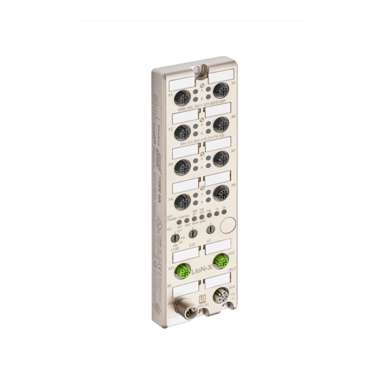
6 Assembly and wiring 6.2 Outer dimensions 6.2 Outer dimensions 6.2.1 LioN-X multiprotocol variants Figure 1: 0980 XSL 3912-121-007D-00F Manual EtherCAT® Version 1.1 04/2021... -
Page 28: Lion-Xlight Variants With Ethercat
6.2 Outer dimensions 6 Assembly and wiring 6.2.2 LioN-Xlight variants with EtherCAT ® Figure 2: 0980 LSL 3211-121-0006-004 Manual EtherCAT® Version 1.1 04/2021... - Page 29 6 Assembly and wiring 6.2 Outer dimensions Figure 3: 0980 LSL 3210-121-0006-004 Manual EtherCAT® Version 1.1 04/2021...
-
Page 30: Notifications
6.3 Port assignments 6 Assembly and wiring 6.2.3 Notifications Attention: For UL application: Be sure to use a UL-certified cable with a suitable evaluation to connect the devices (CYJV or PVVA). To program the control, please refer to the OEM information, and only use suitable accessories. Only approved for interior use. -
Page 31: Power Supply With M12 Power L-Coded
6 Assembly and wiring 6.3 Port assignments Port Signal Function Ethernet Transmit data plus Ports X01, X02 Receive data plus Transmit data minus Receive data minus Table 7: Assignment of ports X01, X02 Caution: Risk of destruction! Never connect the power supply to the data cables. -
Page 32: I/O Ports As M12 Sockets
6.3 Port assignments 6 Assembly and wiring Power supply Signal Function (+24 V) Sensor/system power supply GND_U Ground/reference potential U GND_U Ground/reference potential U (+24 V) Load supply (NOT electrically isolated to U internally in device) FE (PE) Functional ground Table 8: Power supply with M12-Power Attention: Only use power supply units for the system/sensor and actuator supply that correspond to PELV (Protective Extra... - Page 33 6 Assembly and wiring 6.3 Port assignments Signal Function 0980 XSL 3x12-121... IO-Link Class A, ports +24 V power supply +24 V X1 - X8 IN/OUT Ch. B: Digital inputs or digital outputs Ground/reference potential C/Q IN/OUT Ch. A: IO-Link data communication, digital input or digital output n.c.
-
Page 34: Starting Operation
Xlight devices. All device variants are grouped in a single ESI file. The file can be downloaded from the product pages on our online catalog: catalog.belden.com On request, the ESI file is also sent by the support team. The file for the LioN-X EtherCAT devices is named: ®... -
Page 35: Mac Addresses
7 Starting operation 7.2 MAC addresses 7.2 MAC addresses Every device has three unique MAC address assigned by the manufacturer that cannot be changed by the user. The first assigned MAC address is printed onto the device. For EtherCAT , the MAC address has no function. For EoE (Ethernet over ®... -
Page 36: Setting The Rotary Encoding Switches
7.3 Setting the rotary encoding 7 Starting operation switches 7.3 Setting the rotary encoding switches Attention: Only applicable for LioN-X multiprotocol variants; not applicable for LioN-Xlight variants. The LioN-X multiprotocol variants allow you to select different protocols for communication within an industrial Ethernet system. In this way the IO-Link Masters with multiprotocol function can be integrated into different networks without it being necessary to purchase products specific for each protocol. - Page 37 7 Starting operation 7.3 Setting the rotary encoding switches With the other rotary encoding switches (x10 / x1), you set the last two digits of the IP address when you are using EtherNet/IP or Modbus TCP. Protocol x100 EtherNet/IP PROFINET –...
-
Page 38: Factory Reset
7.3 Setting the rotary encoding 7 Starting operation switches 7.3.1 Factory reset A factory reset restores the original factory settings and thus resets the changes and settings you have made up to that point. It also resets the protocol selection. To perform a factory reset, set the first rotary encoding switch (x100) to 9, the second (x10) to 7, and the third (x1) also to 9. -
Page 39: Configuration And Operation In Twincat
8 Configuration and operation in 8.1 PDO assignments TwinCAT ® 8 Configuration and operation in TwinCAT ® 8.1 PDO assignments The LioN-X and LioN-Xlight devices support different PDO (Process Data Object) assignments for input and output data. By selecting the relevant PDO, you can decide your preferred I/O data content. - Page 40 8.1 PDO assignments 8 Configuration and operation in TwinCAT ® PDO 0x1A01 PDO content Index Size Index Size Type Name 0x1A01 0x6010:1 UINT32 1st byte of IO- Link input data … … … … 0x6010:32 UINT32 32nd byte of IO-Link input data PDO 0x1A02 PDO content...
- Page 41 8 Configuration and operation in 8.1 PDO assignments TwinCAT ® PDO 0x1A04 PDO content Index Size Index Size Type Name 0x1A04 0x6040:1 UINT32 1st byte of IO- Link input data … … … … 0x6040:32 UINT32 32nd byte of IO-Link input data PDO 0x1A05 PDO content...
- Page 42 8.1 PDO assignments 8 Configuration and operation in TwinCAT ® PDO 0x1A07 PDO content Index Size Index Size Type Name 0x1A07 0x6070:1 UINT32 1st byte of IO- Link input data … … … … 0x6070:32 UINT32 32nd byte of IO-Link input data PDO 0x1A08 PDO content...
- Page 43 8 Configuration and operation in 8.1 PDO assignments TwinCAT ® PDO 0x1A09 PDO content Index Size Index Size Type Name 0x1A09 0x10F3: 4 UINT32 Flag “New Messages Available” from Diagnostic Object 0x10F3 PDO 0x1A0A PDO content Index Size Index Size Type Name 0x1A0A...
- Page 44 8.1 PDO assignments 8 Configuration and operation in TwinCAT ® PDO 0x1A80 PDO content Index Size Index Size Type Name 0x1A80 0xF100:1 UINT32 Status IO-Link port 1 0xF100:2 UINT32 Status IO-Link port 2 0xF100:3 UINT32 Status IO-Link port 3 0xF100:4 UINT32 Status IO-Link port 4...
-
Page 45: Output Data
8 Configuration and operation in 8.1 PDO assignments TwinCAT ® 8.1.2 Output data PDO 0x1600 PDO content Index Size Index Size Type Name 0x1A00 0x7000:1 UINT32 1st byte of IO- Link output data … … … … 0x7000:32 UINT32 32nd byte of IO-Link output data PDO 0x1601... - Page 46 8.1 PDO assignments 8 Configuration and operation in TwinCAT ® PDO 0x1602 PDO content Index Size Index Size Type Name 0x1A02 0x7020:1 UINT32 1st byte of IO- Link output data … … … … 0x7020:32 UINT32 32nd byte of IO-Link output data PDO 0x1603 PDO content...
- Page 47 8 Configuration and operation in 8.1 PDO assignments TwinCAT ® PDO 0x1605 PDO content Index Size Index Size Type Name 0x1605 0x7050:1 UINT32 1st byte of IO- Link output data … … … … 0x7050:32 UINT32 32nd byte of IO-Link output data PDO 0x1606 PDO content...
- Page 48 8.1 PDO assignments 8 Configuration and operation in TwinCAT ® PDO 0x1608 PDO content Index Size Index Size Type Name 0x1608 0x2280:1 UINT32 Digital output mapping for ports X1 - X4 Bitwise 0x2280:2 UINTtwincat32 Digital output mapping for ports X5 – X8 Bitwise 0x2280:3 UINT32...
- Page 49 8 Configuration and operation in 8.1 PDO assignments TwinCAT ® 8.1.3 Modular slots The ESI file features a modular slot-based PDO configuration for different IO- Link configurations. The following slots are available: Slot name Description STD_IN_1_bit IO-Link port as standard Digital Input IOL_I_1byte IO-Link, 1 byte of process data input IOL_I_2byte...
- Page 50 8.1 PDO assignments 8 Configuration and operation in TwinCAT ® Slot name Description IOL_I/O_2/2byte IO-Link, 2 bytes of process data input 2 bytes of process data output IOL_I/O_2/4byte IO-Link, 2 bytes of process data input 4 bytes of process data output IOL_I/O_4/4byte IO-Link, 4 bytes of process data input...
- Page 51 8 Configuration and operation in 8.1 PDO assignments TwinCAT ® Slot name Description IOL_I/O_16/16byte IO-Link, 16 bytes of process data input 16 bytes of process data output IOL_I/O_24/24byte IO-Link, 24 bytes of process data input 24 bytes of process data output IOL_I/O_32/32byte IO-Link, 32 bytes of process data input...
- Page 52 8.2 Device parameters 8 Configuration and operation in TwinCAT ® 8.2 Device parameters The LioN-X and LioN-Xlight devices support different parameters. The parameters must be transferred from the controller to the device during startup. The following blocks of parameters can be adjusted. 8.2.1 Extended parameters The following table represents extended parameters of the IO-Link ports.
- Page 53 8 Configuration and operation in 8.2 Device parameters TwinCAT ® 8.2.2 Failsafe replacement values The firmware of the devices provides a fail-safe function for the port while in IO-Link mode. During device configuration, you have the option to define the replacement value of the IO-Link output data.
- Page 54 8.2 Device parameters 8 Configuration and operation in TwinCAT ® 8.2.3 Failsafe mode for the digital output The firmware of the devices provides a fail-safe function for ports in digital output mode. During device configuration, you have the option to define the status of channels A and B for ports in digital output mode in the case of an interruption or the loss of communication.
- Page 55 8 Configuration and operation in 8.2 Device parameters TwinCAT ® SDO content 0x2380 : 4 UINT8 Port 2 Channel B 0 = Set Low 1 = Set High 2 = Hold Last Others: reserved 0x2380 : 5 UINT8 Port 3 Channel A 0 = Set Low 1 = Set High 2 = Hold Last...
- Page 56 8.2 Device parameters 8 Configuration and operation in TwinCAT ® SDO content 0x2380 : 11 UINT8 Port 6 Channel A 0 = Set Low 1 = Set High 2 = Hold Last Others: reserved 0x2380 : 12 UINT8 Port 6 Channel B 0 = Set Low 1 = Set High 2 = Hold Last...
- Page 57 8 Configuration and operation in 8.2 Device parameters TwinCAT ® 8.2.4 General device settings The device supports the setting of different parameters. The following blocks of parameters can be adjusted: SDO content Index Size Index Size Type Name 0x2381 0x2381: 1 BOOL Web Interface Locked 0 = false, 1 = true...
- Page 58 8.2 Device parameters 8 Configuration and operation in TwinCAT ® 8.2.5 Surveillance timeout The firmware of the devices allows you to define a delay time before the automatic monitoring of the output currents. This is known as the surveillance timeout. You can define the surveillance timeout for every individual output channel.
- Page 59 8 Configuration and operation in 8.2 Device parameters TwinCAT ® SDO content 0x2382: 9 UINT8 Surveillance Timeout Port 5 Channel 0x2382: UINT8 Surveillance Timeout Port 5 Channel 0x2382: UINT8 Surveillance TimeoutPort 6 Channel 0x2382: UINT8 Surveillance Timeout Port 6 Channel 0x2382: UINT8 Surveillance Timeout Port 7 Channel...
- Page 60 8.2 Device parameters 8 Configuration and operation in TwinCAT ® 8.2.6 Digital I/O mode, Channel B The device supports the configuration of channel B (Pin 2) of the IO-Link port via SDO 0x2383 in input or output mode. SDO content Index Size Index...
- Page 61 8 Configuration and operation in 8.2 Device parameters TwinCAT ® SDO content 0x2383: 8 UINT8 Digital I/O Mode, Port 8 Channel B 1 = Input 2 = Output Others = reserved Manual EtherCAT® Version 1.1 04/2021...
- Page 62 8.2 Device parameters 8 Configuration and operation in TwinCAT ® 8.2.7 Digital Input logic The device supports the configuration of digital input logic for Channel A (Pin 4) and Channel B (Pin 2) of the IO-Link port. The following values are only applicable for ports in digital input mode. SDO content Index Size...
- Page 63 8 Configuration and operation in 8.2 Device parameters TwinCAT ® SDO content 0x2384: 8 UINT8 Digital Input logic Port 4 Channel 0: NO 1: NC Digital Input logic Port 5 Channel 0x2384: 9 UINT8 0: NO 1: NC 0x2384: UINT8 Digital Input logic Port 5 Channel 0: NO 1: NC...
- Page 64 8.2 Device parameters 8 Configuration and operation in TwinCAT ® 8.2.8 Digital Input filter The device supports the configuration of a digital input filter for Channel A (Pin 4) and Channel B (Pin 2) of the IO-Link port. The following values are only applicable for ports in digital input mode. SDO content Index Size...
- Page 65 8 Configuration and operation in 8.2 Device parameters TwinCAT ® 8.2.9 Digital Output restart The device supports the configuration of a digital output timeout before restart for Channel A (Pin 4) and Channel B (Pin 2) of the IO-Link port. The following values are only applicable for ports in digital output mode.
- Page 66 8.2 Device parameters 8 Configuration and operation in TwinCAT ® SDO content 0x2386: 12 BOOL Digital output timeout before restart in ms Port 6 Channel B 0x2386: 13 BOOL Digital output timeout before restart in ms Port 7 Channel A 0x2386: 14 BOOL Digital output timeout before restart in ms Port 7...
- Page 67 8 Configuration and operation in 8.2 Device parameters TwinCAT ® 8.2.10 Additional IO-Link port settings The device firmware provides the following additional setting options for each individual IO-Link port via SDO. SDO content Index Size Index Size Type Name 0x30n0 0x30n0:1 UINT8 Swap Mode...
- Page 68 8.2 Device parameters 8 Configuration and operation in TwinCAT ® Swap Length The swapping can be setup to Word (2 Bytes) or DWord (4 Bytes) → Word Swapping: Byte 1 - Byte 2 => Byte 2 - Byte 1 → DWord Swapping: Byte 1 - Byte 4 => Byte 4 – Byte 1 Swapping Offset A swapping offset in bytes can be setup in dependency of the configured I/O-Data length.
- Page 69 8 Configuration and operation in 8.2 Device parameters TwinCAT ® 8.2.11 IO-Link Parameterization The device features read or write of ISDU (IO-Link Service Data) parameters via SDO 0x40n0. SDO content Index Size Index Size Type Name Control 0x40n0 0x40n0:1 UINT8 0x00: no action 0x02: write 0x03: read...
- Page 70 8.2 Device parameters 8 Configuration and operation in TwinCAT ® 8.2.12 IO-Link configuration data This is the standard 0x80n0 object for the IO-Link configuration data as per the IO-Link device profile. SDO content Index Size Index Size Type Name 0x80n0 0x80n0:4 UINT32 Device ID 0x80n0:5...
- Page 71 8 Configuration and operation in 8.2 Device parameters TwinCAT ® SDO content 0x80n0:38 UINT16 Compatible ID 0x80n0:39 UINT16 Reserved UINT16 Master Control 0x80n0:40 Control of the IO-Link master port. Defines the different operating modes of the IO-Link master. Bits 0...3: 0: Inactive 1: Digital Input Port 2: Digital Output Port...
- Page 72 8.2 Device parameters 8 Configuration and operation in TwinCAT ® 8.2.14 IO-Link information data This is standard 0x90n0 object for the IO-Link information data as per the IO- Link device profile. SDO content Index Size Index Size Type Name 0x90n0 7 0x90n0:4 UINT32 Device ID 0x90n0:5...
- Page 73 8 Configuration and operation in 8.2 Device parameters TwinCAT ® SDO content 0x90n0:37 UINT8 Process data OUT length Number and structure of input data This value is transmitted in IO-Link format as "ProcessDataOut" according to version 1.0 of the IO-Link specification. Bit 0...4: Length Bit 5: reserved Bit 6: SIO Indicator (if device supports standard I/...
- Page 74 8.3 Configuration example with 8 Configuration and operation in TwinCAT TwinCAT ® ® 8.3 Configuration example with TwinCAT ® 3 The configuration and start-up of the devices described below refer to the TwinCAT 3 software by Beckhoff Automation GmbH & Co. KG. If you use the ®...
- Page 75 8 Configuration and operation in 8.3 Configuration example with TwinCAT TwinCAT ® ® 5. If not already done, choose the network adapter and install the driver for EtherCAT real time communication. ® Browse to Adapter in the right workspace window and click on Compatible Devices...
- Page 76 8.3 Configuration example with 8 Configuration and operation in TwinCAT TwinCAT ® ® 8.3.1 Configuration of 0980 XSL 391x-1x1 devices 1. Selecting the I/O device from the hardware catalog: Browse to Solution Explorer > I/O > Devices in the left workspace window. Right-click on Device 1 (EtherCAT) and choose the option Add New Item ….
- Page 77 8 Configuration and operation in 8.3 Configuration example with TwinCAT TwinCAT ® ® 3. Configure the Process Data: Browse to Process Data in the right workspace window and choose the PDOs for Inputs and Outputs. Manual EtherCAT® Version 1.1 04/2021...
- Page 78 8.3 Configuration example with 8 Configuration and operation in TwinCAT TwinCAT ® ® 8.3.2 EoE IP address 1. Set the IP address for the EoE (Ethernet over EtherCAT ® ) protocol: For using the Web interface of the device, the IP address must be set. Click on EtherCAT >...
- Page 79 8 Configuration and operation in 8.3 Configuration example with TwinCAT TwinCAT ® ® 3. Activate IP Port and IP Address when using Web services. Enter your IP settings depending from your local network adapter settings. Manual EtherCAT® Version 1.1 04/2021...
- Page 80 8.3 Configuration example with 8 Configuration and operation in TwinCAT TwinCAT ® ® 8.3.3 Activate configuration Warning: Risk of personal injury or damage of the equipment. Keep away from moveable machine parts during setting up the inputs or outputs of the device. network, click on TwinCAT in When the device is connected to the EtherCAT ®...
- Page 81 9 Diagnostics processing 9.1 Error of the system/sensor power supply 9 Diagnostics processing 9.1 Error of the system/sensor power supply The voltage value for the incoming system/sensor power supply is also monitored globally. If the voltage drops below approx. 18 V, or exceeds approx.
- Page 82 9.4 Overload/short circuit of the digital 9 Diagnostics processing outputs 9.4 Overload/short circuit of the digital outputs A channel error is determined by comparing the target value set by a controller and the actual value of an output channel. When an output channel is activated (rising edge of the channel state), the channel errors are filtered for the period that you set using the "Surveillance- Timeout"...
- Page 83 9 Diagnostics processing 9.6 Diagnostic history object (0x10F3) 9.6 Diagnostic history object (0x10F3) SDO content Index Size Index Size Type Name 0x10F3 0x10F3: 1 UINT8 Maximum Messages 0x10F3: 2 UINT8 Newest Message 0x10F3: 3 UINT8 Newest Acknowledged Message 0x10F3: 4 BOOL New Messages Available 0x10F3: 5...
- Page 84 9.6 Diagnostic history object (0x10F3) 9 Diagnostics processing Writing = 6...69: SI3 = written value (without checking) All messages up to the age of the message which is in the written sub- index are acknowledged. The slave does not check if those messages have been read before.
- Page 85 9 Diagnostics processing 9.6 Diagnostic history object (0x10F3) code 0x06090030 (value range of parameter exceeded) in the following case: SI3 is written with a value of a sub-index which does not hold a message. Writing = 69...255: The slave returns SDO abort with code 0x06090031 (value of parameter written too high).
- Page 86 9.6 Diagnostic history object (0x10F3) 9 Diagnostics processing 0: Warning messages are stored in the diagnosis message queue (default). 1: Warning messages will not be stored in the diagnosis message queue. Bit 3: Disable error messages 0: Error messages are stored in the diagnosis message queue (default).
- Page 87 9 Diagnostics processing 9.7 Diagnostic data object (0xA0n0) 9.7 Diagnostic data object (0xA0n0) SDO content Index Size Index Size Type Name 0xA0n0 0xA0n0: 1 UINT8 IO-Link State 0xA0n0: 2 UINT8 Lost Frames IO-Link State State of the IO-Link Master (state machine of the IO-Link port) 0x0 = Port inactive 0x01 = Digital input 0x02 = Digital output...
- Page 88 9.8 Device status object (0xF100) 9 Diagnostics processing 9.8 Device status object (0xF100) SDO content Index Size Index Size Type Name 0xF100 0xF100: 1 UINT8 Status Port 1 0xF100: 2 UINT8 Status Port 2 0xF100: 3 UINT8 Status Port 3 0xF100: 4 UINT8 Status Port 4...
- Page 89 9 Diagnostics processing 9.9 Emergency messages 9.9 Emergency messages If set in the parameters, the Device sends emergency messages to the Master in case of a detected diagnosis on the Device. Emergency Error description error code 0x0000 No error 0x2300 –...
- Page 90 10 IIoT functionality 10 IIoT functionality The Lion-X variants offer a number of new interfaces and functions for the optimal integration into existing or future IIoT (Industrial Internet of Things) networks. The devices continue to work as field bus devices which communicate with and are controlled by a PLC (Programmable Logic Controller).
- Page 91 10 IIoT functionality 10.1 MQTT 10.1 MQTT MQTT functions are only applicable for the following device variant: 0980 XSL 3912-121-007D-00F The MQTT (Message Queuing Telemetry Transport) protocol is an open network protocol for machine-to-machine communication, which provides the transmission of telemetric data messages between devices. The integrated MQTT client allows the device to publish a specific set of information to an MQTT broker.
- Page 92 10.1 MQTT 10 IIoT functionality The following configuration elements are available: Element Data Description Example data type mqtt-enable boolean Master switch for the MQTT client. true / false broker string IP address of the MQTT Broker "192.168.1.201" login string Username for MQTT Broker "admin"...
- Page 93 10 IIoT functionality 10.1 MQTT Element Data Description Example data type number Selects the "Quality of Service" status 0 = At most once. for all published messages. 1 = At least once 2 = Exactly once Table 11: MQTT configuration MQTT response: The resulting response is a JSON object with a "status"...
- Page 94 10.1 MQTT 10 IIoT functionality 10.1.2 MQTT topics MQTT mainly relates to topics. All messages are attached to a topic which adds context to the message itself. Topics may consist of any string and they are allowed to contain slashes (/) as well as wildcard symbols (*, #). 10.1.2.1 Base topic For LioN-X and the LioN-Xlight variants there is a configurable Base topic which is the prefix for all topics.
- Page 95 10 IIoT functionality 10.1 MQTT There are the following domains: Domain name Definition Example content identity All fixed data which is defined by the Device name, ordering number, MAC used hardware and which cannot be address, port types, port capabilites changed by configuration or at runtime.
- Page 96 10.1 MQTT 10 IIoT functionality Topic Content examples Total Publish publish interval count [base-topic]/identity/ Name, ordering number, MAC, vendor, I&M Startup gateway etc. [base-topic]/identity/ Port name, port type Startup port/n [base-topic]/config/ Configuration parameters, ip address etc. Interval gateway [base-topic]/config/port/ Port mode, data storage, mapping, direction Interval [base-topic]/status/ Bus state, device diagnosis, master events...
- Page 97 10 IIoT functionality 10.1 MQTT 10.1.2.2 Publish topic Overview of all publish JSON data for the defined topics: Data type json_string ordering_number json_string device_type json_string serial_number json_string mac_address json_string production_date json_string fw_name json_string fw_date json_string fw_version json_string hw_version json_string vendor_name json_string vendor_address json_string...
- Page 98 10.1 MQTT 10 IIoT functionality Data type Range Default value Remarks fieldbus_protocol json_string profinet, ethernet/ip, ethercat PNS: network_configuration json_string EIS: stored_value, bootp, dhcp rotary_switches json_integer 0..999 ip_address json_string 192.168.1.1 subnet_mask json_string 255.255.255.0 report_alarms json_boolean 0.0.0.0 report_ul_alarm json_boolean true / false true report_do_fault_without_ul json_boolean...
- Page 99 10 IIoT functionality 10.1 MQTT Data type Range Default value Remarks protocol json_string wait_for_io_system wait_for_io_Connection failsafe connected error ethernet_port1 json_string 100_mbit/s_full 100_mbit/s 10_mbit/s_full 100_mbit/s ethernet_port2 json_string 100_mbit/s_full 100_mbit/s 10_mbit/s_full 100_mbit/s module_restarts json_integer 0..4294967295 channel_diagnosis json_boolean true / false failsafe_active json_boolean true / false system_voltage_fault json_boolean...
- Page 100 10.1 MQTT 10 IIoT functionality Data type Range Default value Remarks port json_integer 1..8 type json_string digital_universal digital_input digital_Output io_link max_output_power_cha json_string 2.0_mA 0.5_mA max_output_power_chb json_string 2.0_mA 0.5_mA channel_cha json_string input/output input output io_link channel_chb json_string input/output input output io_link Table 20: Identity/port/1 ...
- Page 101 10 IIoT functionality 10.1 MQTT Data type Range Default value Remarks port json_integer 1..8 direction_cha json_string input/output input output direction_chb json_string input/output input output failsafe_cha json_string set_low set_low set_high hold_last failsafe_chb json_string set_low set_low set_high hold_last surveillance_timeout_cha json_integer 0..255 surveillance_timeout_chb json_integer 0..255 Table 21: Config/port/1 ...
- Page 102 10.1 MQTT 10 IIoT functionality 10.1.3 MQTT configuration - Quick start guide Attention: Lumberg Automation is not responsible for any content of the referenced Web pages and provides no warranty for any functionality of the named third party software. 10.1.3.1 MQTT configuration via JSON 1.
- Page 103 10 IIoT functionality 10.1 MQTT 3. Read MQTT: GET: [IP-address]/r/config/mqtt.json Manual EtherCAT® Version 1.1 04/2021...
- Page 104 OPC UA client can connect for information exchange secure in transmission. For OPC UA, we comply (apart from the exceptions listed below) with the IO-Link Companion Specification, which can be downloaded from catalog.belden.com or directly from io-link.com. Manual EtherCAT® Version 1.1 04/2021...
- Page 105 10 IIoT functionality 10.2 OPC UA Feature Support Managing IODDs Not supported (chapter 6.1.6 in the specification) Mapping IODD information to OPC UA ObjectTypes Not supported (chapter 6.3 in the specification) IOLinkIODDDeviceType Not supported (chapters 7.2 ff. in the specification) ObjectTypes generated based on IODDs Not supported (chapters 7.3 ff.
- Page 106 10.2 OPC UA 10 IIoT functionality There are the following configuration elements: Element Data Description Example data type port integer Server port for the OPC UA server. 0, 4840, 0xFFFF opcua-enable boolean Master switch for the OPC UA server. true / false anon-allowed boolean If true, anonymous login is allowed.
- Page 107 10 IIoT functionality 10.2 OPC UA {"status": 0} {"status": "error": [{"Element": "root", "Message": "Not JSON object"}]} 10.2.2 OPC UA address space OPC UA provides different services on the LioN-X devices with which a client can navigate through the hierarchy of the address space and read or write variables.
- Page 108 10.2 OPC UA 10 IIoT functionality 10.2.3 OPC UA configuration - Quick start guide Attention: Lumberg Automation is not responsible for any content of the referenced Web pages and provides no warranty for any functionality of the named third party software. 10.2.3.1 OPC UA configuration via JSON 1.
- Page 109 10 IIoT functionality 10.2 OPC UA 3. Read OPC UA: GET: [IP-address]/r/config/opcua.json Manual EtherCAT® Version 1.1 04/2021...
- Page 110 1. A standardized REST API that has been specified by the IO-Link Community and is described separately: JSON_Integration_10222_V100_Mar20.pdf Please download the file from catalog.belden.com or directly from link.com. Attention: Consider the following table to get an overview of the supported features of the IO-Link specification:...
- Page 111 10 IIoT functionality 10.3 REST API Feature Supported Port GET /ports GET /capabilities GET /status GET /configuration POST /configuration GET /datastorage Not supported POST /datastorage Not supported Devices GET /devices GET /capabilities GET /identification POST /identification GET /processdata/value GET /processdata/getdata/value GET /processdata/setdata/value POST /processdata/value GET /parameters...
- Page 112 Not supported GET /iodds/file Not supported Table 25: Support of REST API features according to the IO-Link specification 2. A customized Belden REST API that is described in the following chapters. 10.3.1 Standard device information Request method: http GET Request URL: <ip>/info.json...
- Page 113 10 IIoT functionality 10.3 REST API 10.3.2 Structure Name Data type Description Example name string Device name "0980 XSL 3912- 121-007D-00F" order-id string Ordering number "935 700 001" fw-version string Firmware version "V.1.1.0.0 - 01.01.2021" hw-version string Hardware version "V.1.00" string MAC address of the device "3C B9 A6 F3 F6...
- Page 114 10.3 REST API 10 IIoT functionality Name Data type Description Example consuming array of numbers (2) Cyclic data from PLC to device producing array of numbers (2) Cyclic data from device to PLC Element 0 = 1 Byte: diag array of numbers (4) Diagnostic information Internal module error (IME)
- Page 115 10 IIoT functionality 10.3 REST API Name Data type Description Example channels Array of CHANNEL Basic information about all input/output (16) channels IOL Object Contains all IO-Link related information such as events, port states, device parameters. iol/diagGateway array of DIAG Array of currently active device/ gateway related events iol/diagMaster...
- Page 116 10.3 REST API 10 IIoT functionality Name Data type Description Example outputState boolean Output data bit to the physical output forced boolean True, if the output pin of this channel is forced simulated boolean True, if the input value to the PLC of this channel is simulated actuatorDiag boolean...
- Page 117 10 IIoT functionality 10.3 REST API Name Data type Description Example iq_mode number Pin2 mode according to IOL specification port_status number Port status according to IOL specification ds_fault number Data storage error number ds_fault_text string Textual data storage error. device DEVICE Object IO-Link device parameters.
- Page 118 10.3 REST API 10 IIoT functionality Name Data type Description Example forcingActive boolean Force mode is currently active forcingPossible boolean True, if forcing is possible and force mode can be activated ownForcing boolean True, if forcing is performed by REST API at the moment forcingClient string...
- Page 119 10 IIoT functionality 10.3 REST API 10.3.3 Configuration and forcing Method: POST URL: <ip>/w/force.json Parameters: None Post-Body: JSON Object Property Data type Example values Description forcemode boolean true / false Forcing authority on/off portmode array (Port mode object) digital array (Digital object) array...
- Page 120 10.3 REST API 10 IIoT functionality Property Data type Example values Remarks port integer 0..7 channel string "a","b" force_dir string "phys_out","plc_in","clear" optional default is "phys_out" force_value integer Table 28: Digital object Property Data type Example values Remarks port integer 0..7 output array[integer] or null to clear [55,88,120]...
- Page 121 10 IIoT functionality 10.3 REST API 10.3.4 Reading and writing ISDU parameters The Indexed Service Data Unit (ISDU) provides a highly flexible message format, which can contain single or multiple commands. LioN-X IOL-Masters with IIoT support reading and writing ISDU parameters from connected IOL-Devices.
- Page 122 10.3 REST API 10 IIoT functionality Property Data type Example values Remarks integer 0-INT16 Index that was read subix integer 0-INT8 Subindex that was read status integer 0, -1 0 = no error, -1= an error occured eventcode integer IOL eventcode if status is -1 data array[integer]...
- Page 123 10 IIoT functionality 10.3 REST API 10.3.4.2 Writing ISDU Method: POST URL: <ip>/w/isdu.json Parameters: port (0-7) Post-Body: JSON array of write ISDU object Property Data type Example values Remarks integer 0-INT16 Index to be read subix integer 0-INT8 Subindex to be read data array[integer] Data to be written...
- Page 124 10.3 REST API 10 IIoT functionality Property Data type Example values Remarks integer 0-INT16 Index that was written subix integer 0-INT8 Subindex that was written status integer 0, -1 0 = no error, -1= an error occured eventcode integer IOL eventcode if status is -1 Table 35: Write ISDU data object Manual EtherCAT®...
- Page 125 10 IIoT functionality 10.3 REST API 10.3.5 Example: Reading ISDU ISDU read request {"ix":5,"subix":0}, {"ix":18,"subix":0}, {"ix":19,"subix":0}, {"ix":20,"subix":0} Response "message":"OK", "data": {"ix":5,"subix":0,"status":-1,"eventcode":32785}, {"ix":18,"subix":0,"data":[79,68,83,49,48,76,49,46,56,47,76,65,54,44,50, 48,48,45,77,49,50],"status":0}, {"ix":19,"subix":0,"data":[53,48,49,50,57,53,51,53],"status":0}, {"ix":20,"subix":0,"data":[100,105,115,116,97,110,99,101,32,115,101,110, 115,111,114],"status":0} "status":0} 10.3.6 Example: Writing ISDU ISDU write request {"ix":24,"subix":0,"data":[97,98,99,100,101,102]}, {"ix":9,"subix":0,"data":[97,97,97,97,97,98]} Response "message":"OK", "data":[ {"ix":24,"subix":0,"status":0}, {"ix":9,"subix":0,"eventcode":32785,"status":-1} "status":0} Manual EtherCAT®...
- Page 126 11 The integrated Web server 11 The integrated Web server LioN-X and the LioN-Xlight variants are equipped with an integrated Web server which makes functions for the device configuration and the display of status and diagnostic information available via a Web interface. The Web interface provides an overview of the configuration and status of the device.
- Page 127 11 The integrated Web server 11.1 LioN-X 0980 XSL... variants 11.1 LioN-X 0980 XSL... variants 11.1.1 The Status page The status page provides a quick overview of the current state of the device. The left side shows a graphical representation of the module with all its LEDs and the positions of the rotary encoding switches.
- Page 128 11.1 LioN-X 0980 XSL... variants 11 The integrated Web server diagnostic indicator. The indicator shows whether diagnostics for the module exist. The "Port Information" table shows the configuration and state of the I/O ports. 11.1.2 The Ports page The page shows detailed port information. In the field Port Diagnosis, incoming and outgoing diagnostics are displayed as clear text.
- Page 129 11 The integrated Web server 11.1 LioN-X 0980 XSL... variants 11.1.3 The System page The System page shows the basic information for the module like Firmware version, Device information, Ethernet, Network and Fieldbus information. Restart Device The module initializes a software reset. Reset to Factory Settings The module restores to the default factory settings.
- Page 130 11.1 LioN-X 0980 XSL... variants 11 The integrated Web server PROFINET, this only useful during commissioning. Normally, the PLC sets the IP address at start-up by detecting the PROFINET module via its device name. Firmware Update The module initializes a Firmware update. For a firmware update choose the *.ZIP container available on our website or ask our support team.
- Page 131 11 The integrated Web server 11.1 LioN-X 0980 XSL... variants 11.1.4 The User page The User page provides the user management of the Web interface. New users with access rights Admin or Write can be added here. For security reasons please change the default admin password immediately after configuring the device.
- Page 132 11.2 LioN-Xlight 0980 LSL... variants 11 The integrated Web server 11.2 LioN-Xlight 0980 LSL... variants 11.2.1 The System page The System page shows the basic information for the module like Firmware version, Device information, Ethernet, Network and Fieldbus information. Restart Device The module initializes a software reset.
- Page 133 11 The integrated Web server 11.2 LioN-Xlight 0980 LSL... variants Use this parameter to change the current IP address of the module. PROFINET, this only useful during commissioning. Normally, the PLC sets the IP address at start-up by detecting the PROFINET module via its device name.
- Page 134 "Pre-Op" state, an update via FoE can be done by using TwinCAT like in the following example: ® 1. Rename the file name of the firmware update file provided by Belden to “firmware”. Manual EtherCAT® Version 1.1 04/2021...
- Page 135 , select the device you want to update: 3. In the device window on the right, go to the box File Access over EtherCAT and press Download. 4. In the following window, select the update file provided by Belden: Manual EtherCAT® Version 1.1 04/2021...
- Page 136 12.1 Firmware update via FoE 12 Firmware update 4. Add the file extension “.fwu” to the file name in field String: if not visible: 5. Press OK and wait until the file has been transferred to the device. Attention: After the file has been transferred, the device will reset automatically.
- Page 137 The following sections give an overview of the most important functional data needed to operate the device. For further information and detailed technical data, see the respective Data Sheet of your required product in the product specific download area on catalog.belden.com. Manual EtherCAT® Version 1.1 04/2021...
- Page 138 13.1 General 13 Technical data 13.1 General Protection class IP65 (Only applies if the connectors are IP67 screwed together or if protective IP69K caps are used.) Ambient temperature (during 0980 XSL 3912-121... -40° F to +158° F operation and storage) (-40°...
- Page 139 13 Technical data 13.2 EtherCAT protocol ® 13.2 EtherCAT ® protocol Protocol EtherCAT ® (ETG.1000 V1.2) ESI file LumbergAutomation-LioN-X-IO-Link.xml Transmission rate 100 Mbit/s, full duplex Type of addressing Auto-increment addressing, Fixed addressing Min. cycle time 1 ms Vendor ID Device ID 0x0400 (same for all LioN-X devices) Mailbox protocols CanOpen over EtherCAT ®...
- Page 140 13.3 Power supply of the module 13 Technical data electronics/sensors 13.3 Power supply of the module electronics/ sensors Nominal voltage U 24 V DC (SELV/PELV) Voltage range 18-30 V DC Power consumption of Typically 160 mA (+/-20 % at U nominal voltage) module electronics Voltage level of the Min.
- Page 141 13 Technical data 13.4 Power supply of the actuators 13.4 Power supply of the actuators Nominal voltage U 24 V DC (SELV/PELV) Voltage range 18-30 V DC Voltage ripple U Max. 5 % Power supply interruption Max. 10 ms Reverse polarity protection Operational indicator (U LED green: 18 V (+/- 1 V) <...
- Page 142 13.5 IO-Link Master ports Class A, 13 Technical data Pin 4 13.5 IO-Link Master ports Class A, Pin 4 0980 XSL 3912-121... Port X1 – X8 M12 socket, 5-pin, Pin 4 0980 LSL 3x11-121... 0980 LSL 3x10-121... Port X1 – X4 Table 40: IO-Link Master ports, Class A (Ch.
- Page 143 13 Technical data 13.5 IO-Link Master ports Class A, Pin 4 13.5.2 Configured as a digital output Attention: For LioN-X variants, the power for the outputs is supplied via the U power supply. Attention: For LioN-Xlight variants, the power for the outputs is supplied via the U power supply.
- Page 144 13.5 IO-Link Master ports Class A, 13 Technical data Pin 4 13.5.3 Configured as an IO-Link port in COM mode IO-Link Master specification v1.1.3 ready, IEC 61131-9 Communication rates 4.8 kbaud (COM 1) 38.4 kbaud (COM 2) 230.4 kbaud (COM 3) Line lengths in the IO-Link Device max.
- Page 145 13 Technical data 13.6 IO-Link Master ports Class A, Pin 2 13.6 IO-Link Master ports Class A, Pin 2 0980 XSL 3912-121... Port X1 – X8 M12 socket, 5-pin, Pin 2 0980 LSL 3x11-121... 0980 LSL 3x10-121... Table 44: IO-Link Master ports, Class A (Ch. B, Pin 2) 13.6.1 Configured as a digital input Input connection 0980 XSL 3912-121...
- Page 146 13.6 IO-Link Master ports Class A, 13 Technical data Pin 2 13.6.2 Configured as a digital output Attention: For LioN-X variants, the power for the outputs is supplied via the U power supply. Attention: For LioN-Xlight variants, the power for the outputs is supplied via the U power supply.
- Page 147 13 Technical data 13.7 LEDs 13.7 LEDs Green Auxiliary sensor/actuator voltage OK 18 V (+/- 1 V) < U < 30 V (+/- 1 V) Auxiliary sensor/actuator voltage LOW < 18 V (+/- 1 V) or U > 30 V (+/- 1 V) if "Report U supply voltage fault" is enabled. None of the above conditions Green System/sensor voltage OK 18 V (+/- 1 V) <...
- Page 148 13.7 LEDs 13 Technical data Bus fault. No configuration, no or slow physical connection Link exists but no communication link to the EtherCAT controller ® flashing at 2 Hz EtherCAT controller has established an active connection to the device ® EtherCAT ®...
- Page 149 14 Accessories 14 Accessories In order to get access to various types of accessories, please visit our Web page: http://www.beldensolutions.com Manual EtherCAT® Version 1.1 04/2021...
- Page 150 15 References 15 References 1. EtherCAT ® Specification - Part 5: Application Layer service definition, ETG.1000.5 V1.0.4, ETG 2017-09. 2. EtherCAT Specification - Part 6: Application Layer protocol specification, ® ETG.1000.6 V1.0.4, ETG 2017-09. 3. EtherCAT ® Protocol Enhancements, ETG.1020 V1.2.0, ETG 2015-12. 4.
Need help?
Do you have a question about the La 0980 XSL 3912-121-007D-00F and is the answer not in the manual?
Questions and answers