Belden lumberg automation LioN-P 0980 ESL 300 Series Technical Manual
Profinet
Hide thumbs
Also See for lumberg automation LioN-P 0980 ESL 300 Series:
Table of Contents
Advertisement
Quick Links
Advertisement
Table of Contents

Related Manuals for Belden lumberg automation LioN-P 0980 ESL 300 Series


Summary of Contents for Belden lumberg automation LioN-P 0980 ESL 300 Series
- Page 1 Technical Manual LioN-P PROFINET 0980 ESL 300-xxx ... 0980 ESL 303-xxx 0980 ESL 390-xxx ... 0980 ESL 393-xxx 0980 ESL 390-121-DCU1 and 0980 ESL 393-121-DCU1 Technical Manual LioN-P PROFINET Technical Support Version 2.0 10/2017 support-automation@belden.com...
-
Page 2: Table Of Contents
Contents Contents 1 About this Manual 1.1 General Information 1.2 Explanation of Symbols 1.2.1 Handling Danger Information 1.2.2 Use of General Information 1.3 Version Information 2 Safety Instructions 2.1 Intended Use 2.2 Qualified Personnel 3 System Description 3.1 Product Overview 3.1.1 Module Variants 4 Assembly and Wiring 4.1 General Information... - Page 3 Contents 5 Configuration and Startup 5.1 GSDML File 5.2 Configuration of LioN-P PROFINET Modules in TIA Portal 5.2.1 Assigning a Unique Device Name 5.2.2 Assigning Device Name to a LioN-P Module 5.2.3 Device Replacement without Removable Media/PD 5.2.4 Parameter Settings for LioN-P Modules 5.2.5 Fast Start-Up (FSU) / Prioritized Start-Up 5.2.6 Resetting LioN-P Modules to Factory Settings 5.2.7 Media Redundancy Protocol (MRP)
- Page 4 Contents 6.4.11 Input Data DCU Extension 6.4.12 Output Data DCU Extension 7 Diagnostic Properties of the Modules 7.1 Channel Error 7.2 Voltage Errors at M12 Slots (Sensor Short Circuit) 7.3 Overload of Output Drivers 7.4 Error in Actuator Power Supply 7.5 Error in System/Sensor Power Supply 7.6 Diagnostic Display in Integrated Web Server 7.6.1 16DI Modules...
- Page 5 Contents 9.2 Bus System 9.3 Power Supply for the Module Electronics/Sensors 9.4 Power Supply for the Actuators 9.5 Inputs 9.6 Outputs 9.7 LEDs Technical Manual LioN-P PROFINET Version 2.0 10/2017...
-
Page 6: About This Manual
Fax +49 (0) 23 55 / 5044-333 support-automation@belden.com www.lumberg-automation.com Belden Deutschland GmbH – Lumberg Automation™ – reserves the right to make technical changes or changes to this manual at any time without notice. Technical Manual LioN-P PROFINET Version 2.0 10/2017... -
Page 7: Explanation Of Symbols
1 About this Manual 1.2 Explanation of Symbols 1.2 Explanation of Symbols 1.2.1 Handling Danger Information Danger information is denoted as follows: Danger: Means that death, serious physical injury, or substantial damage to property will occur if the required safety measures are not taken. -
Page 8: Version Information
1.3 Version Information 1 About this Manual 1.3 Version Information Index Created Changed Changed Version number Version 1.0 Version 1.1 Version 1.2 Date May 2013 December 2015 February 2016 Name/department Knipp/PM Knipp/PM Lieb/R&D Table 1: Overview of revisions to manual Index Changed Changed... -
Page 9: Safety Instructions
2 Safety Instructions 2.1 Intended Use 2 Safety Instructions 2.1 Intended Use The devices described in this manual are decentralized input/output assemblies on a PROFINET I/O network. We adhere to all safety standards when developing, producing, testing, and documenting our products. When you adhere to the handling specifications and safety instructions described for the configuration, assembly, and correct operation, there should not normally be any risks for people or equipment. -
Page 10: Qualified Personnel
Only Belden Deutschland GmbH - Lumberg Automation™ - is permitted to make changes to the hardware or software of the products that go beyond the scope of this manual. -
Page 11: System Description
3 System Description 3 System Description The LioN-P (Lumberg I/O-Network Power) module series includes standalone field bus devices for decentralized use in tough industrial environments. The devices feature easy handling of I/O data in a higher-level bus system. They are especially suitable for use in machines and installations with a moderate I/O concentration over separate assemblies. -
Page 12: Product Overview
μDCU. In the past, manufacturers had to buy products with the same bitmap mapping to operate the established system with new products. With the flex-bit technology, BELDEN offers the option to customize the Lion-P 16DIO products with different bitmap assignments. -
Page 13: Module Variants
3 System Description 3.1 Product Overview 3.1.1 Module Variants Item number Description I/O ports Design LioN-P 16DI 0980 ESL 301-111 (single Decentralized I/O module with 16 8 x M12 Sturdy/metal protocol) digital inputs, 2.0 A, peripheral equipment connection through 8 SAP number: 934 881-001 M12 slots. - Page 14 3.1 Product Overview 3 System Description Item number Description I/O ports Design LioN-P 16DO 0980 ESL 302-111 (single Decentralized I/O module with 16 8 x M12 Sturdy/metal protocol) digital outputs, 2.0 A, peripheral equipment connection through 8 SAP number: 934 881-002 M12 slots.
- Page 15 3 System Description 3.1 Product Overview Item number Description I/O ports Design LioN-P 16DIO 0980 ESL 300-111 (single Decentralized I/O module with 16 8 x M12 Sturdy/metal protocol) digital inputs or 16 digital outputs, 2.0 A, peripheral equipment SAP number: 934 881-007 connection through 8 M12 slots.
-
Page 16: Assembly And Wiring
4.1 General Information 4 Assembly and Wiring 4 Assembly and Wiring 4.1 General Information Mount the module for LioN-P on a flat surface using 2 screws (M4x25/30). The torque required here is 1 Nm. For all fastening methods use washers as per DIN 125. -
Page 17: Outer Dimensions
4 Assembly and Wiring 4.2 Outer Dimensions Warning: For UL application: Use temperature-resistant cables with following properties: For modules 0980 ESL3x1-121 heat resistance up to at least 85° C. For modules 0980 ESL3x0-121, 0980 ESL3x2-121 and 0980 ESL3x3-121 heat resistance up to at least 96° C. -
Page 18: Module 0980 Esl 3Xx-111
4.2 Outer Dimensions 4 Assembly and Wiring 4.2.1 Module 0980 ESL 3xx-111 Figure 1: Example figure for 0980 ESL 303-111 Technical Manual LioN-P PROFINET Version 2.0 10/2017... -
Page 19: Module 0980 Esl 3Xx-121
4 Assembly and Wiring 4.2 Outer Dimensions 4.2.2 Module 0980 ESL 3xx-121 Figure 2: Example figure for 0980 ESL 303-121 Technical Manual LioN-P PROFINET Version 2.0 10/2017... -
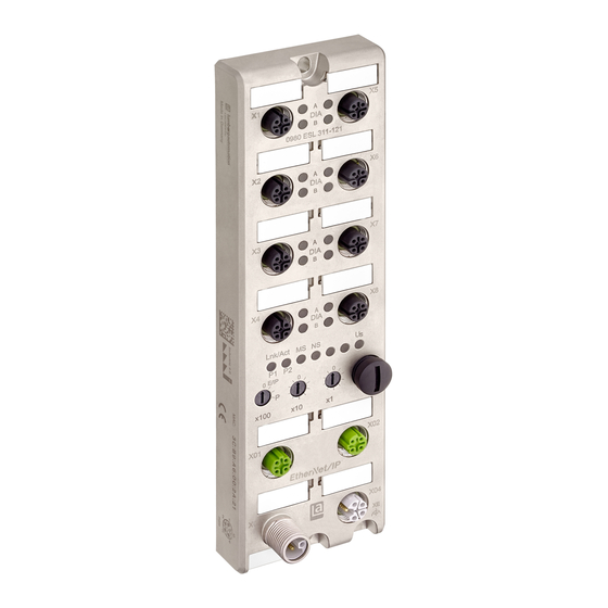
Page 20: Port Assignments
4.3 Port Assignments 4 Assembly and Wiring 4.3 Port Assignments All the contact arrangements shown in this chapter show the frontal view of the connection area for the connectors. 4.3.1 PROFINET Ports, M12 Socket, 4-Pin, D-Coded Color coding: green Figure 3: Schematic drawing, ports X01, X02 Port Signal Function... - Page 21 4 Assembly and Wiring 4.3 Port Assignments Figure 4: Schematic drawing, port X03 (IN) Figure 5: Schematic drawing, port X04 (OUT) Port Signal Function Power supply GND_U Actuator X03, X04 GND_U System/sensors Functional earth (+24 V) System/sensors (+24 V) Actuator Table 3: Assignment of ports X03, X04 Attention: For the input module 0980 ESL 301-xxx, the two contacts 1 and 5 are not required for the power supply to the actuators.
-
Page 22: Power Supply With M12 Power L-Coded
4.3 Port Assignments 4 Assembly and Wiring Attention: For modules with a 7/8" housing, use the "SELV and Limited Energy" power source. 4.3.3 Power Supply with M12 Power L-Coded Color coding: gray Figure 6: Schematic diagram of the M12 L-coding (connector), port X03 (IN) Figure 7: Schematic diagram of the M12 L-coding (socket), port X04 (OUT) Power supply Signal... -
Page 23: Ports For Sensors/Actuators
4 Assembly and Wiring 4.3 Port Assignments 4.3.4 Ports for Sensors/Actuators Design: M12 socket, 5-pin Color coding: black Figure 8: Schematic drawing, ports X1 to X8 Port 16DI 16DO 8DI/8DO Sensor/actuator +24 V DC n.c. +24 V DC (Ports X1..X4) n.c. -
Page 24: Configuration And Startup
TIA Portal After installation of the GSDML files for the LioN-R PROFINET modules, they are available at Further field devices > PROFINET IO > I/O > Belden Deutschland GmbH – Lumberg Automation > Lumberg LioN-P in the hardware catalog. - Page 25 5 Configuration and Startup 5.2 Configuration of LioN-P PROFINET Modules in TIA Portal You can also add your project to it for use by double clicking on a module in the network view. In the newly projected module click on Not assigned and choose the corresponding PROFINET interface.
-
Page 26: Assigning A Unique Device Name
5.2 Configuration of LioN-P 5 Configuration and Startup PROFINET Modules in TIA Portal The input and output addresses specified in the device summary can be changed. LioN-P 16DIO modules (0980-ESL-300-111, 0980-ESL-300-121, 0980- ESL-390-111, 0980-ESL-390-121, 0980-ESL-390-121-DCU1) have an extended I/O function scope. Different profiles (e.g. 16 DI/DO) or modules may be used in slot 1 of the subrack. - Page 27 5 Configuration and Startup 5.2 Configuration of LioN-P PROFINET Modules in TIA Portal PROFINET interface [X1] > Ethernet addresses check the automatically issued IP address and check if the controller and the module are located in the same Ethernet subsystem. If necessary, change the settings.
-
Page 28: Assigning Device Name To A Lion-P Module
5.2 Configuration of LioN-P 5 Configuration and Startup PROFINET Modules in TIA Portal 5.2.2 Assigning Device Name to a LioN-P Module To enable a participant to be assigned an IP address in a PROFINET network, each LioN-P module has to be issued with a device name. A participant search enables the detected PROFINET devices to be displayed. -
Page 29: Device Replacement Without Removable Media/Pd
5 Configuration and Startup 5.2 Configuration of LioN-P PROFINET Modules in TIA Portal 5.2.3 Device Replacement without Removable Media/PD PROFINET I/O devices that support the function of device replacement without removable media or a programming unit can be replaced by the same devices in an existing PROFINET network. -
Page 30: Parameter Settings For Lion-P Modules
5.2 Configuration of LioN-P 5 Configuration and Startup PROFINET Modules in TIA Portal A network topology is configured by connecting the PROFINET ports of the individual devices. These can be accessed using slot 0 of the PROFINET devices used. By displaying all the unused ports you can also define a suitable partner port in each instance. - Page 31 5 Configuration and Startup 5.2 Configuration of LioN-P PROFINET Modules in TIA Portal The parameter settings display is dependent on the module variant used as well as the version of the device description file. Each module has its own individual parameter record. Technical Manual LioN-P PROFINET Version 2.0 10/2017...
- Page 32 5.2 Configuration of LioN-P 5 Configuration and Startup PROFINET Modules in TIA Portal General Parameters Report Alarms: Activate/deactivate Global PROFINET alarm messages. Report Alarm U Activate/deactivate PROFINET alarm message for missing actuator supply voltage (U ). If the global PROFINET alarm messages are deactivated, this alarm is not registered. Report Alarm DO without U Activate/deactivate PROFINET alarm message for missing actuator supply voltage (U ) and actuation...
-
Page 33: Fast Start-Up (Fsu) / Prioritized Start-Up
5 Configuration and Startup 5.2 Configuration of LioN-P PROFINET Modules in TIA Portal The following options are available Set Low – Deactivation of output channel (digital value = 0) Set High – Activation of output channel (digital value = 1) Hold Last –... -
Page 34: Resetting Lion-P Modules To Factory Settings
5.2 Configuration of LioN-P 5 Configuration and Startup PROFINET Modules in TIA Portal 5.2.6 Resetting LioN-P Modules to Factory Settings To reset the LioN-P module to the factory settings you have to search in the TIA Portal for PROFINET participants that can be reached. In the main menu select Online >... -
Page 35: Media Redundancy Protocol (Mrp)
5 Configuration and Startup 5.2 Configuration of LioN-P PROFINET Modules in TIA Portal Functions > Reset to factory settings to reset the LioN-P module again to its original condition 5.2.7 Media Redundancy Protocol (MRP) Redundant PROFINET communication can be implemented with the LioN-P modules via a ring topology without the use of additional switches. - Page 36 5.2 Configuration of LioN-P 5 Configuration and Startup PROFINET Modules in TIA Portal Media redundancy can be configured using a LioN-P module through slot 0 of the device summary. PROFINET interface [X1] > Advanced options > Media redundancy The response monitoring time for LioN-P modules can use PROFINET interface [X1] >...
-
Page 37: Assignment Of Process Data
6 Assignment of Process Data 6.1 16DI Modules 6 Assignment of Process Data This chapter describes the assignment of controller process data to the I/O channels in slot 1 and the 16DI/DO DCU extension in slot 2 and 3 of the LioN- P modules. -
Page 38: Input Data
6.3 8DI/8DO Modules 6 Assignment of Process Data 6.2.1 Input Data This module provides two bytes of input data that reflect the current status of the output channels. Input Bit 7 Bit 6 Bit 5 Bit 4 Bit 3 Bit 2 Bit 1 Bit 0 Byte n... -
Page 39: Input Data
6 Assignment of Process Data 6.3 8DI/8DO Modules 0980 ESL 393-xxx-DCU1 6.3.1 Input Data This module provides two bytes of input data that reflects the current status of the input and output channels. Input Bit 7 Bit 6 Bit 5 Bit 4 Bit 3 Bit 2... -
Page 40: 16Di/Do Modules
6.4 16DI/DO Modules 6 Assignment of Process Data 6.4 16DI/DO Modules 0980 ESL 300-xxx 0980 ESL 390-xxx 0980 ESL 390-xxx-DCU1 The data structure for the process data in slot 1 is dependent on the IO mapping used. LioN-P DCU modules have an extended process data area in slot 2 and 3. -
Page 41: Input Data Profile 8Di/Do
6 Assignment of Process Data 6.4 16DI/DO Modules Output Bit 7 Bit 6 Bit 5 Bit 4 Bit 3 Bit 2 Bit 1 Bit 0 Byte n Byte n + 1 Table 12: Slot 1 The following applies here: 1A...8A: Target status of output channel A (contact pin 4) of the M12 socket connections 1 to 8. -
Page 42: Input Data Profile 16Di
6.4 16DI/DO Modules 6 Assignment of Process Data 1A...8A: Target status of output channel A (contact pin 4) of the M12 socket connections 1 to 8. 6.4.5 Input Data Profile 16DI This module provides two bytes of input data that reflect the current status of the input channels. -
Page 43: Output Data Profile 8Do
6 Assignment of Process Data 6.4 16DI/DO Modules Output Bit 7 Bit 6 Bit 5 Bit 4 Bit 3 Bit 2 Bit 1 Bit 0 Byte n Byte n + 1 Table 17: Slot 1 The following applies here: 1A...8A: Target status of output channel A (contact pin 4) of the M12 socket connections 1 to 8. -
Page 44: Output Data Profile 8Di/8Do
6.4 16DI/DO Modules 6 Assignment of Process Data 1A...4A: Actual status of input channel A (contact pin 4) of the M12 socket connections 1 to 4. 1B...4B: Actual status of input channel B (contact pin 2) of the M12 socket connections 1 to 4. -
Page 45: Output Data Dcu Extension
6 Assignment of Process Data 6.4 16DI/DO Modules Input Bit 7 Bit 6 Bit 5 Bit 4 Bit 3 Bit 2 Bit 1 Bit 0 Byte n 16 bit I/O DCU extension Byte n + 1 Table 21: Slot 2 (only LioN-P DCU modules) Input Bit 7 Bit 6... - Page 46 6.4 16DI/DO Modules 6 Assignment of Process Data Output Bit 7 Bit 6 Bit 5 Bit 4 Bit 3 Bit 2 Bit 1 Bit 0 Byte n 16 bit I/O DCU extension Byte n + 1 Table 23: Slot 2 (only LioN-P DCU modules) Output Bit 7 Bit 6...
-
Page 47: Diagnostic Properties Of The Modules
7 Diagnostic Properties of the 7.1 Channel Error Modules 7 Diagnostic Properties of the Modules The modules provide advanced diagnosis behavior, in particular for the output channels to determine errors in the transmission. The firmware of the modules differentiates between five distinct types of error. 7.1 Channel Error A channel error is determined by comparing the target value set by a controller and the actual value of the output channel. -
Page 48: Voltage Errors At M12 Slots (Sensor Short Circuit)
7.2 Voltage Errors at M12 Slots 7 Diagnostic Properties of the (Sensor Short Circuit) Modules of the module. The value of this parameter can range from 0 to 255 ms; the factory setting is 80 ms. The filter is used to avoid premature error messages when a capacitive load is activated or an inductive load is deactivated, and during other voltage peaks when a status changes. -
Page 49: Error In Actuator Power Supply
7 Diagnostic Properties of the 7.4 Error in Actuator Power Supply Modules Target value Actual value Comment Active Active OK, no diagnosis OK, no diagnosis Active Short circuit, channel indicator is red. Channel error bit in the diagnosis is set. Channel is locked after error is removed. -
Page 50: Error In System/Sensor Power Supply
7.5 Error in System/Sensor Power 7 Diagnostic Properties of the Supply Modules Attention: Every output channel that is active at the same time as the error occurs in supply voltage U is locked. This means that for correct operation, the output channel must be reset by the controller when the status of the supply voltage U has normalized again. - Page 51 7 Diagnostic Properties of the 7.6 Diagnostic Display in Integrated Modules Web Server Up to 5 bytes of diagnostics data can be shown in the process data area of the status page, depending on the module involved. The diagnostic bytes are structured as follows, going from the left to the right: Technical Manual LioN-P PROFINET Version 2.0 10/2017...
-
Page 52: 16Di Modules
7.6 Diagnostic Display in Integrated 7 Diagnostic Properties of the Web Server Modules 7.6.1 16DI Modules Bit 7 Bit 6 Bit 5 Bit 4 Bit 3 Bit 2 Bit 1 Bit 0 Byte 0 LV-U Byte 1 Table 27: Bit assignment for the 16DI modules 7.6.2 16DO Modules Bit 7 Bit 6... -
Page 53: Key
7 Diagnostic Properties of the 7.7 Alarm and Error Messages of Modules LioN-P/-R Modules via PROFINET Bit 7 Bit 6 Bit 5 Bit 4 Bit 3 Bit 2 Bit 1 Bit 0 Byte 3 X4-B X4-A X3-B X3-A X2-B X2-A X1-B X1-A Byte 4... -
Page 54: Alarm Assessment In Tia Portal
7.7 Alarm and Error Messages of 7 Diagnostic Properties of the LioN-P/-R Modules via PROFINET Modules 7.7.1 Alarm Assessment in TIA Portal In the TIA Portal, the user program execution is interrupted by triggering a diagnostic alarm, and a diagnostic block is activated. The following blocks are used: Cause of the alarm OB call... - Page 55 7 Diagnostic Properties of the 7.7 Alarm and Error Messages of Modules LioN-P/-R Modules via PROFINET Error type Reference Channel Number Channel Error Type Undervoltage of sensor Module 0x8000 0x0002 or actuator supply Sensor short-circuit M12 slot 0x0001 to 0x0008 0x0102 (Number of M12 slot) Actuator short-circuit...
-
Page 56: Integrated Web Server
8.1 Start Page/Status Page (Status) 8 Integrated Web Server 8 Integrated Web Server The LioN-P/-R modules are equipped with an integrated web server which makes functions available for the configuration of modules and display of status and diagnostic information. A standard web browser can be used to access the provided functions through an existing TCP/IP connection. -
Page 57: Force Mode
8 Integrated Web Server 8.1 Start Page/Status Page (Status) Pressing the Calculator symbol enables the mapping values to be assigned as an overview to the input and output addresses from the controller. Changes to the IO mapping can only be made in 16DI/DO modules through the controller. - Page 58 8.1 Start Page/Status Page (Status) 8 Integrated Web Server If Force Mode is activated in the offline mode through the web server, then a connection cannot be made to the controller. To use Force Mode in the online mode the web interface and Force Mode have to be activated through the controller parameterization.
-
Page 59: Configuration Page (Config)
8 Integrated Web Server 8.2 Configuration Page (Config) In a similar manner, the Simulation column can be used to simulate the input data of the individual channels before mapping into the process data. 8.2 Configuration Page (Config) When the Config menu item in the Web server menu bar is selected, the Configuration page opens. -
Page 60: Firmware Update For Profinet
8.2 Configuration Page (Config) 8 Integrated Web Server 8.2.1 Firmware Update for PROFINET Requirements PC with network interface Web browser (e.g. www.mozilla.org Performing Update 1. Reset into delivery status by setting the address switch to 979 and by running a power restart of the module. A period of 10 seconds should be waited (during the restart procedure the red BF/MS LED flashes on and off cyclically three times until the restart is completed / The 1st step is only necessary if the module was already operated on a PLC). - Page 61 8 Integrated Web Server 8.2 Configuration Page (Config) 7. Select new Update ZIP file on your local drive path to start the update. Clicking Search, marking and then double-clicking the selected ZIP file before then clicking the Upload button starts the update. Technical Manual LioN-P PROFINET Version 2.0 10/2017...
- Page 62 8.2 Configuration Page (Config) 8 Integrated Web Server 8. The firmware transfer lasts roughly 30 seconds (The procedure is visualized). 9. Close display “Update finished. Please restart the device” by clicking the OK button. 10.Run power restart of module. 11.The module is written with the new firmware version. 12.To check the result call up the system WEB page http://192.168.1.1.
-
Page 63: System Page
8 Integrated Web Server 8.3 System Page 14.Reset into delivery status by setting the address switch to 979 and by running a power restart of the module. A period of 10 seconds should be waited (during the restart procedure the red BF/MS LED flashes on and off cyclically three times until the restart is completed) 15.Set the address switch to 000. -
Page 64: Distributed Control Page (Dcu)
8.4 Distributed Control Page (DCU) 8 Integrated Web Server 8.4 Distributed Control Page (DCU) The Distributed Control function is an optional extension and it is only supported by LioN-P modules 0980 ESL 390-121-DCU1 and 0980 ESL 393-121-DCU1. This function enables control and monitoring tasks to be executed directly on the device using a DCU program. -
Page 65: Contact Page
8.5 Contact Page When the Contact menu item in the Web server menu bar is selected, the Contacts page opens. This provides information on the contact data for Belden Deutschland GmbH. Technical Manual LioN-P PROFINET Version 2.0 10/2017... -
Page 66: Reading The Process And Diagnostic Data
8.6 Reading the Process and 8 Integrated Web Server Diagnostic Data 8.6 Reading the Process and Diagnostic Data You have the option to read the process and diagnostic data for the LioN- P modules using the integrated web server. The web server provides the data in standardized JSON format. - Page 67 8 Integrated Web Server 8.6 Reading the Process and Diagnostic Data Content-Type: application/json {"consumed": [0,0], "produced": [0,0,0,0,0,0,0]} The response has the following object structure: Process data Produced (inputs): Array[a,b] Consumed (outputs): Array[a,b] Diagnostics Diag: Array[a,b,c,d,e] Technical Manual LioN-P PROFINET Version 2.0 10/2017...
-
Page 68: Technical Data
9.1 General 9 Technical Data 9 Technical Data 9.1 General Protection class IP 67 (only when the connectors are screwed in or when protective caps are used) Ambient temperature -25° C to +70° C (-13° F to +158° F) Ambient moisture 98% RF (for UL applications 80% PRF) Weight 480 g Housing material... -
Page 69: Bus System
9 Technical Data 9.2 Bus System 9.2 Bus System Protocol PROFINET IO RT is supported GSDML file LioN-P: GSDML-V2.3x- LumbergAutomation-0980ESL39x-xxx- yyyymmdd.xml Transfer rate 100 Mbit/s, full duplex Transmission procedure 100BASE-TX is supported Autonegotiation Manufacturer ID 0016A (Vendor ID) Device ID 0304 (DeviceID) Supported... -
Page 70: Power Supply For The Module Electronics/Sensors
9.3 Power Supply for the Module 9 Technical Data Electronics/Sensors 9.3 Power Supply for the Module Electronics/ Sensors Nominal voltage U 24 V DC (SELV/PELV) Voltage range 18-30 V DC Power consumption of module electronics Typically 120 mA Voltage level of the sensor power supply Min. -
Page 71: Power Supply For The Actuators
9 Technical Data 9.4 Power Supply for the Actuators 9.4 Power Supply for the Actuators Nominal voltage U 24 V DC (SELV/PELV) Voltage range 18-30 V DC Electric isolation Threshold value of the undervoltage detection Typ. 17 V Delay time for < 20 ms undervoltage detection Reverse polarity protection Operational indicator (U... -
Page 72: Inputs
9.5 Inputs 9 Technical Data 9.5 Inputs Input connection Type 3 as per IEC 61131-2 Nominal input voltage 24 V DC Input current at 24 V DC Typically 5 mA Short-circuit protection Channel type Normally open, p-switching Number of digital channels 16 with 16DI 0 with 16DO 8 with 8DI/8DO 16 with 16DI/DO... - Page 73 9 Technical Data 9.6 Outputs Output connection Type 2.0 A as per IEC 61131-2 Nominal output current per channel: See information 1 Signal status “1” Max. 2.0 A Signal status “0” Max. 1.0 mA (standard specifications) Signal level of the outputs: Min. (V –...
-
Page 74: Leds
9.7 LEDs 9 Technical Data Info 1: With inductive loads of consumption category DC13 (EN60947-5-1), the outputs can connect currents of 1.6 A at a frequency of 1 Hz. Info 2: Technically possible and approved under the following conditions: Looped sensor/system power supply max. 2.5 A Power supply cable STL 204 (5 x 1.0 mm Ambient temperature max. - Page 75 9 Technical Data 9.7 LEDs No data exchange flashing at 2 Hz No error Watchdog timeout; diagnostics present; system error DCP signal service is initiated via the bus flashing at 2 Hz, 3 sec No error message exists DCU/FM Blue DCU program stop Blue DCU program run flashing...
Need help?
Do you have a question about the lumberg automation LioN-P 0980 ESL 300 Series and is the answer not in the manual?
Questions and answers