
Subscribe to Our Youtube Channel
Related Manuals for Kodak 8000C


Summary of Contents for Kodak 8000C
- Page 1 KODAK 8000C Digital Panoramic and Cephalometric Extraoral Imaging System Installation Guide...
- Page 2 Notice Congratulations on your purchase of the KODAK 8000C Digital Panoramic and Cephalometric Extraoral Imaging System. Thank you for your confidence in our products and we will do all in our power to ensure your complete satisfaction. The Installation Guide for the KODAK 8000C Digital Panoramic and Cephalometric Extraoral Imaging System includes information on the cephalometric features.
-
Page 5: Table Of Contents
Fitting the Covers................5–20 KODAK 8000C Digital Panoramic and Cephalometric Extraoral Imaging System Installation Guide (SM736)_Ed 02... - Page 6 Contents Fitting the Cephalostat Covers............. 5–22 6—Maintenance Annual Maintenance.
-
Page 7: 1-About This Guide
Alerts you to a condition that might cause serious damage. IMPORTANT Alerts you to a condition that might cause problems. NOTE Emphasizes important information. Provides extra information and hints. KODAK 8000C Digital Panoramic and Cephalometric Extraoral Imaging System Installation Guide (SM736)_Ed 02 1–1... - Page 8 Conventions in this Guide 1–2 About This Guide...
-
Page 9: 2-Kodak 8000C Unit Overview
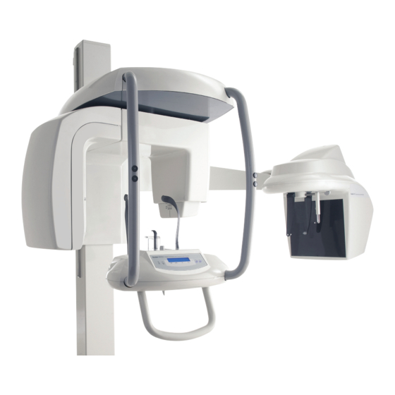
Chapter 2 KODAK 8000C UNIT OVERVIEW The KODAK 8000C digital panoramic and cephalometric unit is designed to carry out the following radiological examinations: • Panoramic • Maxillary Sinus • Temporomandibular Joints (TMJ) • Lateral cephalometric • Frontal (PA or AP) cephalometric •... -
Page 10: Mobile Components
The Cephalostat can be positioned either on the right or the left side of the KODAK 8000 unit. Mobile Components Figure 2-1 illustrates the up and down movement of the KODAK 8000C digital panoramic and cephalometric units mobile component and the rotation of the rotative arm. -
Page 11: General Functional Components
Temple supports Wall mounting brackets Unit mains connecting terminal Column upper cover Green warning lamp (ready state indicator) 22 Panoramic head cover Column connecting terminal Cephalostat arm KODAK 8000C Digital Panoramic and Cephalometric Extraoral Imaging System Installation Guide (SM736)_Ed 02 2–3... - Page 12 Door safety switch Cephalostat head and head top cover PC hosting the imaging and the acquisition Cephalostat head side cover software Ethernet outlet RJ45/1 Carbon fiber screen LAN RJ45/2 Head clamps and ear cones Nasion support 2–4 KODAK 8000C UNIT OVERVIEW...
-
Page 13: Digital Sensor Locations
Figure 2-3 illustrates the locations of the digital panoramic and digital cephalometric sensors of the KODAK 8000C digital panoramic and cephalometric units. Figure 2–3 KODAK 8000 and KODAK 8000C Units Digital Sensor Locations system KODAK 8000C Digital Panoramic and Cephalometric Extraoral Imaging System Installation Guide (SM736)_Ed 02 2–5... -
Page 14: Laser Locations
General Overview Laser Locations Figure 2-4 illustrates the location of the lasers of the KODAK 8000C digital panoramic and cephalometric units. Figure 2–4 KODAK 8000 and KODAK 8000C Units Laser Beam Locations Mid-sagittal plane positioning laser beam Frankfort plane positioning laser beam... -
Page 15: Control Panel
Reset button: Resets the unit arm to the initial position to enable the patient to enter and exit the unit. Laser beam button: Activates the laser positioning beams to correctly position the patient. KODAK 8000C Digital Panoramic and Cephalometric Extraoral Imaging System Installation Guide (SM736)_Ed 02 2–7... -
Page 16: X-Ray Remote Control Overview
You must press and hold the exposure button until the end of acquisition. Premature release of the exposure button interrupts the acquisition. Figure 2–6 X-Ray Remote Control Exposure button: launches image acquisition. 2–8 KODAK 8000C UNIT OVERVIEW... -
Page 17: Positioning Accessories And Replacement Parts
TMJ x2 and TMJ x4 nose rest Standard bite block Bite block for edentulous patients A set of right and left temple supports Single use sheaths for bite blocks (500 pcs box) KODAK 8000C Digital Panoramic and Cephalometric Extraoral Imaging System Installation Guide (SM736)_Ed 02 2–9... - Page 18 Positioning Accessories and Replacement Parts Accessory Description Head clamps with ear cones Nasion support 2–10 KODAK 8000C UNIT OVERVIEW...
-
Page 19: 3-Kodak 8000C Packaging
1200mm (L) x 800mm (D) x 1180mm (H) 80 kg Cephalostat covers • Documentation (User Guide and Installation Guide) Table 3–2 Components Product Description Quantity Cephalostat head KODAK 8000C Digital Panoramic and Cephalometric Extraoral Imaging System Installation Guide (SM736)_Ed 02 3–1... - Page 20 Standard Packaging Table 3–2 Components (Continued) Product Description Quantity Cephalostat arm Arm elbow tube End of the arm cover Head top cover Head side cover 3–2 KODAK 8000C PACKAGING...
-
Page 21: 4-Site Preparation Before Installation
Check the following ambient operating condition requirements of the x-ray room before installing the unit: • Temperatures: 5 ~35 °C • Relative humidity: 30 ~ 85% • Atmospheric pressure: 700 ~ 1060 hpa KODAK 8000C Digital Panoramic and Cephalometric Extraoral Imaging System Installation Guide (SM736)_Ed 02 4–1... -
Page 22: Unit Dimensions
Unit Dimensions Unit Dimensions 406 mm 1261 mm (15.98") (49.63") 306 mm (12.05") 10 mm (0.38") 440 mm 1810 mm (71.3") (17.3") The unit dimensions illustrated in the above figure are as follows: • Maximum height of the unit (2315mm) •... -
Page 23: Electrical Requirements
If other units are installed on the same line, interference and voltage fluctuations can cause the radiological unit to operate abnormally. We strongly recommend that a separate electrical line be dedicated to supply power to the KODAK 8000C unit. This line should be protected by a circuit breaker with a maximum current of: •... - Page 24 Electrical Requirements Figure 4–1 Electrical Diagram of the X-ray Room and Connections RJ45 K8000C 7bis General mains 7bis X-ray warning lamp connecting terminal Differential circuit breaker Column connecting terminals Red color actuator emergency stop push-button X-ray remote control Red color actuator emergency stop push-button 10 Door safety switch Red warning lamp, power ON indicator 11 Mains outlet (for electric tools)
- Page 25 • Maintain them in OFF (open) position until a deliberate action is performed. KODAK 8000C Digital Panoramic and Cephalometric Extraoral Imaging System Installation Guide (SM736)_Ed 02 4–5...
- Page 26 Electrical Requirements Table 4–2 Electrical Installation Specifications (Continued) • Specifications of 60 W 60 W Locate the red warning lamp (5) the warning lamps outside the x-ray room to indicate the unit is active (1 lamp at each (5) and (7) access point).
-
Page 27: X-Ray Room Requirement
IMPORTANT Install the unit where a minimum amount of space is provided to allow easy access for the patient or the maintenance technician (see Figure 4-2). KODAK 8000C Digital Panoramic and Cephalometric Extraoral Imaging System Installation Guide (SM736)_Ed 02 4–7... - Page 28 X-Ray Room Requirement Figure 4–2 Minimum X-Ray Room Space Configuration for K8000 and K8000C RJ45/1 RJ45/2 MINI 2350 mm (92.52") MINI 500 mm (19.68") 7bis Red color actuator emergency stop push-button X-ray remote control Red color actuator emergency stop push-button Door safety switch Red warning lamp, power ON indicator Mains outlet (for electrical tools)
-
Page 29: Computer System Requirements
Leave at least 1.5 m distance from the unit. The computer and the peripheral equipment must conform to the IEC 60950 standard. KODAK 8000C Digital Panoramic and Cephalometric Extraoral Imaging System Installation Guide (SM736)_Ed 02 4–9... - Page 30 Computer System Requirements 4–10 SITE PREPARATION BEFORE INSTALLATION...
-
Page 31: 5-Installing The Cephalostat
The tool references mentioned in this manual are ISO tool references. Technical Staff Requirements The installation requires the following number of technicians: Unit Component Technicians Head KODAK 8000C Digital Panoramic and Cephalometric Extraoral Imaging System Installation Guide (SM736)_Ed 02 5–1... -
Page 32: Opening The Box
Opening the Box Opening the Box Before opening the cephalostat assembly box make sure that you have the required tool. To open the cephalostat assembly box, follow these steps: 1. Remove the upper cardboard from the packaging. DO NOT cut through the cardboard. -
Page 33: Installing The Cephalostat Unit
To attach the arm, insert the screws on the column on the lower holes (A). Insert and then tighten the fixing screws (C). KODAK 8000C Digital Panoramic and Cephalometric Extraoral Imaging System Installation Guide (SM736)_Ed 02 5–3... - Page 34 Installing the Cephalostat Unit 2. Make sure that the tube (A) is for the appropriate side (by default it is for the right side position of the ceph), if not, unscrew the fixing screws and reposition it for the appropriate side. Insert all the way tube (A) inside the tube clamps (B) and screw in the fixing nut.Tigten the fixing screws of the tube clamps (B).
-
Page 35: Installing The Cephalostat Head
Left side ceph position, 7mm (B) • Right side ceph position, 22mm (C) 6 mm 7 mm 22 mm 4. Screw the fixing screws but do not tighten them. KODAK 8000C Digital Panoramic and Cephalometric Extraoral Imaging System Installation Guide (SM736)_Ed 02 5–5... - Page 36 Installing the Cephalostat Unit 5. Correctly position the cephalostat head using a spirit level (C) placed as shown in the figure. Tighten the fixing screws (B) to adjust with the spirit level (C). 4 mm 6. Correctly position the cephalostat head using a spirit level (D) placed as shown in the figure.
- Page 37 (A = B). To adjust the height use the tube fixing nut (C), see step 2 of the procedure. 8. Insert the cables (B) inside the elbow tube (A) tube. KODAK 8000C Digital Panoramic and Cephalometric Extraoral Imaging System Installation Guide (SM736)_Ed 02 5–7...
-
Page 38: Wiring The Cephalostat Head
Installing the Cephalostat Unit Wiring the Cephalostat Head 9. Pull the cables out of the elbow tube (A). Remove the adhesive tape. Connect the following wiring in the following order: Cable ... On the ... To ... 967/Alim Lambda/CN1 Power supply board Green and yellow cable Next to power supply box Ground screw Ethernet Pano (with ferrite) -
Page 39: Wiring The Cephalostat To The Unit Head
J21(adapter board CJ664 v4) (E “R”) 39/CJ699/J9 & 40/CJ699/J9 CJ699 J9 (for right side ceph) (E “L”) 39/CJ699/J9 & 40/CJ699/J9 CJ699 J9 (for left side ceph) KODAK 8000C Digital Panoramic and Cephalometric Extraoral Imaging System Installation Guide (SM736)_Ed 02 5–9... -
Page 40: Post-Installation Control
Before the post-installation control, check that: • The installation of the unit is complete. • The installation of the KODAK dental imaging software is complete. • You have the test tool. • You have raised the digital sensor to ceph mode. - Page 41 Use the fixing screws (B) to adjust the horizontal inclination. Tighten the fixing screws (A) when you have reached the desired adjustment. 2.5 mm 4 mm KODAK 8000C Digital Panoramic and Cephalometric Extraoral Imaging System Installation Guide (SM736)_Ed 02 5–11...
-
Page 42: Adjusting The Height Of The Cephalostat Head
Post-Installation Control Adjusting the Height of the Cephalostat Head To adjust the height of the cephalostat head, follow these steps: 1. Position the head clamps in a lateral position. 2. Access the Cephalometric Acquisition Window. In the Program pane, click 3. - Page 43 5. If needed, adjust the height, using the cephalostat arm screws (A). Untighten slightly the screws (A) and lift the cephalostat head to the correct height. Tighten the cephalostat arm screws (A). KODAK 8000C Digital Panoramic and Cephalometric Extraoral Imaging System Installation Guide (SM736)_Ed 02 5–13...
-
Page 44: Adjusting The Ear Cones Alignment
Post-Installation Control Adjusting the Ear Cones Alignment To adjust the ear cones alignment, follow these steps: 1. Position the head clamps in a lateral position. 2. Access the Cephalometric Acquisition Window. In the Program pane, click 3. Launch an x-ray using the x-ray remote control. The ear cone ball (A) must be at the center of the head clamps circle (B). -
Page 45: Adjusting The Nasion Support
2. Access the Cephalometric Acquisition Window. In the Program pane, click 3. Launch an x-ray using the x-ray remote control. The nasion support must be perpendicular to the ear cones. KODAK 8000C Digital Panoramic and Cephalometric Extraoral Imaging System Installation Guide (SM736)_Ed 02 5–15... - Page 46 Post-Installation Control 4. In the Imaging Window, on the drawing toolbar, click . On the acquired image, draw a perpendicular line between the center of the ear cones and the nasion support holes to check that the nasion support is positioned vertically. The resulting value must be A = B ±3mm.
-
Page 47: Adjusting The Cephalometric Frankfurt Positioning Laser
3. Make sure that the cephalometric Frankfurt positioning laser beam is projected in the middle of the ear cone. 4. If needed, adjust the laser using the fixing screw of the laser socket. 5. Replace the generator front cover. KODAK 8000C Digital Panoramic and Cephalometric Extraoral Imaging System Installation Guide (SM736)_Ed 02 5–17... -
Page 48: Checking The Image Quality
Post-Installation Control Checking the Image Quality To check the image quality, follow these steps: 1. Raise the nasion support. 2. Open the head clamps. 3. Position the image quality phantom (A) at the center of the digital sensor. 4. Access the Cephalometric Acquisition Window. In the Program pane, click 5. - Page 49 Post-Installation Control 8. Save the image. Use this image as reference for a later image quality verification. KODAK 8000C Digital Panoramic and Cephalometric Extraoral Imaging System Installation Guide (SM736)_Ed 02 5–19...
-
Page 50: Fitting The Covers
Fitting the Covers Fitting the Covers WARNING Before fitting the covers, you MUST switch off the unit. Before fitting the covers, check that: • All the screws in the wall and the floor have been tightened. • All the screws attaching the head and the fixed arm to the column have been tightened. - Page 51 4. Fit the inside column cover (F) and position and attach securely the ON/OFF button to the cover with the fixing screws. Screw and tighten the fixing screws of the column cover. You can fit the cephalometric covers now. KODAK 8000C Digital Panoramic and Cephalometric Extraoral Imaging System Installation Guide (SM736)_Ed 02 5–21...
- Page 52 Fitting the Covers Fitting the Cephalostat Covers To fit the cephalostat covers, follow these steps: 1. Fit the cephalostat end of the arm cover (A) and screw the fixing screws. 2. Fit the cephalostat head side covers (B) and screw the fixing screws. 3.
- Page 53 If the results of any of these inspections are unsatisfactory, refer to the Service Manual in order to rectify any problems. If there is any doubt, do not operate the unit. KODAK 8000C Digital Panoramic and Cephalometric Extraoral Imaging System Installation Guide (SM736)_Ed 02 6–1...
- Page 54 Annual Maintenance 6–2 Maintenance...
Need help?
Do you have a question about the 8000C and is the answer not in the manual?
Questions and answers
ERROR53 MESSAGE