Advertisement
Quick Links
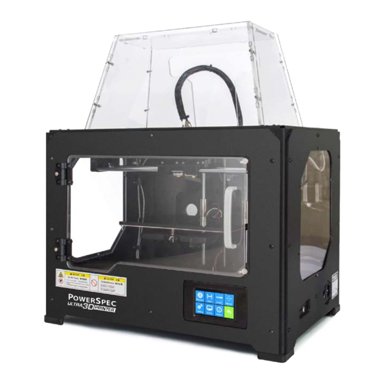
PowerSpec Ultra 3D Printer Start-up Guide
Table of Contents
1 What's Included in the Box?...........Page 3
2 Un-boxing...........................................Page 4
3 Initial Hardware Installation............Page 6
4 Software Instruction.........................Page 8
5 Filament.............................................Page 24
6 Initial Print.........................................Page 27
Advertisement

Related Manuals for PowerSpec Ultra

Summary of Contents for PowerSpec Ultra
- Page 1 PowerSpec Ultra 3D Printer Start-up Guide Table of Contents 1 What's Included in the Box?...Page 3 2 Un-boxing…………………………………….Page 4 3 Initial Hardware Installation…………Page 6 4 Software Instruction…………………….Page 8 5 Filament………………………………………Page 24 6 Initial Print…………………………………..Page 27...
- Page 2 PRECAUTIONS: Please ensure this page is read carefully prior to setting up or operating the 3D printer. The 3D printer is very sensitive to static electricity, so please ensure sure you connect to a properly grounded surge protected power outlet. Before repairing or making any alterations to the 3D printer, it is essential that the machine is turned off and the power cord is unplugged.
- Page 3 What's Included in the Box? Along with your 3D printer, the box also contains the following: In the two long boxes on top: • Power cord x 1pc • USB type A to type B cable x 1pc • Sensor Line x 1pc •...
- Page 4 Un-packing The 3D printer was carefully packaged at the manufacturing facility. Please follow the unpacking steps as noted below. CAUTION Handle the package and its contents with extreme care and do not use any unnecessary force. Do not remove the thin yellow film from the heating plate. It is heat resistant tape that improves the adhesion of the extruded plastic to the plate.
- Page 5 Please remove both of the foam supports holding the printer in place and make certain that you can grasp the frame firmly, and then lift the printer out of the carton. Now you can see the top of the printer along with more boxes inside. The large box with the black wire is the accessory box.
- Page 6 Initial Hardware Installation You will need the two shortest silver screws from the kit found in the accessory box, and the appropriate hex wrench. First, lower the build platform by using one of the methods described in the previous section. Holding the extruder by both sides, take it out of the accessory sleeve and position it on the extruder seat with the fan facing forward.
- Page 7 Finally install the filament on the spool holders Congratulations! You have completed the initial hardware installation! You are now ready to start printing. Please proceed to the next step: Software Installation.
- Page 8 Software Installation 1.1 Preparation A. Insert the included SD card with 3D printer software into your computer. We have already prepared the latest driver installation package in the SD card. Copy the RAR program to your PC. 1.2 Installation & Startup A.
- Page 9 Turn and rotate your model Scale the size of your model Select right or left extruder you want to print with Print it directly with your 3D printer or export to your SD card. You can use Powerprint software to control 3D printer and perform printing tasks. 2.1 Load File You can load a model file or Gcode file into the software by following any of the following six methods: A.
- Page 10 2.3 Change Views Change your view of the model by moving, rotating, scaling the view, and so on. 2.3.1 Move You can move the view of printing frame in the software interface using the following three methods: A. Press and hold the left button of the mouse and then drag the cursor. B.
- Page 11 Note: Generally, we suggest you to click the Center and On Platform buttons after adjusting location of the model to make sure the model within the printing scope and sticking to HBP. Only click On Platform button if you want to print the model in a specified position. 2.4.2 Rotate When the model is selected, you can change the orientation on the build platform using the following two methods:...
- Page 12 2.4.5.3 Select ALL Using the following two methods, you can select all models in the scene. A. Click Edit-> Select ALL menu. B. Use the shortcut Ctrl+A. Note: When models are too small to be seen, or out of viewing scope, please click Center and On Platform buttons after selecting all models to bring them to the printing scope.
- Page 13 2.5.2 Clear Supports Select this option to empty all the supports of your model. Click Edit->Undo in the menu or Ctrl+Z to undo this operation. 2.5.3 Add Select this option to add supports. After selecting this option, move your mouse to where you want to add the support, and then left-click the mouse to select the start point of support structure.
- Page 14 2.8.3 Print 2.8.3.1 Generate Gcode File In order to print, you need to slice the model file to generate a gcode file by using the following steps: 1. Click Print -> Print menu or Print button on top of the software interface, a pop-up dialog box will open for slicing.
- Page 15 2.8.3.2 Explanation of Slicing settings...
- Page 16 A. Preview: Select this option to preview the Gcode file when slicing is finished. B. Print When Slice Done: Select this option to directly print the model. C. Slice Engine: Three slice engines are provided: Slic3r, Skeinforge and ffslicer. Different slice engines have different configurations.
- Page 17 A. Layers a. Layer Height is the height of each layer. The lower the value of layer height is, the finer the surface of the model will be . b. First Layer Height exists when users choose Slic3r as the slice engine, and it affects the adhesion degree between model and platform.
- Page 18 2.9 Printer Operations 2.9.1 Connect / Disconnect You can connect the 3D printer to Powerprint software via a USB cable or WIFI (if equipped). The machine icon in the bottom right corner of the software interface displays a broken chain pattern means disconnected, while displaying an unbroken one means connected.
- Page 19 AP Mode Setup: In the setup section of AP Parameters, you should change the SSID, password, IP and subnet mask. To setup WIFI mode as AP mode, click Save and reboot and AP mode should be set successfully. STA Mode Setup: In the setup section of STA Parameters, you can change the SSID, Internet Password, and DHCP Mode.
- Page 20 A. Jog Controls a. Jog Mode: You can set the distance the extruder or the platform moves by a single jog click time. b. Direction Buttons: These six blue-arrow buttons are set to control the movements in the X/Y/Z directions. Click the direction buttons of the x-axes and y-axes to control the horizontal movements of the extruder.
- Page 21 D. Stepper Motor Control To control the stepper motor click the Open button to lock the stepper motor to prevent adjusting the position of the extruder and platform manually and the Close button will unlock it so manual adjustment of the extruder and platform can be made.
- Page 22 2.9.5 Machine Information When the printer has been connected, click Tools->Machine Information menu to review the information about the machine, including MACHINE TYPE, MACHINE NAME, FIRMWARE VERSION, etc. 2.9.6 Driver Installation A. Open the root directory of the software B. Open the driver folder located in the root directory and find the driver. There are two driver installation packages, please install one of them according to your computer system.
- Page 23 Filament To make the process of feeding or withdrawing the filament easy, please follow the next few steps carefully: After inserting the filament into the feeding hole, do not force it further until the extruder temperature reaches 200°C or more. Once the machine reaches this point, you will feel the filament being pulled into the extruder head. Filament Install First, remove the filament guide tube from the extruder head.
- Page 24 Select [ Filament ] and [ Load Left ]. 3. Wait for the extruder to heat up to the operating temperature. The extruder will alert you once it is at the operating temperature. Load the filament by inserting it into the extruder at an upright angle. 4.
- Page 25 Initial Print CAUTION The printer build plate has been leveled perfectly before leaving factory. However, it may move during shipping so please verify the build plate is level before starting a print. See instructions below. First, make sure that you’ve completed all the steps in the Un-boxing and Hardware Setup section.
- Page 26 Press [ NEXT ] and wait for the extruder to move to the second position. Slide the paper back and forth again, and adjust the screws to create the same amount of friction as in the previous step. Press [ NEXT ] again and repeat the same leveling technique. Press [ NEXT ].
- Page 27 Single-Extrusion Print 1. Open Powerprint by double-clicking on the icon. 2. Click on [ Load ] and choose a .stl file from hard drive. 3. The object will then be shown on the screen. 4. Click on the object and then click on [ Extruder ], select [ Use left extruder ]. Left extruder will be used for illustration purposes.
- Page 28 4. Powerprint will begin slicing the 3D model. 5. After the object is done slicing, take the SD card from the computer. Insert it into the SD card slot on the 3D printer. 6. Turn on the 3D printer. Make sure the build plate is leveled and that filament is loaded in the left extruder. 7.
- Page 29 5. Referring to the example above for reference: Reboot the WIFI SSID of Dreamer to establish connection, then connect the Dreamer-TV1 to the Internet under the AP mode of the computer, make sure that Dreamer and the computer access the same WIFI, then open the FlashPrint and click on Menu—Print—Connect successfully. Choose WIFI as the link mode, input the IP address of user Internet (The IP address will be shown on the screen of the 3D printer) to the IP port below, and then click ON to connect.
Need help?
Do you have a question about the Ultra and is the answer not in the manual?
Questions and answers