Table of Contents
Advertisement
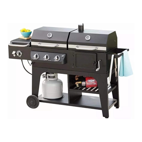
Hybrid Grill
Infrared, Gas & Charcoal Cooking System
Model Number:
GR2071013-MM-01
ASSEMBLY & OPERATING INSTRUCTIONS
This instruction manual contains important information necessary for the
proper assembly and safe use of the appliance.
Read and follow all warnings and instructions before assembling/using
the appliance.
Follow all warnings and instructions when using the appliance.
Keep this manual for further reference
Please do not withdraw all parts from the packing boxes immediately!!
Each assembly step in this instruction manual has instructed you to find the
particular part(s) from the packing box quickly. We strongly recommend that you
read through the assembly procedure before proceeding assembly.
DO NOT return product to the retail store!!
For assistance, contact customer service at
or at 1-888-837-1380, Mon to Fri, 8:00am – 5:00pm Pacific Standard time
For Outdoor Use Only
ATTENTION
Should you encounter any problem,
CALL US FIRST.
WE CAN HELP.
1 of 48
customerservice@rankam.com
20170928-Ver1
Advertisement
Table of Contents

Related Manuals for Member's Mark GR2071013-MM-01


Summary of Contents for Member's Mark GR2071013-MM-01
- Page 1 Hybrid Grill Infrared, Gas & Charcoal Cooking System Model Number: GR2071013-MM-01 ASSEMBLY & OPERATING INSTRUCTIONS For Outdoor Use Only This instruction manual contains important information necessary for the proper assembly and safe use of the appliance. Read and follow all warnings and instructions before assembling/using the appliance.
-
Page 2: Prop 65 Warning
DANGER If you smell gas: 1. Shut off gas to the appliance. 2. Extinguish any open flame. 3. Open lid. 4. If odor continues, keep away from the appliance and immediately call your gas supplier or fire department. Failure to follow these instructions could result in fire or explosion which could cause property damage, personal injury or death. - Page 3 GAS GRILL GENERAL WARNINGS WARNING This outdoor cooking gas appliance shall be used only outdoors and shall not be used in a building, garage or any other enclosed area. This outdoor cooking gas appliance is not intended to be installed in or on boats.
-
Page 4: Lp Gas Cylinder
USE OF LP GAS CYLINDER AND INSTALLATION BEFORE INSTALLING: The installation must conform with local codes or, in the absence of local codes, with either the National Fuel Gas Code, ANSI Z223.1/NFPA 54, Natural Gas and Propane Installation Code, CSA B149.1, or Propane Storage and Handling Code, B149.2,or the Standard for Recreational Vehicles, ANSI A 119.2/NFPA 1192, and CSA Z240 RV Series, Recreational Vehicle Code, as applicable. - Page 5 WARNING Place dust cap on cylinder valve outlet whenever the cylinder is not in use. Only install the type of dust cap on the cylinder valve outlet that is provided with the cylinder valve. Other types of caps or plugs may result in leakage of propane. DANGER ...
-
Page 6: Installing Gas Cylinder
INSTALLING GAS CYLINDER Check that cylinder valve is closed by turning knob clockwise. Cylinder Place cylinder to cylinder fixture which is at the bottom cart of the grill per picture shown. Cylinder WARNING: Keep the fuel supply hose Fixture away from any heated surfaces. WARNING ... - Page 7 Turn the burner valves off. Turn the tank valve off fully (turn clockwise to stop). Detach the regulator assembly from the tank valve by turning the quick coupling nut counterclockwise. LEAK TEST WARNING DO NOT SMOKE WHILE CONDUCTING LEAK TEST. ...
-
Page 8: Lighting Instructions
LIGHTING INSTRUCTIONS BEFORE LIGHTING WARNING Inspect the gas supply hose prior to turning the gas “ON”. If there is evidence of cuts, wear, or abrasion, it must be replaced prior to use. Do not use the grill if the odor of gas is present. ... - Page 9 LIGHTING THE SIDE BURNER (Side burner): DANGER Never close the SIDE BURNER LID during operation 1. Read all instructions before lighting. 2. Open lid during lighting. 3. Push and turn main burner knob slowly to HI. The side burner should light immediately. 4.
-
Page 10: Flame Characteristics
Infrared Side Burner Usage Tips Infrared burners are commonly used in steak restaurants and they can quickly cook steaks or other thick meats. The infrared radiation generated by the burner immediately sears the outside of meat, locking in the moisture and giving the meat a charcoal-like taste. -
Page 11: Grease Tray
MAINTENANCE GUIDE Before cleaning the grill, place it in an area clear and free from combustible materials, gasoline and other flammable vapors and liquids. Do not obstruct the flow of combustion and ventilation air. GREASE TRAY The grease tray should be emptied and wiped down periodically and washed with a mild detergent and warm water solution. - Page 12 Removing the main burner(s): 1. Turn all Burner Valves to the full OFF position. 2. Turn the LP Gas tank valve to the full OFF position. 3. Detach the LP Gas regulator assembly from your gas cylinder. 4. Remove the Cooking Grates and Heat Distribution Plates from your grill. 5.
-
Page 13: Charcoal Grill General Warnings
WARNING For safe operation ensure the Gas Valve Assembly Orifice is inside the Burner Tube before using your grill. See figure. If the Orifice is not inside the Burner Tube, lighting the Burner may cause explosion and/ or fire resulting in serious bodily injury and/or property damage. - Page 14 deck railings, walls or other combustible material. DO NOT use grill under overhead unprotected combustible construction. For outdoor use only. Do not use this grill for other than its intended purpose. For household use only. Do not use this grill for other than its intended purpose. ...
-
Page 15: Preparation For Use & Lighting Instructions
PREPARATION FOR USE & LIGHTING INSTRUCTIONS WARNING OUTDOOR USE ONLY. DO NOT OPERATE GRILL INDOORS OR IN AN ENCLOSED SPACE. Never use grill indoors. Carbon Monoxide poisoning can lead to death. Curing your grill Prior to your first use of the Grill, follow the instructions below carefully to cure your grill. Curing your grill will minimize damage to the exterior finish as well as rid the grill of paint odor that can impart unnatural flavors to the first meal prepared on the grill. - Page 16 Step 5 Place lump or briquette charcoal on top of grate in chimney starter until full. Underneath grate place balled up paper and light with match or lighter thru holes in bottom of chimney sides. Once paper lights, fire will spread up thru charcoal until entire column is glowing red in the bottom with ash formation on top.
-
Page 17: Flavoring Wood
NOTE: To extend the life of your grill, make sure that hot coals and wood do not touch the walls of grill. IF USING CHARCOAL CHIMNEY STARTER, PROCEED TO STEP 4. If you choose to use charcoal lighting fluid, ONLY use charcoal lighting fluid approved for lighting charcoal. -
Page 18: Regulating Heat
Additional flavoring wood should not have to be added during the cooking process. However, it may be necessary when cooking very large pieces of food. Follow instructions and cautions in the “Adding Charcoal/Wood During Cooking” section of this manual to avoid injury while adding wood. -
Page 19: After-Use Safety
AFTER-USE SAFETY CAUTION Always allow grill and all components to cool completely before handling. Never leave coals and ashes in grill unattended. Make sure coals and ashes are completely extinguished before removing. Before grill can be left unattended, remaining coals and ashes must be removed from grill. Use caution to protect yourself and property. -
Page 20: Packing List
Packing List ATTENTION Please do not withdraw all small parts from the packing boxes immediately Each assembly step in this instruction manual has instructed you to find the particular part(s) from the packing box quickly. We strongly recommend that you read through the assembly procedure before proceeding assembly. - Page 21 Box D Box A Part 17 Left Pivot Leg Part 1 Chimney Cover Part 18 Right Pivot Leg Part 5 Air Vent Part 33 Left Wheel Leg Part 7 Bezel 6pcs Part 34 Right Wheel Leg Part 21 Crank Part 25 Bottle Opener Box B Part 26...
-
Page 22: Product Diagram
Product Diagram 22 of 48 20170928-Ver1... -
Page 23: Component List
Component List 1.Chimney Cover 2.Charcoal Chimney 3.Left Lid 4.Grill Body Assembly (Gas) Assembly Box D Qty: 1 pc Box C Qty: 1 pc Qty: 1 pc Qty: 1 pc 5.Air Vent 6.Grill Handle 7.Bezel 8. Lid Handle Box D Qty: 1 pc Box C Qty: 1 pc Box D... - Page 24 21. Crank 22.Side Burner 23.Side Burner 24.Side Burner Assembly Cooking Grate Control Panel Box D Qty: 1 pc Box E Qty: 1 pc Box B Qty: 1 pc Box G Qty: 1 pc 25.Bottle Opener 26.Control Knob 27.Side Burner 28. Side Burner Bracket (Left) Bracket (Right) Box D...
-
Page 25: Hardware List
Hardware List Item No. Item name Diagram M6 X 12mm Bolt (Black) M12 Washer Plastic Rivet M6 X 15mm Bolt (Black) Hex Nut Wrench M6 X 25mm Bolt (Black) Cotter Pin M6 Locking Nut M6 X 12mm Bolt (Sliver) 25 of 48 20170928-Ver1... - Page 26 Hardware List M6 X 12mm Hexagonal Bolt M6 X 35mm Bolt (Black) M8 Cap Nut Spring Hinge Pin Screwdriver 26 of 48 20170928-Ver1...
- Page 27 Replacement Part List (I) 27 of 48 20170928-Ver1...
- Page 28 Replacement Part List (II) Side Burner Ignition Chimney Cover Air Vent Electrode With Wire Charcoal Chimney Grill Handle Side Burner Valve Side Burner Electrode Left Lid Assembly (Gas) Bezel Cover Side Burner Cooking Left Lid (Gas) Lid Handle Grate Side Burner Control Thermometer Upper Hinge Panel...
-
Page 29: Assembly Procedures
Assembly Procedures Step 1: Attach the Leg Brace (16) to the Left Wheel Leg (33) and Right Wheel Leg (34) by using 4 pcs of Bolts (A). Tips. Each “Wheel Leg” has a hole at the bottom. (Please see the Gray Triangles) Step 2: Attach the Leg Brace (16) to the Left Pivot Leg (17) and Right Pivot Leg (18) by using 4 pcs of Bolts (A). - Page 30 Step 3: Place the legs on the floor at upside down position per shown. Attach the 2 pcs of Middle Brace (15) by using 8 pcs of Bolt (A) Tips. Make sure the middle bracket must be on top during the assembly and pointing into inside. (Please see the Gray Triangles) Step 4: Attach the Bottom Shelf (20) to the Legs assembly by using 4 pcs of Bolts (A) Tips: Make sure the big tank hole of bottom shelf should be placed at the side of SHORT leg opposite the leg adjustor.
- Page 31 Step 5: Attach the 2 pcs of Wheel (35) to short leg sides by using 2 pcs of Wheel Washer (B) and Wheel Axle (36). The Wheel Axle can be fastened the Hex Nut Wrench (E). Attach the Wheel Cover (37) to the wheels. E (1pc) Step 6: Attach the Middle Panel (39) to the bottom cart by using 4pcs of Bolts (A).
- Page 32 Step 7: Attach the Bottom Rack (14) to the bottom cart by using 2 pcs of Bolt (A). Tip: Attach the bottom rack to bracket first per (a), then fasten the bolts per (b). (Please see the Gray Triangles). Step 8: Attach the Tank Fixture (38) to the big hole of bottom cart by snapping in with 3 pcs of Plastics Rivet (C). 32 of 48 20170928-Ver1...
- Page 33 Step 9: This step requires 2 people! Attach the Grill Body Assembly (4) on the bottom cart by using 6 pcs of Bolt (D) . Tips: Do not tighten all the screws during installing each bolt. Make sure the grill body should be well aligned with the bottom cart braces then tighten all bolts.
- Page 34 Step 11: Rotate the Crank (21) into the crank holder on the charcoal side of grill body then using 1 pc of Cotter Pin (G) to fix the crank. Step 12: Attach the Grill Handle (6) to the grill body by using 4 pcs of Hexagonal Bolt (J). These bolts can be fastened by Hex Nut Wrench (E).
- Page 35 Step13: Attach Left and Right Side Burner Bracket (27 and 28) to the grill body by using 2 pcs of Bolt (A). Step14: Attach the Side Burner Assembly (22) on the side burner brackets per following shown. 35 of 48 20170928-Ver1...
- Page 36 Step15: Secure the side burner assembly by using 2pcs of Bolt (A). Step16: Attach the Bottle Opener (25) to the Side Burner Control Panel (24) by using 2 pcs of Bolt (I). 36 of 48 20170928-Ver1...
- Page 37 Step 17. Take out the side valve with gas regulator assembly from main control panel at grill side per following shown. Understand the construction of side burner gas components, it would help you proceed the side burner assembly in next several steps.
- Page 38 ATTENTION: DO NOT OVER TWISTING THE FLEXIBLE STAINLESS STEEL GAS TUBE Step 18: GENTLY bend the Flexible Stainless Steel Gas Tube its route is similar to illustration (a). Loosen the pre-assemble screws at Side Burner Gas Valve per illustration (b) Tips: Do not let the pre-assemble screws get grid of the gas valve.
- Page 39 Step 19: Attach the Side Burner Gas Valve to Side Burner Control Panel per illustration (a) and (b). Before fastening the pre-assembled screws of gas valve, make sure the gas valve should be pushed up at correct position per illustration (c). 39 of 48 20170928-Ver1...
- Page 40 Step20: Connect the Ignition Wire with Ignition Wire Junction first. Attach the Side Burner Control Panel to the Control Panel Bracket. Remember to check that the top lip of the side burner control panel should be hooked onto the side burner control panel brackets.
- Page 41 Step 21: Attach the side burner control panel to the side burner per shown. Secure the side burner control panel by using 2 pcs of Bolt (A). Tips: Before secure the side burner control panel. Double check following points: (1) Make sure the Gas Valve Nozzle has already engaged with the Side Burner Venturi. You can see and check through the observation hole at side burner bracket.
- Page 42 Step 23: Attach the Control Knobs (26) to each gas valve. Step 24: Attach the Lid Handle (8) and Bezel (7) to the side burner lid by using 2 pcs of Bolt (D) 42 of 48 20170928-Ver1...
- Page 43 Step 25: Attach Lid Handle (8) and Bezel (7) to Right Lid Assembly (19) and Left Lid Assembly (3) by using 4 pcs of Bolt (F) respectively. Attach Upper Hinge (9) to the Right Lid Assembly (19) and Left Lid Assembly (3) by using 8 pcs of Bolt (K) respectively.
- Page 44 Step27: Attach the Lower Hinge (10) to the back of grill body by using 8pcs of Bolt (K). Tips: Remember to check the shape of the hinges and make sure to use the correct hinges for this step. (Please see the grey triangles) Step 28: Attach the Right and Left Lid on the grill body.
- Page 45 Step 29: Put the Flame Tamer (13) over the gas burners first. Then put Side Burner Cooking Grate (23), Gas Grill Cooking Grate (32) and Charcoal Grill Cooking Grate (12) to the grill body. The Cooking Grate Lifter (31) is for lifting up the cooking grates during the cooking. Step 30: Attach the Warming Rack (11) to the grill chambers.
- Page 46 Step31: Take out the grease tray from the grill body. Attach Charcoal Grease Tray Handle (29) by using 2 pcs Bolt (A). Also put the Grease Cup (30) to the Grill body as shown. Assemble Completed 46 of 48 20170928-Ver1...
-
Page 47: Troubleshooting
Troubleshooting Problem Possible Cause Prevention / Cure Burner will not light using “Ignition Wire/or electrode covered with Clean wire and/or electrode, with Burner”. cooking residue. rubbing alcohol. Electrode and burner are wet. Wipe dry with cloth. Electrode cracked or broken – Call customer Service to replace sparks at crack electrode. -
Page 48: Limited Warranty
LIMITED WARRANTY Manufacturer warrants this Product to be free from defects in workmanship and materials for a period of Ninety (90) days from the date of purchase, PROVIDED claims are submitted, in writing, with proof of purchase. If any part of this item fails because of a manufacturing defect within the Limited Warranty Period, Manufacturer offers to replace such part(s) provide that such parts have not been improperly repaired, altered, or tampered with or subject to misuse, abuse or exposed to corrosive conditions.
Need help?
Do you have a question about the GR2071013-MM-01 and is the answer not in the manual?
Questions and answers