Advertisement
Quick Links
Advertisement

Related Manuals for Rover OMNIA 7000


Summary of Contents for Rover OMNIA 7000
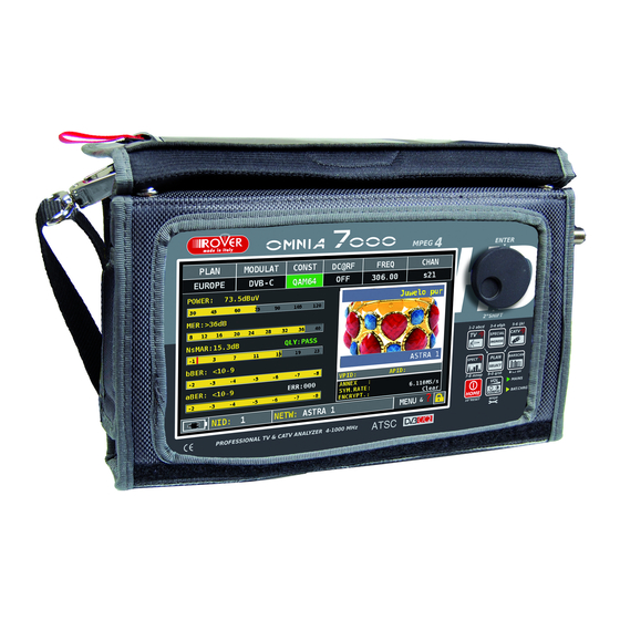
- Page 1 USER’S GUIDE TFT 16:9 TFT 16:9 TFT 16:9 TFT 16:9 www.roverinstruments.com...
- Page 2 GET TO KNOW YOUR OMNIA 7000 FRONT PANEL ___________________________________ To turn on press To turn off press and the ‘HOME’ key. hold the ‘HOME’ key Use the wheel to navigate across the screen and adjust the values Select a menu...
- Page 3 ____________________________________________________ LAN Eternet RJ45 OPTIC IN: FC-ST-SC opt. USB B SW upgrades RF out “F” 75 USB A memory stick ASI OUT (opt.) Power Supply input (12 V DC - 1A) 10 = ASI IN (opt.) 11 = IF/RF in “F” 75 Analog video IN 12 = Cable Modem...
- Page 4 MULTI-PURPOSE BAG Make work easier by taking advantage of your multi-purpose bag. Work safely and without restrictions with both hands free. Connect the shoulder strap to the two hooks at the corners of the bag (top left and bottom right), so you can hang your meter around your neck leaving both hands free.
- Page 5 HOME AND NAVIGATION ________________________________________________ Press the ‘HOME’ key to go to the home screen, then rotate the wheel to navigate on ‘TV’ or ‘CATV’ icons and press the wheel to select the measurement mode required. Press the ‘HOME’ key at any time to return to the home screen ____________________________________________________ Use the touch screen and the wheel to navigate across the screen and to change values...
- Page 6 How to select from the menus and change a value using the drop down menus: Rotate the wheel and select the menu required (fig. 1) Keep the wheel pressed for 2” to visualize the drop down menu (fig. 2) Rotate the wheel to adjust the value (fig. 3) Press the wheel and confirm the selection (fig.
- Page 7 fig. 5 fig. 4 Touch a value in the menu (fig. 1) Rotate the wheel to adjust the value (fig. 3) or touch the value required (fig.2) Press the wheel and confirm the selection (fig.3) or touch the monitor outside the drop down menu (fig.3) Eg.
- Page 8 fig. 4 Select the frequency and set the value using the numerical keyboard: Touch FREQ (fig. 1) Touch again to show the menu “INSERT FREQ” (fig. 2) Touch the numbers to digit the required frequency value (fig. 3) Finally touch enter and confirm the selection (fig. 4) Example of manual frequency selection (FREQ): fig.
-
Page 9: Volume & Configuration
VOLUME & CONFIGURATION Volume selection is immediately active, press “ENTER” for the Display configuration and other important settings. ________________________________________________________ “VIDEO IN” (connector 6): Select “EXT” to visualize an external video source. ________________________ Settings for battery save mode. Choose “BATTERY SAVING” Touch “CONFIGURATION MENU”, then from the volume screen. - Page 10 _____________________________ if the touchscreen does not respond to the commands, it may be necessary to calibrate: Touch “CONFIGURATION MENU” Touch “METER” from the volume window; then “CALIBRATE TOUCHSCREEN”; Touch the center of the squares that appear in the corners of the screen, NOTE: Use the pen and touch repeat four times for every square.
- Page 11 _____________________________________________________ Identifies the modulation of a tuned TV channel in the TV master PLAN Touch the “CONFIGURATION MENU” in the VOLUME window ____________________ ____ Touch “TV” and then “DISCOVERY” Touch “CATV” and then “DISCOVERY” and set the identification mode: and set the identification mode: - TERR ONLY - CABLE ONLY - TERR &...
- Page 12 SCREEN SHOT The “SCREEN SHOT” function allows you to directly save the TFT monitor screens in an external memory. Connect an external memory source (not provided) to the USB A socket. Set the instrument on the screen to be saved: Spectrum, Measurements, Constellaton, Echoes etc.
- Page 13 CATV CATV _______________________________________ C C A CATV AT T V CATV channel plan selection ________ Main measurements & live picture Touch the picture to enlarge, Touch again to return to the measurements 64 QAM constellation Touch “ZOOM” and select Press repeatedly to navigate in the CATV the constellation square to measurement screens enlarge...
- Page 14 _____________ Touch “CHAN” & select “FMH” or “FML”, Touch “MODULAT” & select “FM Radio”, Touch “FREQ” and select the frequency required. ___________________ Touch “CHAN” and select the channel required. If it is analog you will see the following displays: SNR and HUM measurement Level measurement, audio-vidio L el di vidi...
- Page 15 ____________________________________________ Touch “MENU” on the main measurements Touch “CHANNEL LOGGER” and picture screen Touch “MENU” Select the time interval (TIME INTVL) and where you want to store the file, either in the meter’s memory, or in the USB memory stick (send to USB-ON), with the relative file name (File name) SINGLE CHANNEL MONITORING: 30 Minutes...
- Page 16 ___________________________________________________ Touch “MENU&?” from the “MAIN ch “MENU&?” fr the “MAIN Touch “VISUALIZE NIT”. MEASUREMENTS & PICTURES”. “NIT INFO VISUALIZATION” referring to an “NIT INFO VISUALIZATION” referring Digital terrestrial channel - The function VISUALIZE NIT is available in TV & CATV mode _________________________________________ BARSCAN BARSCAN...
- Page 17 ________________________________________ Tv channel plan Touch “CHAN” and select the channel required. If it is digital you will see the following displays: Main measurements and picture ts nd ictu DVB-T2 constellation Touch “ZOOM” and select the constellation square window to enlarge Impulse response screen (echo) Impulse response screen (echo)
- Page 18 Select the echo Touch “TYPE” visualization mode: ___________________________ Touch “MENU” on the ECHOES screen, MicroEchoes visualization than “TYPE” and select “ ECHOES” µ NOTE: Other echo visualization modes are available in the “TYPE” menus...
- Page 19 ECHO & MICROECHO MEASUREMENT in “SFN” TV NETWORKS Fig. 1: Fig. 1 Fig. 2: Fig. 2 Fig. 3: Fig. 3 GOOD RECEPTION:* 2 ECHOES present, MARGINAL RECEPTION (or IMPOSSIBLE):* OPTIMUM RECEPTION:* but within the guard interval mask (green 2 ECHOES present outside the guard interval no ECHO present either outside or inside area) coming from a distance of: mask (green area), coming from a distance of:...
- Page 20 ______________________________________ Touch “MENU” on the main Touch “PLP #” and select the PLP measurements and picture screen (transport Stream) required __________________ Touch “MENU” on the main Touch “PROFILE” measurements and picture screen and select the PROFILE required: “BASE” or “LITE” For more information contact your distributor or send an e-mail to: wecare@roverinstruments.com...
- Page 21 ________________________ The meter has a MER measurement for carriers, this allows you to carry out an analysis of the MER for single COFDM carriers in a DVB-T or DVB-T2 signal. To visualize this window, repeatedly press the “TV” key. It is shown after the echoes window: MER vs CARRIER: Touch “MENU &...
- Page 22 _______________________________________________ Touch “CONFIGURATION MENU” from the Touch “EDIT ANT FACTOR” VOLUME screen Set the antenna parameters: Complete the insertion of the parameters for the various frequencies. Frequency value (FREQ:) Antenna gain (ANT. FACTOR:) Cable attenuation (CABLE LOSS:) Touch “Field Strength” and select the Press the TV key: antenna model: The field strength is shown on the right...
- Page 23 SPEC SPECT T SPECT ___________________________________ SPEC SPECT T ___________________________ Touch “SPAN” to modify the value or directly select the active span value Fast spectrum Rotate to Enter to Press the spectrum key again to activate Navigate confirm the “MAX HOLD” function Fast spectrum with peak memory “Max HOLD”...
- Page 24 MPEG MPEG SERV SERV RVICE RVICE RVICE RV RV RV RV LIST Or touch MPEG MPEG SERV SERV RVICE RVICE RVICE RV RV RV Vpid - Apid in the measurement windows TV-CATV Press ENTER Press ENTER, navigate in & rotate to Vpid - Apid &...
- Page 25 LTE INTERFERENCE AUTOTEST Press the “BARSCAN” key twice to go to the LTE INTERFERENCE AUTOTEST function. Here you can find some examples: Low LTE interference. The lower part of the display shows the following information: PASS = NO filter required High LTE interference.
-
Page 26: Special Functions
HELP The “HELP” function identifies the tuning parameters of a digital TV signal. ________________________ Spectrum mode move In measurement the “mrk. mode when Fr” to the the lock icon center of is open (the a digital signal is not carrier locked) The “HELP”... - Page 27 MEMO MEMORY RY MEMORY MEMO MEMORY RY __________________________________________ To automatically store all the existing channels in a city or building Set the desired parameters: Touch “AUTOMEMORY TV” Touch “to FILE N” and select the destination file “AUTO” where the search must be saved. Touch “LEVEL”...
- Page 28 _________________________________________________ Touch “SAVE DATALOGGER” and set the DATA LOGGER run parameters required. Touch “START SAVE” to create a new log file ______________________________________________ Browse through measurements saved in Touch “RECALL DATALOGGER” the log file and Set the LOG file parameters. Touch “RECALL?” to see them Rotate to navigate The MENU (written and graphic) may vary from model to model without notice.
- Page 29 OPTIONS...
- Page 30 “APP” DOCSIS CABLE MODEM _________________________________ Using the Standard Navigation Mode, select whether the search parameters are Fixed, thus exactly matching the values you will enter into the remaining lines of this menu, or AUTOMATIC: if so, the meter will explore the frequency range in automatic mode. Using the Standard Navigation Mode, select RX LEVEL and set the desired CMTS receiving level.
- Page 31 _______________________________ The meter will start scanning the selected channels in order to connect to the CMTS While performing this process the display will indicate Scanning now at bottom and WAIT or UNLOCKED in the various parameters fields. Once completed the synchronization process, the LCD will display “CM is Registered”...
- Page 32 Using the Standard Navigation Mode, select MODUL and set the desired modulation for the master test tone to be upstreamed. The possible selectable modulations are 8 QAM, 16 QAM, 32 QAM, 64 QAM, QPSK. Press ENTER to confirm. Using the Standard Navigation Mode, select SYM. RATE and set the desired Symbol Rate for the generated master test tone to be upstreamed.
- Page 33 _________________________________________ The meter has an internal optical converter. This measures the POWER and OPTICAL ATTENUATION and carries out RF measurements from the optical input, decode the services and visualize the spectrum. Touch “WAVELENGTH” ch “WAVELENGTH” Touch “OPTIC” from the HOME screen and select the required wavelength, for example 1310nm Touch “STORE”...
- Page 34 Touch “RF IN” and select “OPTICAL” from the Touch “RF IN” and select “OPTICAL” from In TV or CATV mode press the “PLAN” key, CATV mode press the “PLAN” volume screen select the plan required, then “SPECT” to visualize the spectrum TV spectrum spectrum Press the “TV”...
- Page 35 _______________________________ The SW REMOTE CONTROL application allows you to configure and monitor the device and all the measurements remotely via web browser (PC, tablet and smartphone) Touch “CONFIGURATION MENU” from Touch “METER” and then the volume screen “LAN CONFIGURATION” Touch “IP CONFIG” and select “DHCP” Touch “CHECK”...
- Page 36 Example of remote connection “DHCP” OMNIA7000 75945 _OMNIA 7000_ 1. Open a web browser, 2. Write the IP address assigned, example 192.168.15.134/index.html, 3. Insert in the “USERNAME” field the NAME of the instruments preceded and followed by the symbol_ , example: _OMNIA7000_, 4.
- Page 37 Touch “CONFIGURATION MENU” from Touch “METER” and then volume screen “LAN CONFIGURATION” Touch “IP CONFIG” and select “STATIC”, Touch “CHECK” insert the “IP” parameters, “NMASK” & “GWAY” At the end touch “EXIT” for exit For more information about the “APP”s, contact your distributor or send an e-mail to: wecare@roverinstruments.com...
- Page 38 The WEB MONITORING app for OMNIA-7000 Series instruments will allow the user to monitoring by remote control any kind of RF signal. With a simple WEB browser application, the user can pilot the instruments for monitoring the DVBC, DVBT, RADIO and TV ANALOG modulations. Here below an example on how to use the WEB BROWSER for monitoring an TV ANALOG signal.
- Page 40 The application “HD COAX CABLE REFLECTOMETER” allows you to check the correct impedance matching of a 75 distribution installation. Using a ROVER instrument, combined with a calibrated noise generator (for example the ROVER CNG 90 STC), if in a distribution installation there was an impedance mismatch, such as a...
- Page 41 In the DISTANCE window, read the cable’s mismatching value: example 1.7 m Cable: from 1 to 5. Default coaxial cable configurations (adjustable). TYPE: Type of cable to be tested. AIRSPACE: coaxial cable with dielectric in the air. COMPACT: coaxial cable with compact dielectric. FOAM: coaxial cable with foam dialectric.
- Page 42 Mod. ROVER Distribution cable CNG 70 USB Mod. ROVER OMNIA 7000 Distribution cable Mod. ROVER CNG 90 STC Mod. ROVER OMNIA 7000 for more information about the “APP”s, contact your distributor or send an e-mail to: wecare@roverinstruments.com...
- Page 43 Password assigned by ROVER. Keep it in a safe place for future access to the Update SW Area and so that you can download new SW upgrades and/or Memory Plans; If you loose your User Name or your Password assigned by ROVER, click on the function “Forgot User Name or Password? Click here”...
-
Page 44: Software Upgrades
Meter and click on to carry out the Upgrade manually; 10. Wait a few minutes, the ROVER S.M.A.R.T. program will load the new SW in your Meter; 11. Once the download has been completed, the following message on the PC will appear: Power 12. - Page 45 Connect the USB cable, first to the Meter and then to the PC; Make sure that you have installed the PRO Version and start up the ROVER S.M.A.R.T. program in your PC; In the ROVER S.M.A.R.T. PRO program window, click on “Instrument” followed by “Connect Instrument”;...
- Page 46 LI-ION POLIMER BATTERIES 1. The batteries supplied are high quality and tested individually, the autonomy depending on the following conditions: the LNB power consumption: Single, Dual or Quadruple; the external temperature: with temperatures of less than 10°C, 20% of the capacity is lost; the age of the batteries: a 10% loss in effi...
- Page 47 you carry out many battery test cycles; capacity of the batteries. Before carrying out the test connect the meter to the original battery charger: Turn on the meter; Press the volume key and select “configuration menu” (fig. 1); Select the word “meter” and press “ENTER” (fig. 2) & press “ENTER” to confirm; Select “battery test”...
- Page 48 POWER SUPPLY (MAINS) AND BATTERY CHARGE (CHRG) LED STATUS CONNECTED INSTRUMENT TO THE MAINS NOTES LED MAINS LED BATT CHRG POWER SUPPLY WITH A POWER The meter does not turn on. SUPPLY NOT FROM Check the mains power adapter ROVER...
-
Page 49: Meter Maintenance
Do not use hairdryer or other strong heating sources, but just leave the meter in quiet air. If possible, contact Rover Laboratories S.p.A. Technical Assistance. - Page 50 This is extended to 24 months for countries within the European Community, and in any case, in accordance with the laws and/or possible regulations applied in your country. 1. IMPORTANT: the guarantee is valid only upon the presentation of invoice or receipt to ROVER Laboratories S.p.A. The purchase date must be clearly indicated on the invoice/receipt.
-
Page 51: Disposal Of Electronic Equipment
Risks and costs for transport to ROVER Laboratories S.p.A. must be sustained by the buyer. After repair, if the equipment is under guarantee, ROVER Laboratories S.p.A. will pay for the transport returning the goods to the customer. If the instrument is not under guarantee, after repair, the equipment will be returned by courier service with the amount to be paid by the customer shown on the invoice. - Page 52 FAULT IDENTIFICATION FORM (RMA) Date ........Company: ......................Name and surname of the holder *: ......................Company address *: ............................. City *: ........................ZIP code *: ....Address delivery/pickup, a subsidiary of *: ....................City *: ........................ZIP code *: ....VAT *: ................................
-
Page 53: Suggested Values
SUGGESTED VALUES This table shows the suggested measurements at a user’s socket for the main digital modulations. DVB-T2 & GB COFDM dBµV dBµV PE R – 7 M E R 256 QAM 2 /3 F E C M E R 26,5 29,5 256 QAM... -
Page 54: Accessories Supplied
ACCESSORIES SUPPLIED Soft BAG Removeable side pocket for tools and accessories Shoulder strap Safety antenna mast attachment Strap USB 2.0 cable for PC connection Battery charger power supply Vehicle battery charger adapter User guide (CD) Quick guide F Female - F Female connector BNC Female - F Female connector IEC Female - F Female connector QUICK F Male - F Female connector... - Page 55 INDEX – Get to know your OMNIA 7000 – Multi-porpose bag – Home and navigation – – – – – – – – – – – – – – – Volume & configuration – Screen Shot CATV – CATV: analyze cable television signals –...
-
Page 56: Customer Support
CUSTOMER SUPPORT Wecare@roverinstruments.com ® Skype only for call wecare.roverinstruments UG-OMNIA7000-EN-V1,1 Designed in Europe, Assembled in Europe RO.VE.R. LABORATORIES S.p.A. Via Parini 2, 25019 Sirmione (BS) Italy tel. +39 030 9198 1 fax +39 030 990 6894 Product specification are subject to change without notice . All trademarks used are properties of their respective owners.
Need help?
Do you have a question about the OMNIA 7000 and is the answer not in the manual?
Questions and answers