
Related Manuals for GPS GPS-iMOD


Summary of Contents for GPS GPS-iMOD
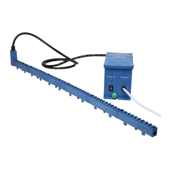
- Page 1 GPS-iMOD Installation, Operation & Maintenance Manual ® NOTICE: This product is to be used only as directed. Read entire manual before use. Do not use unless properly installed. www.globalplasmasolutions.com...
-
Page 2: Installation Location
4. End cap for each iMOD assembly bar. End cap inserts into the last modular section of the bar to prevent contamination. 5. A minimum of 2 mounting magnets per bar for securing the GPS-iMOD to the cooling coil inlet on the downstream side of the filter rack. Magnet quantity provided will increase based on overall bar length. Refer to iMod Mounting section for recommended magnet spacing. -
Page 3: Mechanical Installation
Mechanical Installation For standard applications, there should be a quantity of 1 GPS-iMOD bar assembly on each coil up to 60 inches in height. The GPS-iMOD bar(s) should be spaced a maximum of 60 inches apart for appropriate ionization coverage on the coils. - Page 4 FIGURE 4A. Please note, once the bars are assembled, there should be no “wobble” between the sections. Proceed to 2. Step 1B – Assembly of snap-type GPS-iMOD Once the mounting location has been verified, assemble the modular sections by inserting the post-end of the iMOD into the receiver-end of the first modular section already attached to the powerhead (see FIGURE 7).
- Page 5 5. When mounting the GPS-iMOD, the bottom of the GPS-iMOD should be level with top of the finned surface area of the coil as shown in FIGURE 13, with the carbon fiber brushes pointing towards the floor.
- Page 6 Connection of GPS-iMOD bars to Power Supply WARNING – The coiling or bundling of high voltage (HV) cables may cause added voltage drop and decreased ion output from the iMod. Installations where the cable(s) are touching in multiple locations will experience reduced output and lifespan.
- Page 7 CORRECT POSITION FOR THE PRIMARY POWER BEING APPLIED (See FIGURE 15). The GPS-iMOD system requires a total of 15 watts to power up to 4 GPS-iMODs at any length. The power supply will accept 24VAC, 115VAC or 208-240VAC at 50HZ or 60HZ. CAUTION!! The power supply has an internal voltage selector switch set to 115VAC from the factory, as shown in FIGURE 15.
- Page 8 RUN BOTH CABLES TOGETHER AND DO NOT ZIP TIE CONTROL WIRING TO FLEXIBLE HV CABLES! CONNECTION OF GPS-iDETECT-P 1. Remove the red jumper wire between C and NO on the GPS-iDetect-P terminal block (see FIGURE 15 for jumper wire). 2. Using 300V, 18/4, plenum rated, SHIELDED cable wire between the GPS-iDetect-P power and normally open terminals and the GPS-iMOD power supply GPS-iDetect-P terminal block as shown in FIGURE 20.
-
Page 9: Operation
1. On an annual basis, turn off power and use isopropyl alcohol and a nylon (wire free) brush to gently clean the needles. 2. Use a soft cloth with isopropyl alcohol and wipe any debris off the GPS-iMOD outer bar and spaces between needle housings. -
Page 10: Troubleshooting
If light will still not illuminate, remove power and energize after five minutes. The GPS-iMOD system uses an internal auto-reset circuit breaker. Either a voltage surge or high temperature/load condition can trip the circuit breaker. If the “Power On”... - Page 11 3101 Yorkmont Road • Suite 400 Charlotte, NC 28208 980-279-5622 © 2021 Global Plasma Solutions Inc. To access a list of applicable patents, please visit www.gpspatents.com www.globalplasmasolutions.com GPS-041-11-R4-iMOD IOM...
Need help?
Do you have a question about the GPS-iMOD and is the answer not in the manual?
Questions and answers