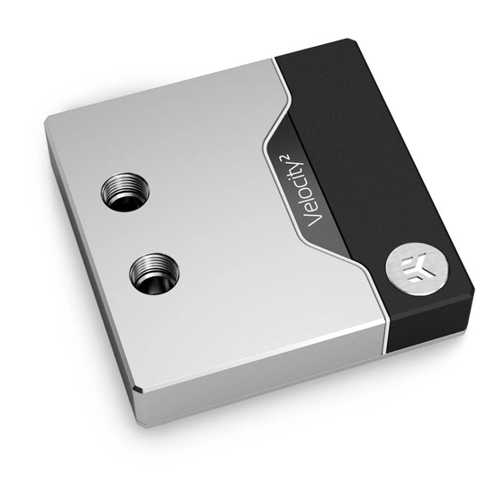
EK-Quantum Velocity2 D-RGB -LGA 1700 User Manual
Hide thumbs
Also See for Velocity2 D-RGB -LGA 1700:
- User manual (12 pages) ,
- User manual (16 pages) ,
- User manual (16 pages)
Table of Contents
Advertisement
Advertisement
Table of Contents

Summary of Contents for EK-Quantum Velocity2 D-RGB -LGA 1700
- Page 1 EK-Quantum Velocity2 D-RGB -LGA 1700 USER GUIDE...
- Page 2 This product is intended for installation only by expert users. Please consult with a qualified technician for installation. Improper installation may result in damage to your equipment. EK Water Blocks assumes no liability whatsoever, expressed or implied, for the use of these products, nor their installation.
-
Page 3: Table Of Contents
TABLE OF CONTENTS GENERAL INFORMATION ON WATER BLOCK COMPATIBILITY BOX CONTENTS WATER BLOCK DIMENSIONS TECHNICAL SPECIFICATIONS AND WATER BLOCK PARTS NICKEL PLEXI NICKEL ACETAL COPPER ACETAL FULL NICKEL SATIN TITANIUM PREPARING THE MOTHERBOARD INSTALLING THE WATER BLOCK CONNECTING THE D-RGB LED STRIP SUPPORT AND SERVICE SOCIAL MEDIA - 3 -... -
Page 4: General Information On Water Block Compatibility
- Intel LGA-1700 BOX CONTENTS Mounting Mechanism – You may not need all the screws, mounting mechanism is universal! Allen Key 2 mm (1 pc) Allen Key 2.5 mm (1 pc) EK-Quantum Velocity2 D-RGB 1700 Thermal grease (1 pc) - 4 -... -
Page 5: Water Block Dimensions
WATER BLOCK DIMENSIONS CPU WB: 94.5 mm 20.5 mm 15.3 mm 33 mm Backplate: 78 mm 9 mm 3.5 mm - 5 -... -
Page 6: Technical Specifications And Water Block Parts
TECHNICAL SPECIFICATIONS AND WATER BLOCK PARTS NICKEL PLEXI Technical Specification: Dimensions (L x H x W): 94.5 x 94.5 x 33 mm D-RGB cable length: 500 mm D-RGB LED count: 14 D-RGB connector standard 3-pin (+5V, Data, Blocked, Ground Position EAN Description Quantity 104034... -
Page 7: Nickel Acetal
NICKEL ACETAL Position EAN Description Quantity 104035 Top plate - Acetal 103951 OR Set 104589 Metal plate Assembly 8201N M3x10 DIN7991 Screw 104029 Jet plate 104028 Coldplate (Nickel) 9028 M4x14 DIN7991 Screw 104586 Backplate Assembly 104051 Acetal standout 103952 Mylar sticker 103006 LED Strip 100663... -
Page 8: Copper Acetal
COPPER ACETAL Position EAN Description Quantity 104034 Top plate - plexi 103951 OR Set 104589 Metal plate Assembly 8201 M3X10 DIN7991 Screw 104029 Jet plate 104027 Coldplate 8207 M4X14 DIN7991 Screw 104586 Backplate Assembly 104050 Acetal standout 103952 Mylar sticker 103006 LED Strip 100663... -
Page 9: Full Nickel
FULL NICKEL Position EAN Description Quantity 104037 Top plate - Nickel 103951 OR Set 104589 Metal plate Assembly 8201N M3X10 DIN7991 Screw 104029 Jet plate 104028 Coldplate (Nickel) 9028 M4X14 DIN7991 Screw 104586 Backplate Assembly 104051 Acetal standout 103952 Mylar sticker 103006 LED Strip 100663... -
Page 10: Satin Titanium
SATIN TITANIUM Position EAN Description Quantity 104405 Top plate - Nickel 103951 OR Set 104589 Metal plate Assembly 8201N M3X10 DIN7991 Screw 104029 Jet plate 104028 Coldplate (Nickel) 9028 M4X14 DIN7991 Screw 104586 Backplate Assembly 104051 Acetal standout 103952 Mylar sticker 103006 LED Strip 100663... -
Page 11: Preparing The Motherboard
PREPARING THE MOTHERBOARD STEP 1 If already installed, please remove the motherboard from your computer and place it on an even surface. Non-abrasive Cloth STEP 2 Cleaning the CPU: Wipe the IHS clean using a non-abrasive cloth or Q-tip as shown in the illustration. STEP 2 STEP 3 Applying thermal compound: Once clean, apply a line of Thermal... -
Page 12: Installing The Water Block
INSTALLING THE WATER BLOCK STEP 1 Unscrew the pre-installed backplate from the backside of the CPU using an Allen Key 2.5 mm and save it for the later steps. STEP 1 STEP 2 Before placing the water block, it is mandatory to remove the protective foil from the backside. - Page 13 STEP 3 Position the CPU Water Block onto the Motherboard. Make sure to align the holes (as shown in the picture). Make sure to double check the layer of the Thermal Grease before placing the water block onto the motherboard. STEP 3 STEP 4 After placing the water block, the stored backplate must be attached...
-
Page 14: Connecting The D-Rgb Led Strip
STEP 5 With EK-Velocity2 series water blocks, it is mandatory to use the bottom port as the INLET. Mixing the ports may result in poor thermal performance of the water block. OUTLET PORT Tighten the fittings in clockwise direction until the gasket underneath is compressed. -
Page 15: Support And Service
SUPPORT AND SERVICE In case you need assistance or wish to order spare parts or a new mounting mechanism, please contact: https://www.ekwb.com/customer-support/ For spare parts orders, refer to the page with “TECHNICAL SPECIFICATIONS AND WATER BLOCK PARTS” where you can find the EAN number of each part you might need.


Need help?
Do you have a question about the Velocity2 D-RGB -LGA 1700 and is the answer not in the manual?
Questions and answers