Table of Contents
Advertisement
OPERATING AND MAINTENANCE MANUAL
Section 1
a)
Operating and Maintenance Text
Section 2
a)
General Arrangement Drawing ................................................................................... 82967
b)
Wiring Diagram 115 /1/ 50/60 ..................................................................................... 50187
c)
Wiring Diagram 208-240 /1/ 50/60 .............................................................................. 50188
Section 3
a)
Replacing Fusible Links
b)
Humidistat Field Connections ..................................................................................... 26992
c)
Blastgate Installation Instructions ............................................................................... 27110
d)
Recommended Spare Parts List (HC-150I) ................................................................ 21237
e)
Recommended Spare Parts List (HC-150R) ............................................................... 21238
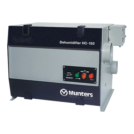
MODEL: HC-150 / DEW-150
2014-05-30
Advertisement
Table of Contents

Related Manuals for Munters HC-150


Summary of Contents for Munters HC-150
- Page 1 OPERATING AND MAINTENANCE MANUAL MODEL: HC-150 / DEW-150 Section 1 Operating and Maintenance Text Section 2 General Arrangement Drawing ................... 82967 Wiring Diagram 115 /1/ 50/60 ..................50187 Wiring Diagram 208-240 /1/ 50/60 ................50188 Section 3 Replacing Fusible Links Humidistat Field Connections ..................
- Page 2 OPERATING AND MAINTENANCE MANUAL MODEL HC-150 DEHUMIDIFIER Rev. 6.0 3/14...
-
Page 3: Table Of Contents
Front View, Cover Open ................1–4 Fig. 3–1 HC-150 Installed in Process Space ............3–1 Fig. 3–2 HC-150 Installed outside of Process Space ..........3–2 Fig. 3–3 HC-150 Installed with Existing Air-Handling Unit........3–3 Fig. 3–4 Do Not Install HC-150 This Way ..............3–4... -
Page 4: Section 1 - Introduction
1 – INTRODUCTION Your HC-150 dehumidifier is durable, simple to operate, and needs very little mainte- nance. The HC-150 can give you years of trouble-free service if you follow the recom- mendations listed in this manual. We strongly recommended that you read this whole manual. This should not take very long. -
Page 5: About The Hc-150
Let’s say that you want to dry the air in a storage room, using the HC-150. Damp “pro- cess” air is pulled into the unit from the storage room. The desiccant in the Honey- ® Combe wheel picks up most of the moisture in the air. Once it has been “dried out,” the process air is vented back into the storage room. -
Page 6: Controls And Indicators
Temperature sensors • Electric heating elements for the reactivation air Figures 1–3 and 1–4 show some additional parts on the HC-150 unit. The Honey- Combe ® wheel is turned by a small drive motor and a toothed belt. A spring-type tensioner automatically adjusts the belt tension. - Page 7 The control system uses a number of sensors and controllers to supervise the activity of the HC-150. On the model HC-150I only, a Solid State Power Controller (SSP1) turns the heating elements on and off. This controller responds to a signal from a temperature sensor (TSE1) which is located in the reactivation air stream after the wheel.
-
Page 8: Protective Circuits
The wiring for each heating element includes a fusible link. This link will open if the element overheats. If this happens, the HC-150 will continue to operate, but will not dehumidify the process air. To correct this, find the cause of the overheat condition and replace the fusible link. - Page 9 1–6...
-
Page 10: Section 2 - Safety Notes
Munters is concerned about the safety of anyone who uses or services the HC-150 unit. Some of the parts inside the HC-150 can be dangerous if an untrained person tries to service the unit. Throughout this manual, we have pointed out some of the hazards which may occur in the use of the HC-150. - Page 11 The two blowers inside the HC-150 spin very quickly. Your hand may be hurt if you put it inside a blower while it is turning. Keep your hands away from the blowers while the unit is turned on. Do not run the HC- 150 unless both the process and reactivation fans are protected by ductwork or finger guards.
-
Page 12: Section 3 - Installation And Startup
Reactivation air IN – from outdoors OUTDOORS PROCESS SPACE (STORAGE AREA) Damper HC-150 DEHUMIDIFIER Damper HUMIDISTAT (option) Process air OUT – Process air IN – to process space from process space J136 FIGURE 3–1 HC-150 INSTALLED IN PROCESS SPACE 3–1... - Page 13 7" space in front of the reactivation air intake to allow smooth air flow (not necessary if ductwork is installed) Figures 3–1, 3–2 and 3–3 show three different ways of installing the HC-150. There are some simple rules for arranging the ductwork for the HC-150: Process air intake ....
- Page 14 5 feet. Allow the same distance between the inlet and outlet for the reactivation air. Figure 3–3 shows the set-up if you are installing the HC-150 in a system with an existing air-handling unit. Notice that both sides of the HC-150 are connected upstream of the air-handling unit.
- Page 15 POOR ARRANGEMENT Do not set up the HC-150 so it bypasses the air handling unit. The air handling unit can create back pressure. This can cause the air to flow backwards through the HC-150. HC-150 DEHUMIDIFIER HANDLING UNIT PART A...
-
Page 16: Connecting The Ductwork
HC-150, and this can overload the unit. For recommendations, consult the Service Operations Department at Munters. 3.3 CONNECTING THE DUCTWORK Don’t try to operate the unit without ductwork. The unit will not be damaged, but it will not operate correctly without the proper ductwork in place. Figures 3–1, 3–2 and 3–3 show some correct installations. -
Page 17: Connecting The Remote Humidistat
Do not mount the humidistat near the outlet vent for the process air from the HC-150. Make the wiring connections between the humidistat and the HC-150 using 24 AWG wire. - Page 18 Open the process damper a bit. Wait ten minutes before checking the reactivation outlet temperature again. If it is still above 120°F, open the process damper and wait again. Continue doing this until you find the setting which causes the reactiva- tion temperature to drop to 120°F.
-
Page 19: Section 4 - Preventive Maintenance
The HC-150 unit requires very little regular maintenance. Check these points every 30 days: 4.1 CLEAN THE AIR FILTERS The HC-150 unit includes two air filters. These are shown in Fig. 1–4. Each filter is made of expanded aluminum, mounted in a metal frame. -
Page 20: Section 5 - Troubleshooting
5.1 POSSIBLE TROUBLE CONDITIONS In order to check most of these trouble conditions, the HC-150 must be turned on and operating, or trying to operate. Some units are wired with remote humidistats. With this type of set-up, it is sometimes not clear whether the humidistat is trying to turn on the HC-150. -
Page 21: Reactivation Outlet Temperature Is Too Low
HC-150. The temperature may be too low if you try to operate the HC-150 without any ductwork. This can allow too much process air through the unit. Install a damper downstream of the process outlet. -
Page 22: Poor Dehumidifying Performance
A low outlet temperature can also be caused by a problem with the reactivation blower. Turn off the HC-150 and try to spin the blower by hand. It should turn freely. Model HC-150I only – There may be a problem with the overheat anticipator sensor (TS03). -
Page 23: Checking The Heating Elements
5.7 CHECKING THE HEATING ELEMENTS This service procedure involves an electrical hazard. Service work should only be done by an electrician who has been qualified by Munters. The heating elements are located near the intake for the reactivation air. See Fig. 1–4. -
Page 24: Checking The Humidistat
You should see 0 Volts across the contacts. You can also check the wiring between the humidistat and the HC-150. The humi- distat is connected to terminals on the printed circuit board. When the humidistat is not calling for dehumidification, you should see 24 VAC across the contacts. -
Page 25: Suggested Replacement Parts
This will permanently damage the wheel. 11. If the wheel is still plugged, or if the honeycomb structure has softened, please call the Service Operations Department at Munters. 12. To replace the wheel, reverse Steps 2 through 6 above. - Page 27 Munters Corporation 79 Monroe Street, P.O. Box 640 Amesbury, MA 01913–0640 TEL: (978) 241-1100 or (800) 843-5360 FAX: (978) 241-1217 WWW: http://www.muntersamerica.com e-mail: dhinfo@munters.com...
- Page 31 Replacing Fusible Links Revision 7/11...
- Page 32 9. REMOVE INSULATED MALE SPADE TERMINAL FROM THE INSULATED FEMALE SPATE ATTACHED TO THE WHITE WIRE. 10. ASSEMBLE NEW FUSE SUB ASSEMBLY. CRIMP THE NON INSULATED FEMALE TERMINALS TO BOTH SIDES OF THE FUSE. 11. REMOVE FUSE ASSEMBLY FROM HEATER BY PULLING STRAIGHT OUT ON THE UNINSULATED FEMALE TERMINALS.
- Page 33 HC-150 and HC-300 Humidistat Field Connections HUMIDISTAT (VICONICS) HSP1 Input Plug All Dashed Wiring by others HC-150 / 300 HSP1 Input Plug Regin Humidistat p/n 90485-xx HUMIDISTAT HSP1 Input Plug Regin All Dashed Wiring by others 26992, Rev. 2, 10/10/2013...
- Page 34 H200 Direct Connect to HC-150/300 Circuit Board HUMIDISTAT (VICONICS) Board Ground lug or mounting post PCB1 All Dashed Wiring by others Main Unit Circuit Board HUMIDISTAT (ROTRONICS SF-D65) HSP1 Input Plug All Dashed Wiring by others 26992, Rev. 2, 10/10/2013...
- Page 36 DESICCANT SUPPORT 15985 HEATERS 208V-230V 91761-03 FUSES 1 AMP/250 VOLT 3 AMP/250 VOLT FNM 10 AMP/250 VOLT 92012-33 MUNTERS DH PH. (978) 241-1100 FAX (978) 241-1214 PH. (800) 843-5360 DRIVE MOTOR WAS 92054-02 02/05/04 ADDED FUSES 12/04/97 DESCRIPTION DATE REVISIONS...
- Page 37 PROCESS IN 95007-32 REACT IN 95007-39 ROLLERS DESICCANT SUPPORT 15985 HEATERS 115V 91761-14 MUNTERS DH PH. (978) 241-1100 FAX (978) 241-1214 PH. (800) 843-5360 DRIVE KIT WAS 43579-01, HEATER WAS 91761-07 02/05/04 DRIVE MOTOR WAS 92054-01 01/15/04 DESCRIPTION DATE REVISIONS...
Need help?
Do you have a question about the HC-150 and is the answer not in the manual?
Questions and answers