Table of Contents
Advertisement
Operator's Manual
Maintenance Manual,
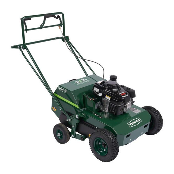
TurnAer
Product Number 85397 Briggs and Stratton Powered
Product Number 85398 Subaru Powered
DANGER -
IF INCORRECTLY USED THIS MACHINE CAN CAUSE SEVERE INJURY.
THOSE WHO USE AND MAINTAIN THIS MACHINE SHOULD BE TRAINED IN ITS
PROPER USE, WARNED OF ITS DANGERS, AND SHOULD READ THE ENTIRE MANUAL
BEFORE ATTEMPTING TO SET-UP, OPERATE, OR SERVICE THE MACHINE.
1655 101st Avenue NE ● Minneapolis, Minnesota 55449-4420 USA
Phone (763) 785-1000 ● FAX (763) 785-0556
and
Parts Lists
TURFCO
XT5
™
Starting Serial Number R00301
And
Starting Serial Number T00701
US Patent 6,708,773
Additional Patents Pending
Manual Number 668268 Rev F
TURFCO MFG., INC.
2013 Turfco Mfg., Inc.
®
Aerator
™
Advertisement
Table of Contents

Subscribe to Our Youtube Channel
Related Manuals for TURFCO TurnAer XT5


Summary of Contents for TURFCO TurnAer XT5
- Page 1 PROPER USE, WARNED OF ITS DANGERS, AND SHOULD READ THE ENTIRE MANUAL BEFORE ATTEMPTING TO SET-UP, OPERATE, OR SERVICE THE MACHINE. TURFCO MFG., INC. 1655 101st Avenue NE ● Minneapolis, Minnesota 55449-4420 USA Phone (763) 785-1000 ● FAX (763) 785-0556 2013 Turfco Mfg., Inc.
-
Page 2: Table Of Contents
Product Records IMPORTANT: Record the information from the serial number plate of your XT5 Aerator. It will be necessary to furnish your Model Designation, Product Number, and Serial Number when ordering parts. TurnAer XT5 Aerator Model Designation Product Number Serial Number... -
Page 3: Specifications
SPECIFICATIONS Specifications Intended Use: The TurnAer XT5 Aerator is a self-propelled tine type aerator. The XT5 Aerator is intended to be used for the aeration of the turf at a properly prepared worksite. The XT5 Aerator is NOT intended to be used for any purpose other than the aeration of turf. The XT5 Aerator is NOT designed for or intended to accept riders. -
Page 4: Recognizing Safety Warnings And General Safety Practices
SAFETY Recognizing Safety Warnings Used In Manual LOOK FOR THE SAFETY HAZARD WARNING SYMBOL The symbol is used to alert the operator of safety hazards. It is used in conjunction with the words DANGER, WARNING, and CAUTION. DANGER WARNING CAUTION “DANGER”... - Page 5 SAFETY ● Beware of slippery conditions. Wet turf can be ● Pull the starter cord slowly until resistance is felt. encountered on slopes, when turning or stopping, or Then pull the cord rapidly to avoid kickback and to at higher speeds. prevent hand or arm injury.
-
Page 6: Assembly And Setup
ASSEMBLY Assembly and Setup (See Figure 1) SAFETY FIRST bushing goes through the hole in the lift arm and the wheel arm and is held in place by the flat washers. (See Figure 1). Tighten securely. Check movement WARNING of the transport wheels lift handle. TO AVOID SERIOUS INJURY, Step 6. - Page 7 ASSEMBLY SCREW 3/8”-16 x 1-1/4” 3/8”-16 x 1” FLAT HEX HEAD SCREW CARRIAGE WASHERS WITH FLAT WASHERS, BOLT WITH BUSHING AND 3/8”-16 3/8”-16 NYLOCK NUT BUSHING NYLOCK NUT NYLOCK NUT TRANSPORT LOCKING PIN IN “UNLOCKED” POSITION LIFT TUBE HANDLEBAR BASE Unleaded CHECK OIL Gasoline...
-
Page 8: Description
DESCRIPTION Description INTENDED USE AND FUNCTION WARNING The XT5 Aerator is a self-propelled coring tine TO AVOID SERIOUS INJURY, type aerator. The XT5 Aerator is intended to be Move To the Operator’s Position Behind The Handlebar used for the aeration of the turf at a properly Before Engaging Any Operator Controls prepared worksite. - Page 9 DESCRIPTION PUSH DIRECTION HANDLE FORWARD Engine Controls: All engine controls are on the engine. TO GO FORWARD ● On the Briggs & Stratton engine, a throttle is located on the right hand side of the engine. The throttle controls the engine speed and has a shut down “Stop”...
-
Page 10: Operation
OPERATION Operation PRE-OPERATION CHECK LIST WARNING Safety First TO AVOID SERIOUS INJURY, Wear the appropriate safety gear. Hearing Read and Understand the Entire NEUTRAL protection, gloves and safety shoes are strongly Operator’s Manual Before Operating This PULL TO UNLOCK DRIVE WHEELS recommended during operation. -
Page 11: Maximum Angle Of Operation
OPERATION OPERATING DIRECTION CONTROL HANDLE the removable weight in the center pocket in the top cover on the chassis. During operation, slight downward Slowly push the direction handle forward to engage pressure can be applied to the handlebars to increase the forward direction. -
Page 12: Planning Aerating Path
OPERATION FORWARD REVERSE TRANSPORT AERATE TINES UP TINES DOWN 15° Max. PLANNING AERATING PATH tight spot. While backing up, pull on the handlebar in the direction you want to turn to swing the machine Move the XT5 to the area being aerated before around. -
Page 13: Decals
TINES UP TINES DOWN 15° Max. NEUTRAL STOP PULL TO UNLOCK DRIVE WHEELS CHECK OIL WITH ENGINE SITTING LEVEL Turfco TurnAer XT5 Aerator ® Product Number 85397 - US Patent 6,708,773 Additional Patents Pending 5 Km/h A. DASHBOARD OPERATING INSTRUCTIONS DECAL (3.5 MPH) -
Page 14: Operator Daily Inspection
SERVICE Operator Daily Inspection Troubleshooting Table WARNING PROBLEM POSSIBLE CAUSE TO AVOID SERIOUS INJURY, Worn Drive Train Bearings or Excessive Vibration Never Perform Any Inspection With the Chain Idler Bearings. Worn or Noise Aerator Engine Running. Or Misadjusted Drive Chains. SAFE-24A Wear the appropriate safety gear when Loose Components. -
Page 15: Service And Adjustment
SERVICE Service and Adjustments WARNING TO AVOID SERIOUS INJURY, Never Perform Any Service or Adjustment Procedures With the Engine Operating. All Of The Following Lubrication, Service, or Adjustment Procedures Involve Or Are Near Rotating and Moving Parts. Use Caution When Working Near the Tine Reel Assembly. Tines Are Sharp and Can Easily Cut Hands and Feet. -
Page 16: Transaxle V-Belt Adjustment
SERVICE TRANSAXLE V-BELT ADJUSTMENT (See Figure 6) V-BELT IDLER PULLEY ENGINE The transaxle is driven by a V-belt from the engine. V-BELT PULLEY Tension on the V-belt is maintained by an idler pulley that is mounted to the deck. The idler can be adjusted to set the V-belt tension. -
Page 17: Chain Idler Sprocket Adjustments
SERVICE CHAIN IDLER SPROCKET ADJUSTMENT (See Figure 8) The chain idler sprockets (one per side - located under the side chain guards) can be adjusted to remove excess slack in the chain caused by normal chain wear or stretch. Before adjusting idler sprocket position, ensure that the chain and all sprockets have been cleaned and that the chain seats properly on the sprockets.
Need help?
Do you have a question about the TurnAer XT5 and is the answer not in the manual?
Questions and answers