Tecnam P2008 JC Flight Manual
Hide thumbs
Also See for P2008 JC:
- Flight manual (265 pages) ,
- Aircraft flight manual (200 pages) ,
- Flight manual (83 pages)
Advertisement
Quick Links
Li
0
D
0
0
0
D
0
MANUFACl1JRER:
0
AIRCRAFT MODEL:
EASA
TYPECERTIFICATENR.:
0
SERIAL NUMBER:
BUILD YEAR:
D
REGISTRATION MARKINGS:
This Aircra ft Flight Manual is approved and applies only to EASA CS-VLA certified
airp/anes.
D
This Manual must be carried in the airplane at all times.
This aeroplane has to be operated in compliance with procedures and lfmilalions contained
herein.
D
Costruzioni Aeronautiche TECNAM srl
Via Maiorise
CAPUA ( CE)
Tel. +39-0823 997538
WEB:
www . tecnam.com
D
D
Aircraft Flight Manual
Doc. No. 20081100
Ed. 2-Rev. 1
2018, March J2 1h
TECNAM P2008 JC
C. A. TECNAM S.r.I.
P2008JC
A . 583 (DATED 2013, 27 SEPTEMBER}
..
...
cAJ.1.8..
......
lj
-
Italy
...........
.
.
. . ......... .
.
.
.
Advertisement

Related Manuals for Tecnam P2008 JC


Summary of Contents for Tecnam P2008 JC
- Page 1 Aircraft Flight Manual Doc. No. 20081100 Ed. 2-Rev. 1 2018, March J2 1h TECNAM P2008 JC C. A. TECNAM S.r.I. MANUFACl1JRER: P2008JC AIRCRAFT MODEL: EASA TYPECERTIFICATENR.: A . 583 (DATED 2013, 27 SEPTEMBER} ... SERIAL NUMBER: cAJ.1.8....
- Page 2 SECTION I NDEX RECORD O F REVISIONS ..................LIST OF EFFECTIVE PAGES ..................FOREWORD ......................SECTIONS LIST ...................... Ed. 2, Rev. 0 Aircraft Flight Manual INDEX...
-
Page 3: Record Of Revisions
RECORD OF REVISIONS Any revision to the present Manual, except actual weighing data, is recorded: a Record of Revisions is provided in this Section and the operator is advised to make sure that the record is kept up-to-date. The Manual issue is identified by Edition and Revision codes reported on each page, lower right side. - Page 4 EASA Approval or Tecnam Approval Revised tDescription of Under DO A page R evision Erivileges Approved under the authority of DOA, Editorial revision. A. Sabino Caruso M.Oliva ref. EASA.2 IJ.335 0- 1 ,4,7 Cover, RoR and LOEP updated. Airspeed indicator markings amended;...
- Page 5 INTENTIONALLY LEFT BLANK Ed. 2, Rev. Aircraft Flight Manual...
- Page 6 INTENTIONALLY LEFT BLANK 2, Rev. 0 Aircraft Flight Manual...
-
Page 7: List Of Effective
LIST OF EFFECTIVE PAGES The List of Effective Pages (LOEP), applicable to manuals of every operator, lists all the basic AFM pages: each manual could contain either basic pages or one variant of these pages when the pages of some Supplements are embodied. Pages affected by the current revision are indicated by an asterisk (*) following the re... - Page 8 INTENTIONALLY LEFT BLANK Ed. 2, Rev. 0 Aircraft Flight Manual...
-
Page 9: Foreword
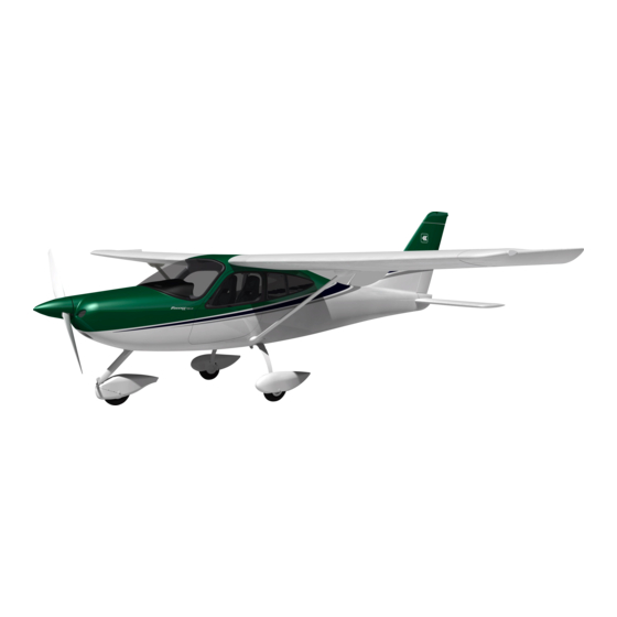
FOREWORD Tecnam P2008 JC is a single-engine two-seat aircraft with a strut braced high wing and fixed landing gear. Section I provides general information and it contains definitions, symbols explana tions, acronyms and terminology used. Before using the airplane, you are recommended to read carefully this manual: a deep knowledge of airplane features and limitations will allow you for operating the airplane safely. -
Page 10: Sections List
SECTIONS LIST Section General (*) Section 2 Limitations (**) Section 3 Emergency Procedures (**) Section 4 Normal Procedures (**) Section 5 Performance (***) Section 6 Weight and balance (*) Section 7 Airframe and Systems description (*) Section 8 Ground Handling and Service (*) Section 9 AFM Supplements list (*) (*) non-approved Sect ion... - Page 11 SECTION 1 - GENERAL o· I NDEX INTRODUCTION ....................3 CERTIFICATION BASIS .................. WARNINGS - CAUTIONS - NOTES ..............THREE-VIEW AND DIMENSIONS ................ ENGINE ....................... PROPELLER ................... FLIGHT CONTROL SURFACES TRAVEL .............. 7 SPECIFIC LOADINGS ...................
- Page 12 � 00&1ll &ll ll'©li'& 10 0 � mNIM � JJ© !¥ 0 � Pagel- 2 rNTENTIONALL Y LEFT BLANK Ed. 2, Section 1 General...
- Page 13 Page l - 3 I NTRODUCTION The Flight Manual has been prepared to provide pilots and instructors with in formation for the safe and efficient operation of this very light airplane. This manual includes the material required to be furnished to the pilot of CS VLA.
- Page 14 THREE-VIEW AND DIMENSIONS Figure General v iews Ed. 2, Section 1 General THREE·VIEW AND DIMENSIONS...
- Page 15 Dimensions Wing 9.00 (29 .5 ft) Wing Span fi2) Wing Area 12 .16 (130.9 6. 7 Aspect Ratio Teper Ratio Wing chord 1.373 (4.5 ft) Fuselage Overall length 6.93 (22.9 ft) Overall w idth 1.2 0 m 9 ft) Overall height 2.67 m (8.8 ft) Empennage Stabilator span...
- Page 16 MTV-34 Propeller for aircraft with MTOW Increment at 650 kg AFMS 59 !? O n@� � l!ll@ O &H� � dJ@ Page MTl- 6 ENGINE Bombardier-Rotax GmbH Manufacturer 912 S 2 Model 4 cylinders horizontally opposed with Engine type 135 2 c.c. of overall displacement, liquid cooled cylinder heads, ram-air cooled cylinders, two carburetors, integrated re...
- Page 17 MTV-34 MTOW Propeller for aircraft with Increment at 650 kg AFMS 59 &ll ll'© d [¥0n @IIDQ [iVillil!Jil {]!]@ U � dl@ Page Mn- 1 FLIGHT CONTROL SURFACES TRAVEL (± A ilerons Up 22° Down 14 ° 2°) (± Stabilator (refer to Trailing Edge) Up 4°...
- Page 18 Page l - 8 ACRONYMS AND TERMINOLOGY Calibrated Airspeed is the indicated airspeed expressed in knots, KCAS corrected taking into account the errors related to the instrument itself and its installation. Indicated Airspeed is the speed shown on the airspeed indicator KIAS and it is expressed in knots.
- Page 19 Page l-9 Meteorological terminology International Standard Atmosphere: is the air atmospheric standard condition at sea level, at 15°C (59°F) and at 1 0 1 3.25hPa (29.92inHg). Official atmospheric pressure at aimort leyel: it indicates the air craft absolute altitude with respect to the official airport level. Theoretical atmospheric pressure at sea level: is the atmospheric pressure reported at the medium sea level, through the standard air pressure-altitude relationship, starting from the airport QFE.
- Page 20 Page I Aircraft performance and flight planning terminology Crosswind Velocity is the velocity of the crosswind component for the which adequate control of the air plane during takeoff and landing is assured. Usable f uel is the fuel available for flight planning.
- Page 21 Page l- I I Weight and balance terminology Datum "Ref erence datum" is an imaginary vertical plane from which all horizontal distances are measured for balance purposes. is the horizontal distance of an item meas ured from the reference datum. Moment is the product of the weight of an item multiplied by its arm.
- Page 22 &II � �T'EcNIM � JJ@ !?U � �00@ 0 Page INTENTIONALLY LEFT BLANK Rev 0 Section 1 General...
- Page 23 Page • 10. UNIT CONVERSION CHART TEMPERATURE 9·(F-32) [ • F] [ " CJ Celsius Fahrenheit (�·c)+n [ " F] ["CJ Fahrenheit Celsius FORCES Kilograms [kg] 2.205 Pounds [lbs] [ k g] Pounds [lbs] 0 4536 Kilograms SPEED [ m/ s] Meters per second 196.86 Feet per minute...
- Page 24 1 1 . LITRES US GALLONS CONVERSION CHART US Galllin.s US•Gallilns 11.4 15.1 22.7 30.3 37.9 10.6 45.4 11.9 53.0 60.6 13.2 68.1 15.9 18.5 75.7 83.3 21.1 23.8 90.9 26.4 98.4 29.1 106.0 31.7 113.6 34.3 121.1 37.7 128.7 39.6 136.3 42.3...
- Page 25 SECTION 2 LIMITATIONS INDEX INTRODUCTION ••••••••••••••••••••••••••••••••••••••••••••••••••••••••••••••••••••••••••••••••••••••• AIRSPEED LIMITATIONS •••••••••••••••••••••••••••••••••••••••••••••••••••••••••••••••••••••••••• AIRSPEED INDICATOR MARKINGS •••••••••••••••••••••••••••••••••••••••••••••••••••••••••• POWERPLANT LIMITATIONS ........... FUEL ••••••••••••••••••••••••••••••••••••••••••••••••••••••••••••••••••••••••••••••••••••••••••••••••••••••••• LUBRICANT •••••••••••••••••••••••••••••••••••••••••••••••••••••••••••••••••••••••••••••••••••••••••••••• COOLANT LIQUID ••••••••••••••••••••••••••••••••••••••••••••••••••••••••••••••••••••••••••••••••••••• PAINT ••••••••••••••••••••••••••••••••••••••••••••••••••••••••••••••••••••••••••••••••••••••••••••••••••••••• PROPELLER •••••••••••••••••••••••••••••••••••••••••••••••••••••••••••••••••••••••••••••••••••••••••••••• 10. MAXIMUM OPERATING ALTITUDE •••••••••••••••••••••••••••••••••••••••••••••••••••••••••• 1 1 . AMBIENT TEMPERATURE ••••••••••••••••••••••••••••••••••••••••••••••••••••••••••••••••••••••••...
- Page 26 INTENTIONALLY LEFT BLANK Ed. 2, Rev. 0 Section 2 Limitations...
- Page 27 I NTRODUCTION Section 2 includes operating limitations, instrument markings, and basic placards necessary for saf e operation of the aeroplane, its engine, standard systems and standard equipment. Ed. 2, Rev. 0 Section 2 - Limitations INTRODUCTION...
- Page 28 INTENTIONALLY LEFT BLANK Ed. 2, Rev. 0 Section 2 Limitations...
- Page 29 MTV-34 Propeller for aircraft with MTOW Increment at 650 kg AFMS 59 !? O n@ � &11 11'©1J'& lO O �TECNAM � dJ@ Page MT2-5 2. AIRSPEED LIMITATIONS The following table addresses the airspeed limitations and their operational signif icance:...
- Page 30 AFMS 59 MTV-34 Propeller for aircraft with MTOW Increment at 650 kg c.\ll lf©lra.l OO � c!J@ �fiiENAM � On@� ll"iJ @ !iil l\!m O Page MT2-6 3. AIRSPEED I NDI CATOR MARKINGS Airspeed indicator markings and their colour code are explained in the following table.
- Page 31 &H!J'©ln110 0 �@XQ)@ � miiiM l? D � �U!1&111 Page 2 POWERPLANT LI MITATIONS Following table reports the powerplant operating limitations: ENGINE MANUFACTURER: Bombardier Rotax GmbH. ENGINE MODEL: 9 1 2 S2 MAXIMUM POWER: T ime max. Max Power Maxrpm. kW (lg)) (minutes) Prop.
- Page 32 FUEL 2 TANKS: 62 litres each one (16.38 US gallons) 1 24 litres (32. 76 US gallons) MAxIMUM CAPACITY: MAxIMUM USABLE FUEL: 1 20 litres (32 US gallons) MOGAS ASTM 048 1 4 (min RON 95/AKI 9 1 ) APPROVED FUEL: MOGAS EN 228 Super/Super plus (min.
- Page 33 MTV-34 Propeller for aircraft with MTOW Increment at 650 kg AFMS S9 &II � � dl@ !?UH @ � �@Ilil{]!)&l U �TECNAM Page MT2- 9 9. PROPELLER Manufacturer MT Propeller Mode l MTV - 34-1 - N l 70 -202...
- Page 34 12. POWERPLANT INSTRUMENTS MARKI NGS Powerplant instrument markings and their colour code significance are shown be low: REDLINE YELLOW ARC REDLINE •GREEN N orm al INSTRUMENT Minimum Caution Maximum ·limit operating l imit Propeller 577 - 2265 2265 - 2388 2388 ·c Oil temp.
- Page 35 INTENTIONALLY LEFT BLANK Ed. 2, Rev. 0 Approved Section 2 - Limitations...
- Page 36 MTV-34 Propeller for aircraft with MTOW Increment at 650 kg AFMS 59 � u;'ll H @llilQ �liil OO&l O �mNA'M � JJ@ Page MTI-1 2 14. WEIGHTS Oonaitlon Weight Maximum takeoff weight 650 kg 1433lb Maximum landing weight 650 kg 1433lb Baggage <!lompartmentl Maximum weight...
- Page 37 INTENTIONALLY LEFT BLANK Ed. 2, Rev. 0 Approved Section 2 Limitations...
- Page 38 1 5. CENTER OF GRAVITY RANGE Datum Vertical plane tangent to the propeller flange (the aircraft must be levelled in the longitudinal plane) Levelling Refer to the seat track supporting beams (see procedure in Section 6) Forward limit 1 . 84 1 m ( 20 % MAC) aft of datum for all weights Aft limit 1 .978 m (30 % MAC) aft of datum for all weights The pilot is responsible f or ensuring that the airplane is...
- Page 39 rNTENTJONALL LEFT BLANK Ed. 2, Rev. Approved Section 2 - Limitations...
- Page 40 MTV-34 Propeller for aircraft with MTOW Increment at 650 kg AFMS S9 Ui'DH@ lluQ �m lffil D � dl© � TEcNAM Page MT2 - 1 6 1 6. APPROVED MANOEUVRES The aircraft is certified in Normal Category in accordance with EASA CS - VLA regu...
- Page 41 MTV-34 Propeller for aircraft with MTOW Increment at 650 kg AFMS 59 Ui Dll@� liYil@oo l! !J&il l � JJ @ � �TECNAM Page MTI - 1 7 MANOEUVRES LOAD FACTOR LIMITS 1 7. Manoeuvre load factors limits are as follows:...
- Page 42 18. DEMONSTRATED CROSS WIND SAFE OPERATIONS The aircraft controllability, during take-offs and landings, has been demonstrated with a cross wind components of l 5kts. 19. FLIGHT CREW Minimum crew: I pilot Maximum number of occupants: people (including the pilot) 2, Rev. 0 Approved Section 2 Limitations...
- Page 43 AFMS SB - MD302 and G3X Touch Page M 2- 1 9 20. KINDS OF OPERATION EQUIPMENT LIST (KOEL) This paragraph reports the KOEL table, concerning the equipment list required on board under CS-VLA regulations to allow flight operations in VFR Day and VFR Night.
- Page 44 AFMS SB - MD302 and G3X Touch Page M2-20 VFR Day Equipment VFR Night MD302 (PFI) MAGNETIC DIRECTION INDICATOR • • FUEL ANALOGUE QUANTITY INDICATORS ANALOGUE CT CHT if applicable) • • INDICATOR ANALOGUE RPM INDICATOR • • • ANALOGUE OIL TEMPERATURE INDICATOR •...
- Page 45 MTV-34 Propeller for aircraft with MTOW Increment at 650 kg AFMS 59 [?'fl�� IMJ@o o ll ll&il l &II � �TECNAM � c!J@ Page MTN2- 21 LIMITATIONS PLACARDS The following limitation placards are placed in plain view on the pilot, reminding the observance of aircraft operating limitations according to installed equipment configuration (see KOEL, Para.
- Page 46 AFMS SB - MD302 and G3X Touch � .JJ@ LSll ll@liJ{t lMltilmmil lJ E«J'fiC'iiiM � Page M 2-22 Below the G3X Touch LH screen, the following label is placed: FOR S I TUATIONAL AWA R E N ESS O N LY Ed.
- Page 47 � OTHER PLACARDS Engine compartment placards OILTANK ClllCIC LD!I. :JO NOT P1.T WITtt 0.. LEVE.L. OUT O< UUITE COOLANT OVERFLOW BOTILE KEEP LEVEL BETWEEN MINIMUM AND MAXIMUM Oil brakes reservoir placard Ed. 2, Rev. 0 Approved Section 2 Limitations OTHER placards...
- Page 48 Usable fuel markings R i g ht Ta n k Left Ta n k U s a b l e F u e l U s a b l e F u e l 6 0 l itres 6 0 l itres Allowed fuel placard MOGAS ASTM 04814...
- Page 49 AFMS for NIGHT equipped airplanes &II � �- �@ [? UH@ � 11&1IJilll1 1&1 U Pa g e 2N - 25 Throttle marking Fuel sele ctor valve marking 1\\) ..Choke placard Alternate static port placard Ed. 2, Rev. 0 Approved Section 2 Limitations...
- Page 50 AFMS VFR NIGHT equipped airplanes &ll li'©U'fi il l �- !¥ 0 0@ � IMJ&11Jil rnm D Page 2N - 26 Cabin heat/defrost placard -, . DEFROST AND CABIN HEAT Carb heat placard Ignition key placard Master/Generator placards Map-light placard •...
- Page 51 Flap indicator placard FLAP · ® Backrest lever placard BACKREST: P RESS TO U N LOCK Safety equipment location placard F I RST AID KIT F I R E EXTI N G U I S H E R are i n the l u ggage compartment Elt placard Battery placard...
- Page 52 AFMS SB - MD302 and G3X Touch Page M 2-28 Upper panel 111 1 10 A N N U N C IATOR PAN E L ____ Switches labels b][:J � . [:J " PITOT LANDING A VIONIC UGHT UGHT MASTER HEAT Door lock lever C LOSED...
- Page 53 INTENTIONALLY LEFT BLANK Ed. 2, Rev. Approved Section 2 Limitations OTHER placards...
- Page 54 INTENTIONALLY LEFT BLANK 2, Rev. 0 Approved Section 2 Limitations placards OTHER...
- Page 55 AFMS for VFR NIGHT equipped airplanes lfDH @ � !Mlm w &ll � Page 3N SECTION EMERGENCY PROCEDURES I NDEX INTRODUCTION ............
- Page 56 INTENTIONALLY LEFT BLANK 2, Rev. 0 Section Emergency procedures INDEX...
- Page 57 INTRODUCTION Section 3 includes checklists and detailed procedures to be used in the event of emergencies. Emergencies caused by a malfunction of the aircraft or engine are extremely rare if appropriate maintenance and pre-flight inspections are carried out. Before operating the aircraft, the pilot should become thoroughly familiar with the present Manual and, in particular, with the present Section.
- Page 58 AIRPLANE ALERTS The alert lights, located on the instrument panel can have the following colours: to indicate that pertinent device is turned ON to indicate no-hazard situations that have to be considered and which require a proper crew action to indicate emergency conditions Ed.
- Page 59 AFMS for VFR NIGHT equipped airplanes f? O ll@ � &!! � lMlooaiJ 00&1 1] � TECNAM �@ Page JN 2.1 . ELECTRIC POWER SYSTl!M MALFUNCTION Alternator Failure Light Alternator light may illuminate f or a f aulty alternator or when voltage is above J 6 V;...
- Page 60 AFMS SB - MD302 and G3X Touch � � �TEC'iiiM .JJ@ a � � Page M3-6 2.2. G3X TOUCH FAILURES In case ofLH or RH display failure, navigation and engine data will be automati cally available in the remaining display (split mode). INSTRUCTION: revert to the remaining display.
- Page 61 AFMS for VFR NIGHT equipped airplanes &II � t«J mNA'M � © !?OU @ � !Ml@Ilil l!MIDO Page JN PITOT HEATING SYSTEM F AILURE! When the Pitot Heat system is activated, the green PITOT HEAT ON saf e operating annunciation is ON; If the amber PITOT HEAT is turned ON, but the caution remains ON, the Pilot Heat system is not functioning properly.
- Page 62 AIRPLANE EVACUATION With the engine secured and propeller stopped (if practical): Parking brake: Seat belts: unstrap completely Headphones: REMOVE Door: OPEN Escape away f rom fl a mes/ hot engine compartment/ spilling f uel ta11ksl Hot brakes. ENGINE SECURING Following procedure i s applicable t o shut-down the engine in flight: Throttle Lever IDLE Ignition key...
- Page 63 AFMS 59 MTV-34 Propeller for airplanes with MTOW Increment at 650 kg � 'fiC'ii.i i &lj a'@d [?OH @ � IMJ [fil[Ji){!!]@ 0 � c!J@ Page MT3 5. ENGINE FAILURE 5.1 . ENGINE FAILURE DURING TAKE-OFF Throttle: IDLE (keep f ully out) Rudder: Keep headitlg control Brakes:...
- Page 64 AFMS for VFR NIGHT equipped airplanes &II � �mm i?a� � l!"il@IJil (! !]@ a � © Page 3N ENGINE FAILURl!S DURING FLIGHT S.3.1 Low Fuel Pressure If the fuel pressure indicator falls below 2.2 psi FP LOW warning is ON: Electric fuel pump: Fuel selector valve: select apposite f uel tank if NOT empty...
- Page 65 AFMS for VFR NIGHT equipped airplanes &H� �@ !?UH @IIDQ IMJm (J!J&l a Page JN 5.3.2 Low Oil Pressure !foil pressure is below1 2 psi OP LOW warning is ON: Throttle Lever REDUCE Minimum practical Land as soon as practical If oil pressure does not increase and OP LOW warning persists ON: Land as soon as possible applying forced landing procedure (See Para.
- Page 66 5.3.3 Hi gh Oil Temperature If OP LOW warning is ON, see para. 5.3.2 "Low Oil Pressure". If oil pressure is within l imits: Throttle Lever REDUCE Minimum practical If oil temperature does not decrease INCREASE if practical Airspeed If oil temperature does not come back within /1mits, the thermostatic valve regulating the oil flow to the heat exchangers could be damaged, or an oil leakage can be present in the oil supply line.
- Page 67 5.3.4 CHT/CT limit exceedance IfCHT is above 135°C or CT is above 1 20°C, apply following procedure: IfOP LOW warning is ON, see para. 5.3.2 "Low Oil Pressure". If oil pressure is within limits: Throttle Lever REDUCE Minimum practical Land as soon as practical JfCHTICT does not come back within limits, the ther...
- Page 68 6. I N-FLIGHT ENGINE RESTART After a mechanical engine sei=ure, fire or a ma jor propeller damage engine restart is not recommended Carburettor heat ON if required Electrical fuel pump CHECK Fuel quantity indicator Fuel Selector select opposite tank if not empty BOTH Ignition key Ignition key...
- Page 69 � TECNAM &II � �@ !?' Un @IIDQ IMJ &1IlOO!l&l U Page 3 7. SMOKE AND FIRE 7. 1 . ENGINE FIRE ON THE GROUND Fuel Selector Electrical fuel pump Ignition key Throttle lever FULL POWER Cabin Heat Alternator & Master Switches...
- Page 70 7.3. ENGINE FIRE IN-FLIGHT Cabin heat: Fuel selector valve: Electric fuel pump: Throttle: FULL FOR W ARD until the engine stops Ignition key: Cabin vents: OPEN Do not attempt engine restart Land as soon as possible applying forced landing procedure(See Para. 7). 7 .4.
- Page 71 AFMS 59 MTV-34 Propeller for alrplanes with MTOW Increment at 650 kg &II � l?!ln@ ltiJU liYAJ@!Jil l!!l@ O � J)@ Page MT3 - 1 7 LANDING EMERGENCIES FORCED LANDING WITHOUT ENGINE POWER Flaps: Airspeed: 72 KJAS Find a suitable place to land safely, plan to approach it upwind.
- Page 72 8.4. LANDING WITH A FLAT MAIN TIRE If it's suspected a main tire defect or it's reported to be defective: Pre-landing checklist Complete Flaps: Land Land the aeroplane on the side of runway opposite to the defective tire to compensate the change in direction which is to be expected during final rolling Touchdown with the GOOD TIRE FIRST and hold aircraft with the flat tire off the ground as long as possible by mean of aileron and rudder con...
- Page 73 9. RECOVERY FROM UNI NTENTIONAL SPIN If unintentional spin occurs, the following recovery procedure should be used: Throttle: IDLE (f ull out position and hold) Rudder: f ull, in the opposite direction o f the spin Stick: ce11tralize a11d hold neutral As tl1e s pin stops: Rudder: SET NEUT RAL...
- Page 74 Airbox carburettor heater is designed to help prevent carburettor ice, less e ff ectivel y f unctions as a de-icing system. See TECNAM SIL-201 7-02f or further in f ormation about Carburettor Healing operation. In case o f ice f ormation on wing leading edge, stall speed could highl y increase and stall may become asymmetric.
- Page 75 MTV-34 MTOW AFMS 59 Propeller for airplanes with Increment at 650 kg !P U!l@M lr'A]� &II � � c!J@ Page MT3 M SYSTEM 1 0.2 FAILURE Trim Jamming Should trim control be inoperative, act as follows: Breaker: CHECK IN LH/RH Trim switch: CHECK f or correct position I f jamming persists Trim cutout switch:...
- Page 76 AFMS for VFR NIGHT equipped airplanes &I I � !?Un @IlilQ !MJm (]!J&l a Page 3N 1 0.3 S TATIC PORTS FAILURE In case of static ports failure, the alternate static port in the cabin (identified by the placard below) must be activated. In this case apply following procedure: Cabin heat 2.
- Page 77 SECTION NORMAL PROCEDURES INDEX INTRODUCTION ..................... AIRSPEEDS FOR NORMAL OPERATIONS ............PRE·FLIGHT INSPECTIONS ................3.1. Cabin Inspection ..................3.2. Aircraft Walk-around ..................6 CHECKLISTS ....................Before Engine Starting (After Pre-flight Inspection) 4.1. ••••••••••••••••••••••••••••••••• 4.2.
- Page 78 c.\'la©d [?II � (�ffCNlii � di @ �lilll&1 0 Page 4 - 2 INTENTIONALLY LEFT BLANK Ed. 2, Rev. 0 Section Normal procedures INDEX...
- Page 79 AFMS 58 MD302 and G3X Touch • Page M4-3 I NTRODUCTION Section 4 describes checklists and recommended procedures for the conduct of P2008 normal operations for JC aircraft. Garmin G3X indeed is NOT intended to be used as primary re f erence f or fl i ght and navigation in f ormation but onl y provides in...
- Page 80 MTV-34 MTOW Propeller for airplanes with Increment at 650 kg AFMS 59 !?Un@� � !!!l@O � � dJ@ Page MT4-4 AIRSPEEDS FOR NORMAL OPERATIONS The following airspeeds are those which are significant for normal operations. FLAPS 650kg Rotation Speed 50 KIAS Flap Retraction Speed ( VoBS) 61 KIAS...
- Page 81 Page 4 - 5 PRE-FLIGHT I NSPECTIONS Before each flight, it is necessary to carry out a complete aircraft check including a cabin inspection followed by an external inspection, as below detailed. 3. 1 . CABIN INSPECTION Aircraft documents (ARC, Certificate of Airworthiness, Noise certificate, Radio COM certificate, AFM): check current and on board Weight and balance:...
- Page 82 Page 4 - 6 3.2. AIRCRAFT WALK-AROUND To perform the aircraft walk-around, carry out the checklists according to the pattern shown in Figure 4- 1 . Visual inspection is de fined as f ollows: checkf or def ects, cracks, detachments, excessive play, unsa f e or improper installation as well as f or general condition.
- Page 83 Page 4 - 7 ---�-----©----� -© ©- ' - - -- -- - _ _ _ '"- Figure 4.1 Left fuel filler cap CHECK desired f uel level (use graduated dipstick ). Drain the left fuel tank sump by quick drain valve using a cup to collect fuel (drainage operation must be carried with the aircra ft parked on a level surf ace).
- Page 84 � JJ @ &II � �U Page 4 - s CHECK inflation, tire condition, alignment, Left main landing gear . fuselage sk i n condition. Check f uselage sk i n status, t i re status (cuts, bruises, cracks and excessive wear), slippage markers integrity, gear structure and brakes hoses: there...
- Page 85 Check the engine cowling surface conditions, then open engine inspection doors and perf orm the following checks: a) Nacelle inlets and exhausts openings must be free o f obstructions. Check connection and integrity o f air intake system, visuall y inspect that ram air intake is unobstructed.
- Page 86 Tow bar and chocks REMO VE, stow on board pi tot, static ports and stall warning protective plugs. Windshield and windows INSPECT f or cracks, erosion, cra=ing, visi bility and cleanliness. Avoid blowing inside Pilot tube and inside airspeed indicator system's static ports as this may damage instruments.
- Page 87 �mNm � �@ " /l\ll � I� Page 4 - 1 1 INTENTIONALLY LEFT BLANK 2, Rev. 0 Approved Section Normal procedures PRE-FLIGHT INSPECTIONS...
- Page 88 Page 4 - 1 2 4. CHECKLISTS 4.1 . Bl!FORI! ENGINI! STARTING {AFTl!R PRl!•FLIGHT INSPECTION) I . Seat position and safety belts: adjust In-flight seat release can cause the loss o f airplane control. Check that occupied seats are positively locked: a jler seat adjustment, make sure that the adjustment lever is well aligned with the aircraft longitudinal axis(neutra/ position) and that �...
- Page 89 l«JmiiAM � JJ© /l\t'I� �a Page 4 - 1 3 4.2. ENGINE STARTING Engine throttle IDLE Choke AS NEEDED Fuel selector valve SELECT the tank with less fuel Electric fuel pump CALL f or clear and visually check Propeller area Check to insure no person or ob ject is present in the area close to the propeller.
- Page 90 Page 4 - 14 4.4. TAXIING Brakes CHECK Flight instruments CHECK 4.5. PRIOR TO TAKE OFF Parking brake brake pedal press, ON Check engine parameters within limits and all caution/warning alerts OFF ALT OUT caution CHECK OFF Electric Fuel pump Fuel selector valve SELECT the f ullest tank Fuel pressure...
- Page 91 4.6. TAKEOFF AND CLIMB Flight in f ormation provided by G3X is only f or situational awareness. Re fer to primary fl i ght instruments. On uncontrolled fields, be f ore line up, check runway wind direction and speed and check/ or tra ffic on final. AS REQUIRED I .
- Page 92 Page 4 - 16 4.8. BEFORE! LANDING Electric fuel pump Fuel valve SELECT the fullest tank Landing Light On downwind. leg abeam touch down point: T IO Flaps position Establish Approach Speed Onjinal leg: Flaps FULL Establish Final Approach Speed Carburettor heat OFF (full IN) 4.9.
- Page 93 Page 4 - 1 7 4.1 1 . ENGINE SHUT DOWN Parking brake ENGAGE Keep engine running al I 200 propeller RPM f or about one minute in order lo reduce latent heat Avionic equipment Ignition key OFF, keys extracted All external lights Master &...
- Page 94 [J(]T'EciiiM � JJ @ &II � �a Page 4 INTENTIONALLY LEFT BLANK Ed. 2, Rev. 0 Section -Normal procedures CHECKLISTS...
- Page 95 MTV-34 MTOW AFMS S9 Propeller for alrplanes with Increment at 650 kg /A\n� � dJ@ c �Un @lliJQ IMJOOIJil (!IlOO U Page MT5- I SECTION 5 PERFORMANCE I NTRODUCTION ••••••••••••••••••••••••••••••••••••••••••••••••••••••••••••••••••••••••••• USE OF PERFORMANCE CHARTS ••••••••••••••••••••••••••••••••••••••••••••••• AIRSPEED INDICATOR SYSTEM CALIBRATION •••••••••••••••••••••••••• ICAO STANDARD ATMOSPHERE •••••••••••••••••••••••••••••••••••••••••••••••••...
- Page 96 MTV-34 MTOW Propeller for airplanes with Increment at 650 kg AFMS 59 � TiCNAi i lfDU� llilQ [i'li]&lDil rnmD � JJ@ Page MTs- 2 INTRODUCTION This section provides all necessary data for an accurate and comprehensive planning of flight activity from take-off to landing. Data reported in graphs and/or in tables were determined using: '"Flight Test Data"...
- Page 97 - MTV-34 MTOW Propeller for airplanes with Increment at 650 kg AFMS 59 &ll !J'@ !i'filfil � m:m �- �© u:: a noo� !Ml@IJil uoo a M rs- 3 Page AIRSPEED I NDICATOR SYSTEM CALIBRATION Graph shows calibrated airspeed V1As as a function of indicated airspeed VcAs.
- Page 98 MTV-34 MTOW Propeller for alrplanes with Increment at 650 kg AFMS S9 &II � �TEcNAM �Dn@ lfilQ � {![]@ a �- J)@ Page MT5-4 ICAO STANDARD ATMOSPHERE ... 8 "' t-- 4 ...J <[ > .."' - • a OUTSIDE AIR TEMPERATURE FIG.
- Page 99 MTV-34 MTOW Propeller for airplanes with Increment at 650 kg AFMS S9 !f U n@ lluQ 1Ml&1nuun&ill &ll � � d)@ Page MTS-5 5. STALL SPEED Weight: 'lll rot tle Leitem /Dl!E Most Forward (20%) No1grounil effect STALL SPEED WEIGHT ANGLE FLAP.SO"...
- Page 100 AFMS 59 - MTV-34 Propeller for airplanes with MTOW Increment at 650 kg &ll � lfDn@ !lilQ liVAl&l lim! !JtID D � dJ@ Page MT5- 6 6. CROSSWI ND Maximum demonstrated crosswind is l 5Kts �Example: Found Given (with respect to aircraft longitudinal axis)= Headwind 1 7.5 Kts Wind direction...
- Page 101 MTOW MTV-34 Propeller for airplanes with Increment at 650 kg AFMS 59 &lj l1'©!J'& l0 0 �TEcNAM � JJ@ f?Ull@ � IMJ@u u ootID U Page MT5-7 TAKE-OFF PERFORMANCE To account f or likely in service perf ormance variations apply a f actored to distances o f 1.10...
- Page 102 MTV-34 MTOW Propeller for airplanes with Increment at 650 kg AFMS 59 � � �@ [?!]�� IMl&1ail (l1]@0 Page MTs- s "°rrectlons kt (i/.6 ft/lit) Headwind: -5 m for each Flaps�T /O kt (49/t/kt) 11t Uft-Off =.50'K/AS mior ·each Speed Tailwind: + l°"to K/AS...
- Page 103 MTOW MTV-34 Propeller for airplanes with Increment at 650 kg AFMS 59 b,\11 � � d)@ r?DH@DilQ IMJ&l1Jil (]!]&1D Page MT S -9 foreadi kt T /O> Keadwlnd: - 5 ft/kt) f'lll ps : Uft-Off s each ICt (49!ft/kt) 50 KIAS Speed TallWIJKI;...
- Page 104 Increment at 650 kg AFMS 59 l?[]ll@!lilQ lli(JmWIDIJ � JJ@ a � �TEcNAM Page MT5-10 TAKE-OFF RATE OF CLIMB To account f or likely in service pelf ormance variations apply a f actored to rate o f climb o f0.90...
- Page 105 MTOW MTV-34 Propeller for alrplanes with Increment at 650 kg AFMS 59 � TECNAM &ll � �Ur@ � � (!IJ&l U � cl]@ Page M Ts- 1 1 9. EN-ROUTE RATE OF CLIMB To account f or likel y in service perf ormance variations apply a f actored to rate o f climb o f0.90...
- Page 106 MTOW MTV-34 Propeller for airplanes with Increment at 650 kg AFMS 59 &II � !?Un@� IN! m !!Il&l U � �© Page MTs- 12 CRUISE PERFORMANCE 1 0. Propeller speed aver 2265 RPM is restricted ta 5min. � CORRECTIONS Fuel Specific Endurance Range...
- Page 107 MTV-34 MTOW Propeller for alrplanes with Increment at 650 kg AFMS 59 &ll lf©d � TECNAM !?Il l!@� � W � �© Page MT5- 1 3 650 kg CORRECTIONS Fuel Specific Kl'AS Endurance Ra11ge Consu"'l_Ptlon Range For each +lS"C of -2.5%...
- Page 108 MTV-34 MTOW Propeller for airplanes with Increment at 650 kg AFMS 59 b.\11 � E«J'fEciii'M IP!J n@ !JilQ (M]@rril (]!]@ U � JJ @ Page MT5- 14 LANDING PERFORMANCE 1 1 . To account f or likely in service pelf ormance variations apply a f actored to distances o f I.
- Page 109 MTV-34 MTOW Propeller for airplanes with Increment at 650 kg AFMS 59 &II � � TEcNAM l? OU @ lfil{t liViJ@ !Ji)(l!] @0 � d]@ Page MTs - 1 s BALKED LANDING PERFORMANCE 1 2. To account f or likel y in service perf ormance variations apply a f actored to rate o f climb and to angle o f climb o f0.90...
- Page 110 MTV-34 MTOW Propeller for airplanes with Increment at 650 kg AFMS 59 � JJ@ � Dn@fi ilQ !Ml m Ull&l D t«JTiC Ni'M Page MT5- 16 INTENTIONALLY LEFT BLANK Ed 2, Rev. 0 Section 5 Performance BALKED LANDING PERFORMANCE...
- Page 111 SECTION 6 WEIGHT AND BALANCE I NDEX INTRODUCTION ....................WEIGHING PROCEDURES ............... 2.1. Preparation ....................2.2. Levelling ...................... 2.3. Weighing ...................... 3 2. 4. Determination of C.G. location ..............4 2.5.
- Page 112 �Ti'CNA'M � JJ@ &11 IJ©!J'&: IO O � Page 6 - 2 INTENTIONALLY LEFT BLANK Ed. 2, Rev. 0 Section Weight and balance...
- Page 113 · � d}@ � � Page 6 - 3 I NTRODUCTION This section describes the procedure for establishing the basic empty weight and the moment of the aircraft. Loading procedure information is also provided. Aircra ft must be operated in accordance with the lim i ts con cerning the maximum takeo ff weight and CG excursion as re...
- Page 114 � JJ@ &ll !J©l1'1i l0 0 � Page 6 2.4. DETERMINATION OF C.G. LOCATION Drop a plumb bob tangent to the wing leading edge and trace a reference mark on the • floor (see Figure on Para. 2.5 or 2.6) Repeat the operation for other wing •...
- Page 115 Increment at 650 kg &II � lPUH@ !JiJU IMJ&l !Ji)(! !J&l U � J)@ Page M T 6-5 2.5. WEIGHING RECORD tfo8'8 1£ P2008 JC Model SIN: Weighing no. Date: Propeller Flange Datum: Meters or fJ:R( Nose wheel weight Plumb bob distance LH wheel...
- Page 116 Propeller for airplanes with MTOW Increment at 650 kg AFMS 59 J) @ &II � lfDn@ � li"il@IJi)(!I l@ D � Page MT6- 6 2.6. (II) WEIGHING RECORD P2008 JC Model SIN: . Weighing no. Date: Datum: Propeller Flange Kg or Lbs Meters or feet Nose wheel weight...
- Page 117 WEIGHTS AND C.G. In order to compute the weight and balance of this aircraft, the following loading charts are provided. To compute weight and balance use the formula: Weight • Arm Moment. Pilot&Passenger Fuel Baggage Weight(k Weight Weight(k ment ment men! (kg) 15.9 1...
- Page 118 � &ll lJ©IJ'&l OO � �@ Page 6 Meter Inches 70.90 1 .800 Pilot and PAX 1FUEt 2.209 86.97 BAGGAGE 2.417 95.16 To compute weight and balance: I. Get moments from loading charts 2. Obtain the empty weight and moment from the most recent weight and balance Insert the weights and the moments for fuel, occupants and baggage from the previous chart 4.
- Page 119 MTV-34 MTOW Propeller for airplanes with Increment at 650 kg AFMS 59 &ll lJ'@ d � TEcNAM [?UO@UiJQ �IJillJ!l&l U � JJ@ Page MT6-9 C.G.Range Max FWD Max AFT 1 .841 1 .978 Meters Max Weight Pounds Kilogra_ms 1 433.00 650.00...
- Page 120 Page 6 - IO EQUIPMENT LIST The following is a comprehensive list of all TECNAM supplied equipment for the P2008 JC. The list consists of the following groups: Engine and accessories Landing gear Electrical system Instruments Avionics the following information describes each listing: )>...
- Page 121 &ll !J©U'&lO O � � �@ Page 6 - 1 1 2.a l8 P2008 .JC EQUIPMENT LIST DATE : WEIGHT DATUM Q.TY & [ mm ] RIF. DESCRIPTION INST [kg) [N "] ENGINE & ACCESSORIES GT Pro pellers GT-2/1 73NRR-FW 1 0 1 SRTC -144 7GHM A 174 6.84...
- Page 122 Page 6 - 1 2 P2008 JC EQUIPMENT LIST DATE: WEIGHT DATUM Q .T Y & [ mm ] [kg) DESCRIPTION INST [N "] RIF. INSTRUMENTS 1.00 1084 Altimeter Mikrotechna LUN I I 28. I 286 TSO C/Ob � 1.00 1084 •...
- Page 123 P2008 JC EQUIPMENT LIST DATE : WEIGHT DATUM Q.TY & [ mm ] [kg] RIF. DESCRIPTION INST [N"] GPS Antenna Garmin GA-56 0.12 COM Antenna Comant Industries CJ291 0.34 4253 ADC + ADAHRS Garmin GSU 25 0.22 2410 EIS Garmin GEA 24 0.32...
- Page 124 �m'NIM � �@ " &II � � Page 6 - 14 INTENTIONALLY LEFT BLANK Ed. 2, Rev. 0 Section Weight and balance...
- Page 125 AFMS for VFR NIGHT equipped airplanes � TECNAM � J) @ &II � � [J!1&1[1 Page 7N SECTION AIRFRAME AND SYSTEMS DESCRIPTION I NDEX I NTRODUCTION ..... .
- Page 126 I NTRODUCTION This section provides description and operation of the aircraft and its systems. 2. AIRFRAME P2008 JC's airframe can be divided in the following main groups, as highlighted be low on: /) Wings 2) Fuselage 3) Empennage 4) Landing gear Fig.
- Page 127 2.2. FUSELAGE JC fuselage is mainly made by carbon fibres composite materials. P2008 The fuselage is made by two main shells that are later assembled bonding the two main bodies and the f l oor (composite) and adding aluminium stiffeners that allow the connection of the main landing gear, seats, wing and instrument panel.
- Page 128 2.4. LANDING Gl!AR 7-3) The main landing gear (see Figure consists of two special steel leaf-springs posi tioned crossways to the fuselage. LANDING 7- 3 . M AIN GEAR STRUCTURE Fig. The steel leaf-springs are attached to the fuselage structure via two couples of ma chined aluminium beams.
- Page 129 3. FLIGHT CONTROLS Aircraft flight controls are operated through conventional stick and rudder pedals. Longitudinal control acts through a system of push-rods and is equipped with a trim tab. a cable control circuit is confined within the cabin and it is connected to a pair of push-pull rod systems positioned in each main wing which control ailer...
- Page 130 AFMS SB - MD302 and G3X Touch Page M7-6 4. INSTRUMENT PANEL The instrument panel is divided in five areas. • The main area holds }>- primary flight information instruments (MD302) }>- pilot's situational awareness instruments (G3X Touch) }>- ELT switch }>- trim LH/RH pilot's switch selector }>-...
- Page 131 AFMS SB - MD302 and G3X Touch Page M7-7 INSTRUMENT Fig. 7-5. PANEL 4.1 . CARBURETTOR HEAT Carburettor heat control knob is located lower-LH portion of the instrument panel; when the knob is pulled fully outward from the instrument panel, carburettors re ceive maximum hot air.
- Page 132 AFMS SB - MD302 and G3X Touch Page M7-8 4.3. INTERNAL LIGHTS SYSTEM An internal lights system is provided; it's based on the following elements: LH light for • Pitch trim indicator LH/RH trim switch Master switch Generator switch Ignition Central light for •...
- Page 133 6. DOORS Two doors are provided for P2008 JC, on Pilot and co-pilot side. A sketch of the door is shown below (RH and LH doors are specular):...
- Page 134 MTV-34 MTOW AFMS 59 Propeller for alrplanes with Increment at 650 kg l?IJr@ � � cl) @ &ll ll@d � � TECNAM Page MT7- 1 0 7. POWERPLANT ENGINE 7.1 . Manufacturer: Bombardier-Rotax GmbH ROT AX 912 S2 Model: 4 stroke, hori=ontall y-opposed 4 cylinder, mixed air and Type: water cooled, twin electronic ignition.
- Page 135 8. FUEL SYSTEM The fuel system is designed to supply the reciprocating engine (Bombardier-Rotax 9 1 2 S2) with the suitable flow rate and pressure according to engine limitations re quired by Rotax. P2008JC Following figure shows the fuel system assy of airplane.
- Page 136 AFMS 58 MD302 and G3X Touch Page M7-12 ELECTRICAL SYSTEM Primary DC power is provided by an external alternator with a 14 VDC output, rated to 40 Amps 5800 rpm. During normal operations, it recharges the batteries. Secondary DC power is provided by a main battery which provides the energy nec essary for feeding the essential electrical loads in the event of an alternator failure.
- Page 137 9.2. AVIONICS The avionic system installed P2008 JC is based on MD302, which provides primary flight information. It is located in the centre of the instrument panel. On the right side of the instrument panel, analogue indicators provide primary infor...
- Page 138 9.3. ExTl!RNAL POWER SUPPLY On the right side of the tail cone, an external power is present. Using this device it is possible to feed the electric system directly on the bus bar, by an external power source. It should be used at the engine start-up in cold weather condition. For en 7°C gine start below - I OAT it is advisable to use the external power source.
- Page 139 AFMS SB - MD302 and G3X Touch � JJ@ �TE'CN'Ai b.\11 � [1ll) IQjlilQ � Page M7- 1 5 1 0. PITOT-STATIC PRESSURE SYSTEMS The P2008 J C air speed/altitude indicating systems are connected with a Pilot-Static system based on a total pressure/Pilot probe (Heated Pilot tube) mounted under left wing and two static pressure ports connected in parallel and located in correspondence of engine firewall on left and right side of fuselage.
- Page 140 1 1 . BRAKES The P2008 JC is provided with an independent hydraulically actuated brake system for each main wheel. A master cylinder is attached to each pilot's rudder pedal. Hy draulic pressure, applied via the master cylinders, enters the brake via lines connect...
- Page 141 SECTION 8 GROUND HANDLING & SERVICE INDEX Introduction ............... Aircraft Inspection Intervals ••••••••••••••••••••••••••••••••••••••••••••••...
- Page 142 I NTRODUCTION This section contains factory-recommended procedures for proper ground han dling and routine care and servicing. It also identifies certain inspection and maintenance requirements. It is recommended to follow a planned schedule of lubrication and preventive maintenance based on climatic and f l ying conditions encountered locally. Ed.
- Page 143 AI RCRAFT INSPECTION INTERVALS Scheduled inspections must be perfonned in accordance with the instructions addressed on the Aircraft Maintenance Manual. Independently from the aircraft flight hours, an annual inspection has to be perfonned. All required inspections are reported in the Aircraft Maintenance Manual. As far as the scheduled/unscheduled engine maintenance is concerned, refer to the engine manufacturer Maintenance Manual.
- Page 144 JI© Page 8 - 4 AI RCRAFT CHANGES OR REPAIRS Aircraft changes or repairs must be performed in accordance with Aircraft Maintenance Manual and Job cards provided by TECNAM. Ed. 2, Rev. 0 Section 8 GROUND HANDLING & SERVICE AIRCRAFT CHANGES OR REPAIRS...
- Page 145 MAINTENANCE REFUELING Do not perf orm aircraft re f uelling near flames, sparks or similar. Avoid f uel contact with the skin: a skin corrosion could occur. Make sure that a fire extinguisher is available nearby during re fi1- elling operations. Make sure that overall aircra ft instrumentation is turned OFF be...
- Page 146 ENGINE COWLING CHECK UPPER COWLING Parking brake: Fuel selector valve: Ill. Magnetos: Generator & Master switches: Unlatch all four butterfly Cam-locks mounted on the cowling by rotat ing them 90° counter clockwise while slightly pushing inwards. Remove engine cowling paying attention to propeller shaft passing through nose.
- Page 147 GROUND HANDLING TOWING The aircraft is most easily and safely maneuvered by hand by pushing on wing struts near attachments or by pulling it by its propeller near the axle. A tow bar can be fixed onto nose gear fork. Aircraft may be steered by turning rudder or, for steep turns, by pushing lightly on tail cone to lift nose wheel.
- Page 148 MOORING The aircraft is moored to insure its immovability, protection, and security under various weather conditions. Moor i ng is strongly recommended when the wind is more than knots and the is completely ref uelled. • Procedure I. Position airplane on levelled surface and headed into the prevailing wind, if practical Centre nose wheel and engage parking brake and/or use the wheel chocks Do not engage the parking brakes at low ambient...
- Page 149 CLEANING AND CARE Aircra ft surf ace must be kepi clean lo ensure expected flight perf ormance. Excessivel y dirty surf aces can a ff ect normal flight conditions. WINDOWS For windows cleaning, it is allowed the use of acrylic products employed for glass and Plexiglas surf aces cleaning.
- Page 150 ICE REMOVAL Anti icing products are not allowed. To remove ice, tow the aircraft in the hangar and operate with a soft brush or a humid cloth. Rev. 0 GROUND HANDLING & SERVICE Section 8 ICI! REMOVAL...
- Page 151 Page 9- 1 SECTION AFM Supplements INDEX l ntroduction ................Supplements list .
- Page 152 Page 9-2 1 . INTRODUCTION This Section concerns the supplemental manuals of additional (or optional) instrumen tation equipping the P2008JC and/or information and limitations related to installed equipment configuration or needed to fit local national rules. 2, Rev. 0 Section Supplements •...
- Page 153 Page 9-3 SUPPLEMENTS LIST i o S B le, j A irc raft SIN Registration marks: Date: SUPPLEMENTS LIST FOR P2008 JC M>eLICABLE: Sup. Title Date Rev. VFR Night equipment configure- _g:] tion AveoMaxx Hercules Landingffaxi Hoffman propeller MTOW increment at 650 kg...
- Page 154 �@ &ll !i'© d LSIJUfID[JuQ IMJ&lau{Y)@[J (�JT'EcNI'M Page 9-4 INTENTIONALLY LEFT BLANK Ed. 2, Rev. 0 Section Supplements • SUPPLEMENTS UST...
- Page 155 S I - I Page SUPPLEMENT N0.51 NIGHT EQUIPMENT CONFIGURATION Record of Revisions EASA Approval or Tec:nam AP.proval Revised Description of Under DOA page !Revision Privileges Editorial revision Sabino Caruso Approval Cover pages Rearranged 2N-I thru 18, 23, 24, 27, 29, 30 3N-2, 3, 4, 8, Pages removed, infonnation al-...
- Page 156 Page S l -2 INTRODUCTION The information contained herein supplements or supersedes the basic Aircraft Flight Manual: detailed instructions are provided to allow the owner for replacing the basic AFM pages containing information amended as per the VFR Night Equipment Configuration in subject. It is the owner's responsibility to replace the mentioned pages in accordance with the instructions herein addressed section by section.
- Page 157 Page S l -3 Supplement SI: pages replacement instructions SECTION 1 -GENERAL Refer to Basic AFM Section L Ed2, Rev. I Supplement no.51 - VFR NIGHT EQUIPMENT CONFIGURATION...
- Page 158 Page S l -4 Supplement St: pages replacement instructions SECTION LIMITATIONS Follow replacing instructions contained in the table below. Supplement pages Pages 2N- 19 thru 22 REPLACE Page 2- 19 thru 22 of basic AFM 2N-25 thru 26 REPLACE Page 2-25 thru 26 of basic AFM 2N-28 REPLACES Page 2-25 thru 28 of basic AFM...
- Page 159 Page S l -5 Supplement St : pages replacement instructions SECTION 3 - EMERGENCY PROCEDURES Follow replacing instructions contained in the table below. Supplement pages Pages 3N-1 REPLACES Page 3-1 of basic AFM 3N-5 thru 7 Page 3-5 thru 7 of basic AFM REPLACE 3N- I O REPLACES...
- Page 160 Page S l -6 Supplement St: replacement instructions pages SECTION 4 - NORMAL PROCEDURES Follow replacing instructions contained in the table below. Supplement Basic AFM SI pages Pages 4N-3 REPLACES Ed2, Rev. I Supplement no.51- VFR NIGHT EQUIPMENT CONFIGURATION...
- Page 161 Page S l-7 Supplement SI: pages replacement instructions SECTION PERFORMANCE · Refer to Basic AFM Section 5. Ed2, Rev. 1 Supplement no.S1- VFR NIGHT EQUIPMENT CONFIGURATION...
- Page 162 &ll lJ'©IJ'l ilO O � JJ© t?Dn@� !i"il m l!Il@ a Page S l-8 Supplement SI: pages replacement instructions SECTION WEIGHT AND BALANCE Refer to Basic AFM Section 6. Ed 2, Rev. I Supplement no.S1 - VFR NIGHT EQUIPMENT CONFIGURATION...
- Page 163 Page S l -9 Supplement SI: pages replacement instructions SECTION AIRFRAME AND SYSTEM DESCRIPTION Follow replacing instructions contained in the table below. Supplement Basic AFM SI pages Pages 7N-1 REPLACES 7N-6 REPLACES 7N -7 REPLACES 7N-8 REPLACES 7N- 1 3 REPLACES 7- 1 3 Ed 2, Rev.
- Page 164 &II � !iYil&1rril l! !l&l ll �TiCNiM � JJ© t?D!l@[}u{t Page S 1-10 Supplement St: pages replacement instructions GROUND HANDLING & SERVICE SECTION Refer to Basic AFM section 8. Ed 2, Rev. I Supplement no.51 - VFR NIGHT EQUIPMENT CONFIGURATION...
- Page 165 Page S2-1 SUPPLEMENT AVEOMAXX HERCULES LANDING/TAXI LIGHT INSTALLATION Record of Revisions EASA Approval or Tecnam Approval Description of Revised' page Under DOA Revision .Privileges Approved under the au- Editorial revision_ Sabino Caruso M. Oliva thority of DOA, ref EASA.2 1J.335 All cover pages Amended.
- Page 166 Page S2-2 INTRODUCTION The information contained herein supplements or supersedes the basic Aircraft Flight Manual embodying Supplement S I : detailed instructions are provided to al low the owner for replacing the AFM pages, embodying Supplement S I , contain ing information amended as per AveoMaxx Hercules Landing/Taxi light installa...
- Page 167 Page S2-3 Supplement S2: pages replacement instructions SECTION 7 AIRFRAME AND SYSTEM DESCRIPTION Make sure you first applied instructions reported on Supplement SI, Section 7 Airframe and System description Apply following pages replacement procedure: Supplement S2 - Supplement SI Section 7 pa2e Section 7 pa2e N7-6 7AN-6...
- Page 168 &11 11'©!J'& lO O �a � � w � JJ© Page S2-4 !NTENTIONALL Y LEFT BLANK Ed. 2, Rev. I Supplement no. AveoMaxx Hercules Landing/Taxi light installation...
- Page 169 Page SS- I Supplement no. SB AFMS FOR MD302 and GARMIN G3X Touch Record of Revisions EASA Approval or Tecnam Approva l Under DGA Description of R evised 1pl!ge R evision Editorial revision A. Sabino C. Caruso M. Oliva DOA Approval...
- Page 170 Page S8-2 INDEX INDEX ....................INTRODUCTION ..................
- Page 171 Page SS-3 INTRODUCTION The infonnation contained herein supplements or supersedes the basic Aircraft Flight Manual embodying Supplements S I It is the owner's responsibility to replace the mentioned pages in accordance with the instructions herein addressed section by section. Section 9 Supplements Ed.
- Page 172 � .,!)@ a � � IMllDlimDI Page S8-4 Supplement SS: pages replacement instructions SECTION 1 - GENERAL Make sure you first applied instructions reported on the basic AFM, Section 1 General Refer to the basic AFM, Section I General. Ed. 2, Rev / Section 9 Supplements Supplement no.
- Page 173 Page SS-5 Supplement SS: pages replacement instructions SECTION 2 LIMITATIONS Make sure you first applied instructions reported on Supplement SI, Section 2 Limitations According A/C configuration apply following pages replacement: Supplement BasicAFM Supplement Supplement Supplement SS pages pages SI pages S4 pages S7 pages M2-19...
- Page 174 SS-6 Page Supplement S8: pages replacement instructions SECTION 3 EMERGENCY PROCEDURES Make sure you first applied instructions reported on Supplement Section 3 E mergency Procedures According configuration apply following pages replacement: Basic AFM Supplement Supplement pages St pages S8 pages MJ-6 REPLACES JN-6...
- Page 175 SS-7 Page Supplement SS: pages replacement instructions SECTION NORMAL PROCEDURES Make sure you first applied instructions reported on the basic AFM, Section 4 Normal Procedures According configuration apply following pages replacement: Supplement Supplement SS pages SI page REPLACES M4-3 4N-3 Ed.
- Page 176 Page S8-8 Supplement SS: pages replacement instructions SECTION 7 - AIRFRAME AN D SYSTEMS DESCRIPTION Make sure you first applied instructions reported on the basic AFM, Section 7 Airframe And Systems Description According configuration apply following pages replacement: Basic AFM Supplement Supplement Supplement...
- Page 177 Page S9-1 Supplement no. S9 MTV-34 Propeller for aircraft with MTOW Increment at 650 kg Record of Revisions !EASA A�proval or Tecnam Approval Description of .Revised page Under DOA [Revision Privileges First Issue. A. Sabino M. Oliva M. Oliva EASA Approval...
- Page 178 Page S9-2 INDEX INTRODUCTION ..................Section 1 - GENERAL •...
- Page 179 Page S9-3 INTRODUCTION This section contains supplemental infonnation to operate the aircraft in a safe and efficient manner when equipped with MTV-34 propeller. It is the owner's responsibility to replace the mentioned pages in accordance with the instructions herein addressed section by section. Section 9 Supplements 2, Rev.
- Page 180 &11 !J'© d � �© [�lfECNA'M �an@llilQ !iYAltruumirm a Page S9-4 " INTENTIONALLY LEFT BLANK Ed. 2, Rev. 0 Section 9 Supplements Supplement no. S9 MTV-34 Propeller for airplanes with MTOW Increment at 650 kg...
- Page 181 Page S9-5 emen pages replacement instructions t S9: SECTION 1 GENERAL Make sure you first applied instructions reported on the basic AFM, Section I General According configuration apply following pages replacement: Supplement S9 Section I GENERAL 1-6 and 7 of basic AFM, Section I MT l -6 and 7 REPLACES 2, Rev 0...
- Page 182 l? D H@Ilirtk !Mlm lID&lll &ll lY©li'&l OO l"<(JfiCiilM � tJJ � Page S9-6 INTENTIONALLY LEFT BLANK Ed. 2, Rev 0 Section 9 Supplements Supplement no. S9 MTV-34 Propeller for alrplanes with MTOW Increment at 650 kg...
- Page 183 Page S9-7 nt S9: pages replacement instructions SECTION 2 LIMITATIONS Make sure you first applied instructions reported on the basic AFM, Section 2 Limitations According configuration apply following pages replacement: Supplement Basic AFM Supplement Supplement S9 pages pages SI pages S8 pages MT2-5 REPLACES...
- Page 184 &II � 1•1mi1AM IMl&mill!!l&l ll � �@ l?Dn@llilQ Page S9-8 " INTENTIONALLY LEFT BLANK Ed2, Rev. 0 Section 9 Supplements Supplement no. 59 MTV-34 Propeller for airplanes with MTOW Increment at 650 kg...
- Page 185 Page S9-9 Supplement S9: pages replacement instructions SECTION 3 EMERGENCY PROCEDURES Make sure you first applied instructions reported on the basic AFM, Section 3 Emergency Procedures According configuration apply following pages replacement: Supplement Basic AFM S9 pages pages MT3-9 REPLACES MT3- 1 7 REPLACES 3-17...
- Page 186 &II � r?DH@!lilQ � lYl&lD � JJ© Page S9-10 INTENTIONALLY LEFT BLANK Ed2, Rev. 0 Section 9 Supplements Supplement no. S9 MTV-34 Propeller for airplanes with MTOW Increment at 650 kg...
- Page 187 89- 1 1 Page Supplement S9: pages replacement instructions SECTION 4 NORMAL PROCEDURES Make sure you first applied instructions reported on the basic AFM, Section 4 Procedures Normal According configuration apply following pages replacement: Basic AFM S9 pages pages REPLACES Rev.
- Page 188 Supplement S9: pages replacement instructions SECTION 5 PERFORMANCE Make sure you first applied instructions reported on the basic AFM, Section 5 Performance According configuration apply following pages replacement: Supplement S9 - Perf ormance pages replace basic AFM Section 5 as a whole. Ed 2, Rev.
- Page 189 Page S9- 1 3 pages r nstru SECTION 6 WEIGHT AND BALANCE Make sure you first applied instructions reported on the basic AFM, Section 6 Weight and Balance According configuration apply following pages replacement: Supplement Basic AFM S9 pages pages REPLACE 6-5 thru 6 MT6-5 thru 6...
- Page 190 Supplement S9: pages replacement instructions SECTION 7 - AI RFRAME AND SYSTEMS DESCRIPTION Make sure you applied instructions reported on the basic AFM, first Section 7 Airframe and Systems Description Apply following pages replacement: Supplement Basic AFM S9 pages pages MT7- 10 REPLACES 7- 1 0...
- Page 191 Supplement pages replacement instructions SECTION 8 GROUND HANDLING & SERVICE Make sure you first applied instructions reported on the basic AFM, Section 8 Ground Handling & Service Refer to the basic AFM, Section 8 Ground Handling & Service. Ed2, Rev. 0 Section 9 Supplements Supplement no.
- Page 192 &l!!r© � 1�1mm � clJ@ c �a � � a Page S9-16 fNTENTIONALL Y LEIT BLANK Ed2, Rev. Section 9 Supplements Supplement no. 59 MTV-34 Propeller for airplanes with MTOW Increment at 650 kg...
- Page 193 Supplement no. 51 0 GARMIN GTX 335 Record of Revisions EASA Approvator l'ecnam Approval Description' Revised •page 'Under DOA FIDO Revision !Privileges Approved under the authority ofOOA, First issue A. Sabino Caruso Oliva ref. EASA.21J.335 List of Effective Pages iRev.ision Rev O S I 0- 1 thru 4 Ed2, Rev.
- Page 194 Page S l 0-2 INTRODUCTION The information contained herein supplement or supersede the basic Aircraft Flight Manual. GTX 335 transponder comes optionally installed. This supplement furnishes essential infor mation about this installation. For detailed operational instructions related to this equipment, see last issues o f GARM IN publications.
- Page 195 GENERAL SECTION Re f er to the basic AFM. LIMITATIONS SECTION 2 Re f er lo the basic AFM. EMERGENCY PROCEDURES SECTION 3 Re f er lo the basic AFM. NORMAL PROCEDURES SECTION 4 Re f er to the basic AFM. PERFORMANCE SECTION 5 Re f er to the basic AFM.
- Page 196 Page S I 0-4 3571 �E1:s:: Fig. I. GARMIN GTX GROUND HANDLI NG & SERVICE SECTION 8 Re f er to the basic AFM Rev. Supplement no. S1 0 GARMI N GTX 335...
Need help?
Do you have a question about the P2008 JC and is the answer not in the manual?
Questions and answers