Table of Contents
Advertisement
M
:
ANUFACTURER
COSTRUZIONI AERONAUTICHE
A
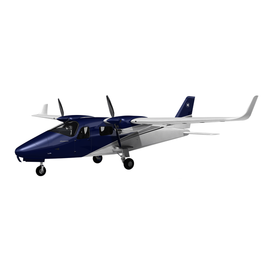
: P2006T
IRCRAFT MODEL
EASA T
C
YPE
ERTIFICATE
S
:...............................................................
ERIAL NUMBER
B
:....................................................................
UILD YEAR
R
EGISTRATION MARKINGS
T
HIS DOCUMENT IS THE
P2006T A
WRITTEN IN
This manual contains information to be furnished to the pilot as required by EASA
in addition to further information supplied by the manufacturer.
This manual must always present on board the aircraft.
The aircraft has to be operated in compliance with procedures and limitations
contained herein.
Costruzioni Aeronautiche TECNAM srl
Via Maiorise
CAPUA (CE) – Italy
Tel. +39 (0) 823.62.01.34
WEB:
www.tecnam.com
Aircraft Flight Manual
Doc. No. 2006/044[EV]
1st Edition – 2009, May 25th
Rev. 0
TECNAM P2006T
N
: A .185 (
O
DATED
:....................................................
F
IRCRAFT
LIGHT
I
TALIAN AND APPROVED BY
TECNAM
S.r.l.
TH
2009, J
5
)
UIN
E
NGLISH TRANSLATION OF
M
–
.
ANUAL
DOC
NO
EASA
ON
st
1
Edition, Rev. 0 – 2009, May 25th
Page 0 - 1
. 2006/044,
25 M
2009
AY
Advertisement
Chapters
Table of Contents

Related Manuals for Tecnam P2006T


Summary of Contents for Tecnam P2006T
- Page 1 This manual must always present on board the aircraft. The aircraft has to be operated in compliance with procedures and limitations contained herein. Costruzioni Aeronautiche TECNAM srl Via Maiorise CAPUA (CE) – Italy Tel. +39 (0) 823.62.01.34 WEB: www.tecnam.com...
- Page 2 Page 0 - 2 INDEX Record of Revisions ..................3 List of Effective Pages .................. 5 Foreword ....................... 7 Sections Index ....................8 Edition, Rev. 0 - 2009, May 25th Aircraft Flight Manual INDEX...
- Page 3 Insert all additional pages in proper numerical order within each section. NOTE: It is the responsibility of the owner to maintain this handbook in a current status when it is being used for operational purposes. Rev. Sec. Page Date Tecnam Approval EASA Approval Or Date Under DOA Privileges D.O. OofA Edition, Rev.
- Page 4 Page 0 - 4 INTENTIONALLY LEFT BLANK Edition, Rev. 0 - 2009, May 25th Aircraft Flight Manual RECORD OF REVISIONS...
- Page 5 Page 0 - 5 IST OF FFECTIVE AGES Pages Rev. Date Section Section 0 Page 1 to 8 Rev 0 May 25 2009 Section 1 Page 1 to 12 Rev 0 May 25 2009 Page 1 to 16 Rev 0 May 25 2009 Section 2 Page 1 to 28...
- Page 6 Page 0 - 6 INTENTIONALLY LEFT BLANK Edition, Rev. 0 - 2009, May 25th Aircraft Flight Manual LIST OF EFFECTIVE PAGES...
- Page 7 Page 0 - 7 OREWORD Tecnam P2006T is a twin-engine four-seat aircraft with high cantilevered wing and tri- cycle retractable landing gear. Section 1 supplies general information and it contains definitions, symbols explanations, acronyms and terminology used. Before using the aircraft, you are recommended to read carefully this manual: a deep knowledge of aircraft features and limitations will allow you for operating the aircraft safely.
- Page 8 Page 0 - 8 ECTIONS NDEX General Section 1 Section 2 Limitations Emergency Procedures Section 3 Normal Procedures Section 4 Section 5 Performances Weight and Balance Section 6 Section 7 Airframe and Systems description Aircraft Care and Maintenance Section 8 Section 9 Supplements Edition, Rev.
- Page 9 Page 1 - 1 SECTION 1 - GENERAL INDEX 01. Introduction ..................... 2 02. Warning – Caution – Note ................2 03. Three-views Drawings ..................3 04. Dimensions ...................... 4 05. Control Surfaces Travel Limits ............... 4 06. Engine ......................5 07.
- Page 10 Page 1 - 2 NTRODUCTION The Aircraft Flight Manual has been implemented to provide the owners with in- formation for a safe and efficient use of the aircraft TECNAM P2006T. – C – N ARNING AUTION Following definitions apply to warnings, cautions and notes used in the Aircraft Flight Manual.
- Page 11 Page 1 - 3 HREE VIEWS RAWINGS Figure 1 – General views Edition – 2009, May 25th Section 1 – General ACRONYMS AND TERMINOLOGY...
- Page 12 Page 1 - 4 IMENSIONS Overall dimensions Wingspan 11,4 m 37,4 ft Length 8,7 m 28,5 ft Overall height 2,85 m 9,35 ft Wing Wing surface 14,76 m 158,9 ft Mean Geometric Chord 1,295 m 4,25 ft Dihedral 1° Aspect ratio 8,80 Main Landing Gear Track...
- Page 13 Page 1 - 5 NGINE Manufacturer Bombardier-Rotax GmbH Model 912 S3 Certification basis FAR 33 - Amendment 15 Type Certificate EASA TCDS no. E.121 dated 1 April 2008 Engine type 4 cylinders horizontally opposed with 1352 c.c. of overall displacement, liquid cooled cylinder heads, ram-air cooled cy- linders, two carburetors, integrated re- duction gear box with shock absorber.
- Page 14 Page 1 - 6 Fuel tanks Two integrated tanks (one in each wing) fitted with drainable sump and drain valve Capacity of each wing tan 100 litres (26,42 US gallons)) Tanks overall capacity 200 litres (52,8 US gallons) Overall usable fuel 194.4 litres (51,35 US gallons) Overall unusable fuel 5.6 litres (1,48 US gallons)
- Page 15 Page 1 - 7 PECIFIC LOADINGS Wing Loading 80 kg/m (16.4 lb/ft Power Loading 6.02 kg/hp CRONYMS AND TERMINOLOGY KCAS Calibrated Airspeed is the indicated airspeed expressed in knots, corrected taking into account the errors related to the instrument itself and its installation. KIAS Indicated Airspeed is the speed shown on the airspeed indicator...
- Page 16 Page 1 - 8 Rotation speed : is the speed at which the aircraft rotates about the pitch axis during takeoff Lift off speed: is the speed at which the aircraft generally lifts off from the ground. Obstacle speed: is the speed at which the aircraft flies over a 15m obstacle during takeoff or landing.
- Page 17 Maximum Landing Weight is the maximum weight approved for the landing touchdown (for P2006T it is equiv- alent to the Maximum Takeoff Weight). Edition – 2009, May 25th Section 1 – General...
- Page 18 Page 1 - 10 NIT CONVERSION CHART MOLTIPLYING YIELDS EMPERATURE Fahrenheit [°F] Celsius [°C] ⋅ − Celsius [°C] Fahrenheit [°F] + ⋅ ORCES Kilograms [kg] 2.205 Pounds [lbs] Pounds [lbs] 0.4536 Kilograms [kg] PEED Meters per second [m/s]...
- Page 19 Page 1 - 11 / US ITRES GALLONS CONVERSION CHART Litres US Gallons US Gallons Litres 11.4 15.1 22.7 30.3 37.9 10.6 45.4 11.9 53.0 13.2 60.6 15.9 68.1 18.5 75.7 21.1 83.3 23.8 90.9 26.4 98.4 29.1 106.0 31.7 113.6 34.3 121.1...
- Page 20 Page 1 - 12 INTENTIONALLY LEFT IN BLANK Edition – 2009, May 25th Section 1 – General...
- Page 21 Page 2 - 1 SECTION 2 – LIMITATIONS INDEX 01. Introduction ....................2 02. Speed limitations ..................2 03. Airspeed indicator markings ................. 3 04. Powerplant limitations .................. 4 05. Lubricant ....................... 5 06. Coolant liquid ....................6 07. Propeller ......................6 08.
- Page 22 Page 2 - 2 NTRODUCTION Section 2 includes operating limitations, instrument markings, and basic placards necessary for safe operation of P2006T aircraft, its engines and standard systems and equipment. PEED LIMITATIONS The following table addresses the airspeed limitations and their operational signifi-...
- Page 23 Page 2 - 3 IRSPEED INDICATOR MARKINGS Airspeed indicator markings and their colour code are explained in the following table. MARKING KIAS SIGNIFICANCE Double white arc Lower limit is V , stall speed at maximum 53-66 weight in landing configuration. Upper limit is the stall speed in “clean”...
- Page 24 Page 2 - 4 OWERPLANT LIMITATIONS Following table reports the operating limitations for both engines installed: : Bombardier Rotax GmbH. NGINE MANUFACTURER : 912 S3 NGINE MODEL AXIMUM POWER Max Power Max rpm. Time max. kW (hp) Prop. rpm (engine) (min.) Max.
- Page 25 Page 2 - 5 Fuel pressure: Minimum 0.15 Bar / 2.2 psi Maximum 0.40 Bar r / 5.8 psi UBRICANT Viscosity Use viscosity grade oil (reference is made to SAE specifications) as specified in the following table: Figure 1 It is not permitted to use oils for aeronautical engines, with or without additives.
- Page 26 Page 2 - 6 OOLANT LIQUID Refer to “Rotax Operator’s Manual” and related documents. ROPELLER MANUFACTURER: MT Propeller MODEL: MTV-21-A-C-F-/CF178-05 TYPE: wood/composite 2-blade, variable pitch hydraulically con- trolled and fully featherable DIAMETER: 1780 mm (no reduction is permitted) OVERNOR MANUFACTURER: MT Propeller MODEL: P-875-12...
- Page 27 Page 2 - 7 OWERPLANT INSTRUMENTS MARKINGS Powerplant instrument markings and their colour code significance are shown be- low: RED LINE GREEN ARC YELLOW ARC RED LINE Minimum Normal Caution Maximum NSTRUMENT limit operating limit Propeller ---- 580 - 2265 2265 - 2388 2388 Oil temp.
- Page 28 Page 2 - 8 ARNING CAUTION AND ADVISORY LIGHTS Following table addresses the warning, caution and advisory lights installed (unless differently specified) on the annunciator panel: Warning (RED) Cause LH OVERVOLT LH electric system overvoltage RH OVERVOLT RH electric system overvoltage MAIN DOOR OPEN ALERT Main door open and/or unlocked REAR DOOR OPEN ALERT...
- Page 29 Page 2 - 9 EIGHTS Condition Weight Maximum takeoff weight 1180 kg 2601 lb Maximum landing weight 1180 kg 2601 lb Maximum baggage weight 80 kg 176 lb Minimum flight weight 856 kg 1887 lb Standard empty weight 760 kg 1675 lb Useful load 420 kg...
- Page 30 Page 2 - 10 PPROVED MANEUVERS The aircraft is certified in normal category in accordance with regulation EASA CS- Non aerobatic operations include: • Any manoeuvre pertaining to “normal” flight • Stalls (except whip stalls) Lazy eights • • Turns in which the angle of bank is not more than 60° Acrobatic manoeuvres, including spins and turns with angle of bank of more than 60°, are not approved for such a category.
- Page 31 Page 2 - 11 LIGHT CONDITIONS The aircraft can be equipped for following flight operations (refer to Section 6 for equipment description): • VFR Day and Night • IFR Day and Night including IMC Flight in expected and/or known icing conditions or in proximity of storms is for- bidden.
- Page 32 Page 2 - 12 IMITATIONS PLACARDS Hereinafter the placards, related to the operating limitations and installed on P2006T, are reported. PEED LIMITATIONS On the left side instrument panel, above on the left, it is placed the following plac- ard reporting the speed limitations:...
- Page 33 Page 2 - 13 NFLIGHT ENGINE RESTART The inflight engine restart procedure is reported on a placard (shown below) in- stalled on the central console. AGGAGE COMPARTMENT CAPACITY The placard shown below and installed on the baggage compartment (vertical panel) deals with the baggage compartment load limitations. Edition –...
- Page 34 Page 2 - 14 NGINE OIL LEVEL On the engine nacelle, in correspondence of the engine oil reservoir access door, it is located the following placard addressing the limitations concerning the oil level, the oil volume and the oil type. UEL TYPE In correspondence of each fuel tank filler cap, it is located the following placard re- porting the approved fuel type and the tank usable fuel.
- Page 35 Page 2 - 15 THER PLACARDS Installed on the left side instrument panel, above on the right, the following placard prescribes the on board smoking ban. INDS OF PERATING QUIPMENT The present paragraph reports the KOEL table, concerning the equipment list re- quired on board to allow flight operations in VFR day, VFR Night and IFR Night conditions.
- Page 36 Page 2 - 16 Equipments Basic Kit Kit A Kit B Kit C Kit D Magnetic compass Airspeed indicator Altimeter Vertical speed indicator Attitude horizon electric Turn Coodinator OAT indicator Pitot system heating Directional (electric) Clock Anti collision lights Breakers panel First aid kit Fire extinguisher Instruments light...
- Page 37 Page 3 - 1 SECTION 3 – EMERGENCY PROCEDURES INDEX 01. Introduction ......................3 02. Failures and warnings list ................... 4 03. Failures indicated on the annunciator panel ............5 3.1 Both generators failure ................5 3.2 Single generator failure ................6 3.3 Both generators overvoltage ...............
- Page 38 Page 3 - 2 7.4 Failed retraction ..................22 7.5 Unintentional landing gear extension ............22 08. Smoke and fire ....................22 8.01 Engine fire on the ground ................22 8.02 Engine fire during takeoff run ..............23 8.03 Engine fire in flight ..................24 8.04 Electrical smoke in cabin with aircraft on the ground ......
- Page 39 Page 3 - 3 NTRODUCTION Section 3 includes checklists and detailed procedures to face the emergency con- ditions that could arise. The emergency conditions caused by a malfunction of the aircraft or its engines are extremely rare if the appropriate maintenance tasks and preflight inspections are carried out.
- Page 40 Page 3 - 4 AILURES AND WARNINGS LIST Hereinafter they are reported likely failures/critical conditions that could arise in flight and that can lead to hazardous situations if not promptly faced in accor- dance with the procedures addressed in this flight manual section. Failures can be identified as: •...
- Page 41 Page 3 - 5 AILURES INDICATED ON THE ANNUNCIATOR PANEL The annunciator panel, located on the left side instrument panel, contains 16 lights for warnings, cautions and advisories. The colours are as follows: GREEN: to indicate the operational status for some systems AMBER: to indicate no-hazard situations which have to be considered and which require a proper crew action...
- Page 42 Page 3 - 6 INGLE GENERATOR FAILURE In event of LH or RH GENERATOR caution light turned ON, apply following procedure: 1. FIELD LH (or RH) If the GENERATOR light stays ON 2. CROSS BUS LH (or RH) The battery and a single generator are able to supply NOTE the electrical power necessary for the entire mission.
- Page 43 Page 3 - 7 if both LH and RH OVERVOLT lights stay ON 3. FIELD LH and RH BOTH OFF 4. CROSS BUS LH and RH BOTH OFF 5. Abort mission and land as soon as possible. The battery can supply electrical power for at least 30 min. NOTE INGLE GENERATOR OVERVOLTAGE In event of LH or RH OVERVOLT warning light turned on, apply the following...
- Page 44 Page 3 - 8 AILED DOOR CLOSURE When a door is open and/or unlocked, related MAIN or REAR DOOR ALERT warning light is turned ON. In this case, apply following procedure: ON THE GROUND Verify door as being correctly closed 2 Try to open the door: if it opens the locking device is damaged 3 Check engine oil pressure 4 Abort mission.
- Page 45 Page 3 - 9 ITOT HEATING SYSTEM FAILURE When the Pitot heating system is activated, the related PITOT HEAT advisory light is turned ON; should the PITOT HEAT FAIL caution light be turned ON, the heating system is electrically supplied but it is damaged. In this case apply following procedure: Pitot heat Pitot heat...
- Page 46 Page 3 - 10 If CHT stabilizes in the green arc, continue the mission If CHT stays high, increase the speed and reduce once more the power If CHT exceeds the limit of 135°C Affected engine : SECURE (see engine securing procedure on PAR. NOTE The shut-down engine restart in flight is permitted, if necessary UMP FAILURE...
- Page 47 Page 3 - 11 NGINE FIRE In event of engine fire, the LH or RH ENGINE FIRE warning light is turned ON. Refer to following procedures: FIRE ON THE GROUND: see PAR. 8.01 FIRE DURING TAKEOFF RUN: see PAR. 8.02 FIRE IN FLIGHT: see PAR.
- Page 48 Page 3 - 12 THER EMERGENCIES 5.1. ROPELLER OVERSPEEDING The aircraft is fitted with propeller/governor set by MT-Propeller such a way that the maximum propeller rpm exceedance is prevented. In case of propeller over- speeding in flight, apply following procedure: Throttle Lever REDUCE power Propeller Lever...
- Page 49 Page 3 - 13 5.3. IL TEMPERATURE LIMIT EXCEEDANCE If oil temperature exceeds maximum limit (130°C), apply following procedure: Maximum oil temperature limit exceedance can be the final ef- fect of different causes: excessive friction between moving en- gine components, thermostatic valve failure, oil leakage from WARNING the circuit (with related pressure reduction) etc.
- Page 50 Page 3 - 14 5.4. IL PRESSURE LIMITS EXCEEDANCE If oil pressure exceeds its limits (0.8 - 7bar), apply following procedure: An excessive oil pressure decreasing leads to a high pitch propeller configuration with consequent propeller feathering WARNING and engine stopping. An excessive oil pressure value can be counteracted by de- NOTE creasing propeller rpm.
- Page 51 Page 3 - 15 If the fuel quantity is not low Electrical fuel pump Fuel press CHECK (verify if come back within the limits) If pressure does not come back within the limits Abort mission and land as soon as possible 5.6.
- Page 52 Page 3 - 16 In this case apply following procedure: Cabin ventilation OFF (hot and cold air) ALTERNATE STATIC PORT VALVE OPEN Continue the mission 5.8. NINTENTIONAL FLIGHT INTO ICING CONDITIONS Carburettor heat BOTH ON Pitot heat Head, if practical, toward a zone with higher temperature, changing alti- tude and/or direction.
- Page 53 Page 3 - 17 During approach/landing In case of unintentional flaps retraction or if the flaps control NOTE fails, consider that the landing distance without flaps increases by about 25%. 1. Airspeed Over 62KIAS 2. Land as soon as possible fully using the runway length and the brakes power NE ENGINE INOPERATIVE PROCEDURES The ineffectiveness of one engine results in an asymmetric traction NOTE...
- Page 54 Page 3 - 18 Stopped engine Propeller Lever FULL FORWARD Start push-button PUSH Propeller Lever SET at desired rpm If the fuel quantity in the tank which feeds the stopped engine is NOTE low, select the opposite side fuel tank by means of the fuel se- lector.
- Page 55 Page 3 - 19 At safe altitude Inoperative engine Propeller Lever FEATHER Inoperative engine SECURE Operating engine monitor engine instruments Operating engine Fuel Selector Check correct feeding/crossfeed if needed Land as soon as possible applying one engine inoperative landing procedure. See PAR. 6.06 6.04 E NGINE FAILURE DURING CLIMB Because the climb is a flight condition associated with high power...
- Page 56 Page 3 - 20 6.06 O NE ENGINE INOPERATIVE LANDING Preparation: Seat belts Tightly fastened Landing lights As required Operating engine Fuel Selector Check correct feeding/crossfeed if needed Inoperative engine Propeller Lever CHECK FEATHER Inoperative engine CHECK SECURED NOTE Perform normal touch down and deceleration on the ground. ANDING GEAR FAILURE 7.1 E MERGENCY LANDING GEAR EXTENSION...
- Page 57 Page 3 - 21 The emergency landing gear extension operation takes about NOTE 20 sec. 7.2 N OSE GEAR UP LANDING The procedure applies in cases where the nose landing gear is not completely extended and locked as a result of applying the emergency extension. In this case: perform landing with nose up attitude and keep nose up as long as pos- sible, then apply aircraft evacuation procedure (see PAR.
- Page 58 Page 3 - 22 7.4 F AILED RETRACTION This procedure applies in case of failed landing gear retraction after takeoff. WARNING Keep the aircraft control Airspeed below 93 KIAS Landing gear control knob DOWN If needed, refer to emergency landing gear extension procedure. See PAR. 7.1 Land as soon as possible NINTENTIONAL LANDING GEAR EXTENSION The unintentional landing gear extension condition is signalled by:...
- Page 59 Page 3 - 23 8.02 NGINE FIRE DURING TAKEOFF RUN Before rotation: abort Throttle Lever BOTH IDLE Rudder Keep heading control Brakes As required With aircraft under control Ignitions ALL OFF Cabin heat and defrost BOTH OFF Fuel Selector BOTH OFF Electrical fuel pump BOTH OFF MASTER SWICTH...
- Page 60 Page 3 - 24 8.03 NGINE FIRE IN FLIGHT Cabin heat and defrost BOTH OFF Fire affected engine Fuel Selector Fire affected engine Throttle Lever FULL FORWARD Fire affected engine Propeller Lever FEATHER Fire affected engine Ignition BOTH OFF Fire affected engine Electrical fuel pump Rudder Keep heading control...
- Page 61 Page 3 - 25 If smoke persists LH and RH Field BOTH OFF In case of fire, direct the fire extinguisher toward the base of flame As fire is extinguished, open cabin ventilation Land as soon as possible and evacuate the aircraft If the MASTER SWITCH is set to OFF, consider that flaps and landing gear (normal mode) extension require battery electri- cal supply.
- Page 62 Page 3 - 26 ANDING EMERGENCIES 10.1. L ANDING WITHOUT ENGINE POWER Both engines failure condition requires both propellers feath- ered and aircraft attitude set to maximum efficiency until the selection of the field, on which to perform an emergency land- CAUTION ing, is made.
- Page 63 Page 3 - 27 10.4. ANDING WITHOUT BRAKES Select an alternate airport (if available) fitted with a run- way longer that the intended destination. Otherwise, as- sess the possibility to perform a gear up landing (refer to CAUTION procedure reported on PAR. 7.3). In order to avoid fire risks for likely collisions, apply fol- NOTE lowing procedures immediately after ground contact...
- Page 64 Page 3 - 28 ITCHING Intentional ditching is forbidden. Following procedure is purely indicative. CAUTION Landing gear Safety belts FASTEN Flaps FULL Before water impact Fuel Selector BOTH OFF Electrical fuel pump BOTH OFF Ignitions ALL OFF MASTER SWITCHES ALL OFF Impact speed 55 KIAS Contact with water must be done with the wave parallel to the direction of flight...
- Page 65 Page 4 - 1 SECTION 4 – NORMAL PROCEDURES INDEX Introduction ...................... 2 Airspeeds for normal operations ..............2 Preflight check ....................2 3.1. Cockpit inspection ........................2 3.2. Aircraft walk-around ........................ 3 Checklists......................7 Before engine starting ..................7 Engine starting ....................
- Page 66 Page 4 - 2 NTRODUCTION Section 4 describes checklists and recommended procedures for the conduct of normal operations for P2006T aircraft. IRSPEEDS FOR NORMAL OPERATIONS The following airspeeds are those which are significant for normal operations. FLAPS 1180kg (2600lb) Rotation Speed (in takeoff, V...
- Page 67 Page 4 - 3 CENTER CONSOLE and CONTROLS 7. Engine controls Check FREE, friction adjustment if needed 8. Flight controls Check FREE 9. Alternate static port Check CLOSED 10. Landing gear emergency controls Remove access door and check OFF 11. Windshield and lateral windows Verify if clean INSTRUMENTS PANEL 12.
- Page 68 Page 4 - 4 for freedom of movement. Always check the ground in the area of the aircraft for evidence of fuel, oil, or operating fluid leakages. FIG. 4-1 Pilot door Check for integrity Left main landing gear Check fuselage skin status, tire status (cuts, bruises, cracks and excessive wear),lubber lines integrity, gear structure and shock ab- sorber, hoses, gear door attachments and...
- Page 69 Page 4 - 5 c) Check radiators. There should be no indication of leakage of fluid and they have to be free of obstructions. ONLY BEFORE FIRST FLIGHT OF A DAY, remove the en- gine cowling and: (1) Check muffle mounting springs for integrity.
- Page 70 Page 4 - 6 Left static port Remove protective cap – Visual inspection Antennas Check for integrity Gear pump and battery compart- Check emergency landing gear extension ment system pressure (operating pressure: 20 ± 4 bar) and battery compartment closure. Horizontal and vertical empennage Check the actuating mechanism of control and tabs...
- Page 71 Page 4 - 7 Radome Check for integrity Radome access door Visual inspection Left Pitot tube Remove protective cap and check for any ob- struction Left cabin ram-air inlet Visual inspection Avoid blowing inside Pitot-tube and inside airspeed indicator system's NOTE static ports as this may damage instruments.
- Page 72 Page 4 - 8 Stabilator trim control Rotate control to full travel checking ex- cursion and instrument indication. Then reset the trim to neutral position. Rudder trim control Operate control to full travel checking excursion and instrument indication. Then reset the trim to neutral position. Flight planning, fuel consumption, fuel Completed refuelling...
- Page 73 Page 4 - 9 LH ignitions switches BOTH ON LH start pushbutton PUSH LH engine oil gauge CHECK if increasing within 10 sec. (max 7 bar in cold operation) LH engine instruments CHECK if within green arc LH propeller rpm 1100-1200 rpm LH Choke LH Field...
- Page 74 Page 4 - 10 AXIING NOTE Ensure that the main and passengers doors warning lights are turned off. Brakes TEST Flight instruments TEST RIOR TO TAKEOFF Brakes ENGAGED RH Fuel Selector RIGHT LH Fuel Selector LEFT LH and RH Engine parameters checks: •...
- Page 75 Page 4 - 11 AKEOFF AND CLIMB Call TWR for takeoff Check for clear final and wind on run- Direction and intensity LH and RH Electrical Fuel pump BOTH ON Parking Brakes RELEASE Carburettors heat Taxi to line-up Magnetic compass and heading indica- CHECK LH and RH Propeller Lever FULL FORWARD...
- Page 76 Page 4 - 12 EFORE LANDING LH and RH Electrical Fuel pump BOTH ON On downwind leg Speed 75 KIAS; Flaps: T/O Landing gear DOWN – Check green lights turning LH and RH Throttle Lever As required LH and RH Propeller Lever FULL FORWARD On final leg Speed: 65KIAS;...
- Page 77 Page 4 - 13 Parking Brakes CHECK ENGAGED Passengers Open passengers door and allow them for leaving the aircraft paying attention to the propeller disc. 4.12 OSTFLIGHT CHECKS Employ protective caps for Pitot tubes and static ports. Lock the control wheel with safety belt. Place wheel chocks for the main landing gear and the lock for aileron control.
- Page 78 Page 4 - 14 INTENTIONALLY LEFT BLANK Edition, Rev. 0 – 2009, May 25th Section 4 – Normal procedures...
- Page 79 Page 5 - 1 SECTION 5 - PERFORMANCES INDEX Introduction ....................2 Use of performances charts ..............2 Airspeed indicator system calibration ............3 ICAO Standard Atmosphere ............... 4 Stall speed ....................5 Crosswind ....................6 Cruise ......................7 Takeoff performances ................9 Landing performances ................
- Page 80 Page 5 - 2 01. I NTRODUCTION This section provides all necessary data for an accurate and comprehensive plan- ning of flight activity from takeoff to landing. Data reported in graphs and/or in tables were determined using: • “Flight Test Data” under conditions prescribed by EASA CS-23 regulation •...
- Page 81 Page 5 - 3 IRSPEED INDICATOR SYSTEM CALIBRATION Graph shows calibrated airspeed V as a function of indicated airspeed V Figure 1 - IAS/CAS chart Example: Given Find KIAS 75 KCAS 74 Edition, Rev. 0 – 2009, May 25th Section 5 - Performances AIRSPEED INDICATOR SYSTEM CALIBRATION...
- Page 82 Page 5 - 4 ICAO S TANDARD TMOSPHERE Figure 2 – ICAO chart Example: Given Find Temperature = 20°C Ts = 12° Pressure altitude = 1600 ft Edition, Rev. 0 – 2009, May 25th Section 5 - Performances ICAO STANDARD ATMOSPHERE...
- Page 83 Page 5 - 5 05. S TALL SPEED ONDITIONS - Weight 1180 kg - Throttle levers: IDLE - Landing gear: DOWN - No ground effect - CG in middle position (22% C.G.) NOTE Altitude loss during conventional stall recovery, as demonstrated during flight tests is approximately 180 ft with banking below 30°.
- Page 84 Page 5 - 6 06. C ROSSWIND Maximum demonstrated crosswind is 17 Kts ⇒ Example: Given Find Wind direction ( Headwind = 17.5 Kts with respect to air- ) = 30° craft longitudinal axis Wind speed = 20 Kts Crosswind = 10 Kts Figure 3 –...
- Page 85 Page 5 - 7 07. C RUISE P2006 T-Level speed ( kts ) - Maximum Takeoff Weight - ISA Conditions Pressure altitude = S.L. 1895 1975 2060 2265 F.T. 29,5 Pressure altitude = 3000 FT 1895 1975 2060 2265 F.T. 26,8 Pressure altitude = 6000 FT 1895 1975...
- Page 86 Page 5 - 8 Pressure altitude = 9000 FT 1895 1975 2060 2265 F.T. 21,4 Pressure altitude = 12000 FT 1895 1975 2060 2265 F.T. 19,02 Dark highlighted the set points to be avoided (higher consumption) Edition, Rev. 0 – 2009, May 25th Section 5 - Performances CRUISE...
- Page 87 Page 5 - 9 08. T AKEOFF PERFORMANCES Takeoff ground roll CONDITIONS: • Flaps: T/O • Throttle levers: FULL FORWARD • Lift-Off speed: 66,5 KIAS • Runway: grass Figure 4 - Takeoff ground roll In case of headwind, the takeoff run decreases by 2.5m for each NOTE knot of wind (8 ft/kt).
- Page 88 Page 5 - 10 Takeoff distance CONDITIONS: • Flaps: T/O • Throttle levers: FULL FORWARD • Lift-Off speed: 66.5 KIAS • Runway: grass Figure 5 - Takeoff distance (50 ft. Obs) In case of headwind, the takeoff run decreases by 4m for each NOTE knot of wind (13 ft/kt).
- Page 89 Page 5 - 11 09. L ANDING PERFORMANCES Landing ground roll CONDITIONS : • Flaps: FULL • Throttle levers: IDLE • Runway: grass • Short Final Approach Speed 67 KIAS Figure 6 - Landing ground roll In case of headwind, the landing run decreases by 3.5m for each NOTE knot of wind (11.5 ft/kt).
- Page 90 Page 5 - 12 Landing distance over 15m (50ft) CONDITIONS: • Flaps: FULL • Throttle levers: IDLE • Runway: grass • Short Final Approach Speed 67 KIAS Figure 7 - Landing distance over 15 m obstacle In case of headwind, the landing run decreases by 5m for each knot of wind (16 ft/kt).
- Page 91 Page 5 - 13 10. C LIMB PERFORMANCE BOTH ENGINES OPERATIVE CONDITIONS: • A/C Clean configuration • Both engines operative • Max Cont. Power - Airspeed 80 kias Figure 8 – Rate of Climb (both engines operative) Edition, Rev. 0 – 2009, May 25th Section 5 - Performances CLIMB PERFORMANCE (BOTH ENGINES OPERATIVE)
- Page 92 Page 5 - 14 CLIMB PERFORMANCE ONE ENGINE INOPERATIVE CONDITIONS: • AC Clean configuration • One engine inoperative • Max Cont. Power - Airspeed 80 kias Figure 9 – Rate of Climb (one engine inoperative) Edition, Rev. 0 – 2009, May 25th Section 5 - Performances CLIMB PERFORMANCE (ONE ENGINE INOPERATIVE)
- Page 93 Page 5 - 15 12. R ATE OF CLIMB Flight conditions (ISA and SL): Throttle levers Both FULL FORWARD Flaps Landing gear DOWN Peso MTOW Speed 66 KIAS Constant Rate of Climb 3.5° 13. N OISE DATA Noise level, determined in accordance with ICAO/Annex 16 4th Ed., July 2005, Vol.
- Page 94 Page 5 - 16 INTENTIONALLY LEFT IN BLANK Edition, Rev. 0 – 2009, May 25th Section 5 - Performances NOISE DATA...
- Page 95 Page 6 - 1 SECTION 6 – WEIGHT and BALANCE INDEX 01. Introduction ..................... 2 02. Weighing procedures ..................2 Preparation ....................2 Levelling ...................... 2 Weighing ...................... 3 Determination of C.G. location ..............3 Weighing record ................... 4 Weighing record (II) ..................5 03.
- Page 96 Page 6 - 2 NTRODUCTION This section describes the procedure for establishing the basic empty weight and the moment of the aircraft. Loading procedure information is also provided. Aircraft must be operated in accordance with the limits con- NOTE cerning the maximum takeoff weight and CG excursion as re- ported in Flight Manual Section 2.
- Page 97 Page 6 - 3 EIGHING Record weight shown on each scale Repeat weighing procedure three times Calculate empty weight C.G. ETERMINATION OF LOCATION Drop a plumb bob tangent to the wing leading edge and trace a reference mark on the floor (see figure on PAR. 05) Repeat the operation for other wing Stretch a taught line between the two marks Measure the distance between the reference line and both main and nose wheel...
- Page 98 Page 6 - 4 EIGHING RECORD Model P2006T S/N:________ Weighing no. ____ Date:_________ Datum: leading edge vertical meters Nose wheel weight W Plumb bob distance LH wheel LH wheel weight Plumb bob distance RH wheel RH wheel weight Average distance (A...
- Page 99 Page 6 - 5 (II) EIGHING RECORD Model P2006T S/N:________ Weighing no. ____ Date:_________ Datum: leading edge vertical meters Nose wheel weight W Plumb bob distance LH wheel LH wheel weight Plumb bob distance RH wheel RH wheel weight Average distance (A...
- Page 100 Page 6 - 6 C.G. EIGHTS AND C.G. position can be defined by means of the chart below. The pilot is responsible for ensuring the correct useful load loading. Figure 1 Example A/C empty mass moment 378 kgm A/C empty mass 790 kg Occ.
- Page 101 Page 6 - 7 OADING The baggage loading in the dedicated compartment must be carried out in accor- dance with diagram addressed on PAR. 03 and with C.G. excursion and weight limitations reported in Section 2. Pilot is provided with a red tie-down net and snap fasteners allowing for securing the loads on the compartment floor.
- Page 102 Page 6 - 8 QUIPMENT LIST The following is a comprehensive list of all TECNAM supplied equipment for the P2006T. The list consists of the following groups: A - Engine and accessories B - Landing gear C - Electrical system...
- Page 103 Page 6 - 9 _____ QUIPMENT LIST IRCRAFT S EIGHT ESCRIPTION AND P LANDING GEAR & ACCESSORIES Main landing gear rim and brake disc - Cleveland 40-59 0.78 Main landing gear tire - Tube 6.00-6 Air Trac 06-08700 0.78 Brakes - Cleveland Kit 199-102 0.78 Nose landing gear rim.
- Page 104 Page 6 - 10 _____ QUIPMENT LIST IRCRAFT S EIGHT ESCRIPTION AND P ELECTRICAL SYSTEM 12.2 Battery GILL G 35 12V 23Ah Landing light General Electric GE4509 Battery relay White Rogers 70-111226-5 Flaps actuator – AMER/SIR 1.05 DC “baby” ACTUATOR AO-01/M 0.15 Rudder Trim actuator Bristol S.G.
- Page 105 Page 6 - 11 _____ QUIPMENT LIST IRCRAFT S EIGHT ESCRIPTION AND P INSTRUMENTATION Altimeter - United Instruments 5934PM-3A84 -1.4 01770028-05 Airspeed indicator – UMA T16-311-200 0.37 -1.4 0.15 Magnetic Compass – Airpath 2400-L4VT -1.4 Chronometer Aviatec M800-14VB -1.4 Vertical speed indicator – 7000- United Instruments -1.4 Turn and bank indicator –...
- Page 106 Page 6 - 12 _____ QUIPMENT LIST IRCRAFT S EIGHT ESCRIPTION AND P AVIONICS & MISCELLANEOUS GPS/NAV Receiver and R/T COM Garmin GNS 430W 010- -1.4 00139-11 ELT Adams Aviation Artex ME406 -1.4 Transponder-Garmin GTX328 -1.4 Audio panel –Garmin GMA 340 010-00152-11 Vor/Loc/GS Indicator–Garmin GI106A -1.4 -0.55...
- Page 107 Page 6 - 13 _____ QUIPMENT LIST IRCRAFT S EIGHT ESCRIPTION AND P AVIONICS & MISCELLANEOUS Antenna DME KA 60 -1.1 Electric longitudinal trim Stabilator trim S-Tec 0105-T11 HONEYWELL Bendix/King KCS 55A Compass System KI 525A Pictorial Navigation Indicator 1.53 -1.4 KA 51B Slaving Control and Compensator Unit -1.4...
- Page 108 Page 6 - 14 INTENTIONALLY LEFT BLANK Edition, Rev. 0 – 2009, May 25th Section 6 – Weight and balance EQUIPMENT LIST...
-
Page 109: Table Of Contents
Page 7 - 1 SEZIONE 7 – AIRFRAME and SYSTEMS DESCRIPTION INDICE 01. Introduction ..................... 2 02. Airframe ......................2 2.1. Wing ......................2 2.2. Fuselage....................... 3 2.3. Empennages ....................4 2.4. Flight controls ....................5 03. Instruments panel ................... 6 Carburettor heat .................. -
Page 110: Introduction
Page 7 - 2 NTRODUCTION This section provides aircraft and its systems description and operation. IRFRAME 2.1. W The wing consists of a central light alloy torque box; an aluminium leading edge is attached to the front spar while flap and aileron are hinged to rear spar. Flaps and ailerons, light alloy made, are constructed with a central spar to which front and rear ribs are jointed;... -
Page 111: Fuselage
Page 7 - 3 2.2. F USELAGE The fuselage is constituted by a light-alloy semi-monocoque structure wrapped- around by stressed skin panels. Radome and stern fairing are of composite mate- rial. Cabin and baggage compartment floor is a warping of beams and keelsons supporting the seats guides and other components. -
Page 112: Empennages
Page 7 - 4 2.3. E MPENNAGES The vertical tail is entirely metallic: vertical fin is made up of a twin spar with aluminium alloy stressed skin. Rudder also is made up of aluminium alloy. The horizontal empennage is an all-moving type (stabilator); its structure consists of a twin spar to which front and rear ribs are jointed and it is covered by stressed alu- minium alloy skin. -
Page 113: Flight Controls
Page 7 - 5 Figure 4 – Stabilator structure 2.4. F LIGHT CONTROLS Aircraft flight controls are operated through stick and rudder pedals. Longitudinal control acts through a system of push-rods moving the stabilator whose antitab winglet works also as trim tab. Aileron control is of mixed type with push-rods and cables;... -
Page 114: Instruments Panel
Page 7 - 6 NSTRUMENTS PANEL Figure 5 – Instruments panel Edition, Rev. 0 – 2009, May 25th Section 7 – Airframe and Systems description INSTRUMENTS PANEL... -
Page 115: Carburettor Heat
Page 7 - 7 ARBURETTOR HEAT Carburettor heat control knob is located on the central console; when the knob is fully pulled backwards, carburettor receive maximum hot air. During normal op- erations, the knob is set OFF. ENTILATION If required, pilot allows for ram-air entering the cabin via the two outlet ports re- spectively located on the left and right side of the instruments panel. - Page 116 Page 7 - 8 Figure 6 – Central console Number Description Choke Choke Friction Knob Throttle Friction Knob LH and RH Throttle LH and RH Carburetor Heating 9-10 LH and RH Propeller Pitch Control Parking brake Edition, Rev. 0 – 2009, May 25th Section 7 –...
-
Page 117: Landing Gear Control Knob
Page 7 - 9 ANDING GEAR CONTROL KNOB The landing gear control knob is centrally located under the instruments panel. To extend the landing gear, the knob is put in DOWN position. ABIN HEAD PANEL Figure 7 – Cabin head panel controls Number Description Cabin Light... -
Page 118: Seats And Safety Belts
Page 7 - 10 EATS AND SAFETY BELTS In correspondence of the seats, three fitting points safety belts are provided; belt adjustment is via the sliding buckle located on the belt metal hook. Seats are built with light alloy tube structure and synthetic material cushioning. It is possible to perform following seat adjustments: Horizontal –... -
Page 119: Powerplant
Page 7 - 11 OWERPLANT 4.1. E NGINES Manufacturer Bombardier-Rotax GmbH Model 912 S3 Certification basis FAR 33, Amendment 15 Type Certificate EASA TCDS no. E.121 dated 1st April 2008 Engine type 4 cylinders horizontally opposed with 1352 c.c. of overall displacement, liquid cooled cylinder heads, ram-air cooled cylinders, two carburetors, integrated reduction gear box with shock absorber. -
Page 120: Fuel System
Page 7 - 12 UEL SYSTEM Fuel system consists of two integrated tanks inside the wing torque boxes (as shown in Figure 8) fitted with inspection doors. Each one has a capacity of 100 li- tres. The three-position fuel selectors are located in the cabin. Left fuel selector allows for managing left engine feeding. - Page 121 Page 7 - 13 Figure 8 – Fuel system schematic Edition, Rev. 0 – 2009, May 25th Section 7 – Airframe and Systems description FUEL SYSTEM...
-
Page 122: Electric System
Page 7 - 14 LECTRIC SYSTEM The electric system has a nominal direct current of 14Vdc which can be shared between following distribution bus bars: • Battery bus bar • Left generator bus bar • Right generator bus bar • Left avionics bus bar •... - Page 123 Page 7 - 15 Figure 9 – Electric system schematic Edition, Rev. 0 – 2009, May 25th Section 7 – Airframe and Systems description ELECTRIC SYSTEM...
- Page 124 Page 7 - 16 To the battery bus bar it is connected the equipment essential for the flight, that • Landing gear system • Electric fuel pumps • Engine instruments • Fuel quantity indicators • Strobe lights • Flaps • Instruments lights •...
-
Page 125: Brakes
Page 7 - 17 RAKES Figure 10 shows the brakes system schematic. Main landing gear wheels have an independent braking system. The oil reservoir (4) is directly connected to the brake cylinders (3) of the co-pilot pedals (1). Flexible hoses connect the co-pilot brake cylinders whit those belonging to the pilot pedals. -
Page 126: Landing Gear
Page 7 - 18 ANDING GEAR The landing gear system is tricycle retractable type and hydraulically operated for extension and retraction operation. An electric gear pump, activated via the control knob placed under the instruments panel, pressurizes oil sent toward the hydraulic actuators (one for each wheel) which ensure legs movement. - Page 127 Page 8 - 1 SEZIONE 8 – AIRCRAFT CARE and MAINTENANCE 01. Introduction ....................2 02. Inspection intervals ..................2 03. Aircraft changes or repairs ................2 04. Maintenance ....................3 4.01. Refuelling ........................3 4.02. Oil level control ......................3 4.03.
-
Page 128: Introduction
Page 8 - 2 NTRODUCTION This Section deals with main care and maintenance operations for P2006T. Refer to Aircraft Maintenance Manual to establish the controls / inspections / maintenance tasks (scheduled and unscheduled) to be performed. NSPECTION INTERVALS Scheduled inspections must be performed every 100/600/1200 hours. Independ- ently from the aircraft flight hours, an annual inspection has to be performed. -
Page 129: Maintenance
Page 8 - 3 AINTENANCE 4.01. EFUELLING - Do not perform aircraft refuelling near flames, sparks or similar. - Avoid fuel contact with the skin: a skin corrosion could occur. - Make sure that a fire extinguisher is available nearby during re- fuelling operations. -
Page 130: Ground Towing And Parking
Page 8 - 4 5. If required, rectify the pressure (nose tire 1.7 Bar / 24 Psi, main landing gear tires 2,3 Bar / 33 Psi) 6. Install the inflation opening protective cap 7. Install wheel rim fairing (on main LG wheels) ROUND TOWING AND PARKING 5.01 OWING... -
Page 131: Propeller
Page 8 - 5 Died insects must be removed using hot water. It is advisable to avoid outside aircraft parking for long periods; it is always con- venient to keep the aircraft in the hangar. ROPELLER To preserve its functionality avoiding wear and corrosion, the propeller manufac- turer uses, for external surface painting, an acrylic paint which is resistant to all solvents. - Page 132 Page 8 - 6 INTENTIONALLY LEFT BLANK Edition, Rev. 0 – 2009, May 25th Section 8 – Aircraft Care and Maintenance...
- Page 133 Page 9 - 1 SECTION 9 – SUPPLEMENTS INDEX 01. Introduction ..................... 3 02. Supplements list ..................... 3 Supplement no. 1 - Garmin GNS-430W GPS/WAAS COMM/NAV ......4 INTRODUCTION ...................... 4 GENERAL ........................ 4 LIMITATIONS ......................5 EMERGENCY PROCEDURES ................... 5 NORMAL OPERATIONS ...................
- Page 134 Page 9 - 2 EMERGENCY PROCEDURES ..................11 NORMAL OPERATIONS ..................12 PERFORMANCES ....................12 WEIGHT AND BALANCE ..................12 SYSTEMS .......................12 Supplement no. 5 – KR 87 ADF System ..............13 INTRODUCTION .....................13 GENERAL .......................13 LIMITATIONS ......................13 EMERGENCY PROCEDURES ..................13 NORMAL OPERATIONS ..................14 PERFORMANCES ....................14 WEIGHT AND BALANCE ..................14 SYSTEMS .......................14...
- Page 135 Page 9 - 3 NTRODUCTION This Section concerns the supplemental manuals of additional (or optional) instrumenta- tion equipping the P2006T. UPPLEMENTS LIST Aircraft S/N: Registration marks: Date: APPLICABLE: Sup. No. Title Rev. no. Date Garmin GNS-430W Gps/VHF Comm/Nav Garmin SL30...
- Page 136 Page 9 - 4 . 1 - G GNS-430W GPS/WAAS UPPLEMENT NO ARMIN COMM/NAV INTRODUCTION This section contains supplemental information to operate, in a safe and efficient manner, the aircraft when equipped with Garmin GNS-430W device. GENERAL 1. GPS GNS-430W is an integrated system which contains, in addition to the GPS navigation system, a VHF COMM transceiver and a VOR/ILS receiver.
- Page 137 Page 9 - 5 LIMITATIONS 1. The “Pilot’s guide and Reference” p/n 190-00356-000 rev. D, or a more updated version, must be available for the correct device use. 2. The system employment is allowed only in VFR flight conditions. 3. GPS system must employ the following, or more updated, approved software versions: Software Item Approved software version...
- Page 138 Page 9 - 6 to integrate them with data drawn from other approved navigation instruments: should the advice appear during a GPS approach, this one cannot be performed. It shall be necessary to perform the manoeuvre with other approved navigation instruments. 4.
- Page 139 SL30 transmits with a power of 8watt. LIMITATIONS Garmin SL30 manuals do not address operating limitations more severe than those usually applicable to the P2006T. EMERGENCY PROCEDURES 1. Should Garmin SL30 information be unavailable or manifestly wrong, it is necessary to use other communication devices.
- Page 140 Page 9 - 8 2. INFO SL30 ABOUT ARMIN SOFTWARE SL30 data can be recalled on the screen holding pushed the SYS button and rotat- ing the bigger knob until the “system info page” visual display appears, then push- ing ENT. PERFORMANCES Garmin GNS SL30 employment does not affect the aircraft performances.
- Page 141 Garmin GMA340 device. GENERAL Garmin GMA340 is the audio management device used on P2006T. The audio panel handles internal audio communications (INTERCOM), external audio communications (allowing COM1 to COM2 switching), those related to the markers during ILS approaches and, eventually, those related to the on board mu- sical entertainment (compact disc devices etc).
- Page 142 Page 9 - 10 PERFORMANCES Garmin GMA340 audio panel employment does not affect the aircraft performances. WEIGHT AND BALANCE See Section 6 of this Manual. SYSTEMS Refer to the guide “GMA340” p/n 190-00149-10 rev. C dated 2001 or later versions for a complete system description.
- Page 143 Garmin GTX 328 is a transponder operating with A,C and S mode. LIMITATIONS Garmin GTX 328 manuals do not address operating limitations more severe than those usually applicable to the P2006T. EMERGENCY PROCEDURES In case of emergency conditions, transponder is able to sent codified messages to the Air Traffic Control;...
- Page 144 Page 9 - 12 NORMAL OPERATIONS ETAILED OPERATING PROCEDURES Normal operating procedures are described on “Pilot’s guide and Reference” P/N 190- 00420-03 rev. A dated January 2007 or later versions. PERFORMANCES Garmin GTX328 employment does not affect the aircraft performances WEIGHT AND BALANCE See Section 6 of this Manual.
- Page 145 LIMITATIONS ADF KR 87 manuals do not address operating limitations more severe than those usually applicable to the P2006T. EMERGENCY PROCEDURES Particular meteorological conditions can distort the equipment indications. There- fore, to avoid false indications about NDB direction, it is necessary to select ANT function in order to query the selected station and to listen to its identification code.
- Page 146 Page 9 - 14 Near electrical interferences (electrical storms), ADF indicator tends to head to- ward the interferences themselves. Take into account this likelihood when the in- dicator heads, for example, toward highly cloudy or stormy zones. Wrong indications could arise also during night flights, near mountainous reliefs and as effect of the coastal refraction.
- Page 147 NAV1. LIMITATIONS DME KN 63 manuals do not address operating limitations more severe than those usually applicable to the P2006T. EMERGENCY PROCEDURES In determined conditions, near the beacon, DME signal can be lost or distorted.
- Page 148 Page 9 - 16 SYSTEMS Refer to the guide “KN 63 Installation Manual ”, P/N 006-00176 Rev. 4 dated October 2004 for a complete system description. Edition, Rev. 0 - 2009, May 25th Section 9 - Supplements Supplement no. 6 – KN 63 DME System...
- Page 149 LIMITATIONS KCS 55A manuals do not address operating limitations more severe than those usually applicable to the P2006T. EMERGENCY PROCEDURES If the power warning flag appears on the indicator, the system has experienced a power failure and the card indications are in error.
- Page 150 Page 9 - 18 WEIGHT AND BALANCE See Section 6 of this Manual. SYSTEMS Refer to the guide “KCS Installation Manual ”, P/N 006-00111-0011 Rev. 11 dated April 2007 for a complete system description. Edition, Rev. 0 - 2009, May 25th Section 9 - Supplements Supplement no.
Need help?
Do you have a question about the P2006T and is the answer not in the manual?
Questions and answers