Advertisement
Quick Links
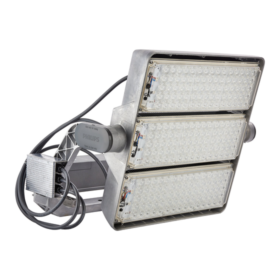
OptiVision LED gen2
Floodlight
BVP525/BVP515
BVP525
100000h
BVP525
100000h
BVP525
100000h
BVP525
100000h
BVP525
100000h
BVP525
100000h
BVP525
100000h
BVP525
100000h
BVP525
100000h
BVP525
100000h
BVP525
100000h
BVP525
100000h
BVP525
100000h
BVP525
100000h
BVP525
100000h
BVP525
100000h
BVP525
100000h
BVP525
100000h
BVP525
50000h
BVP525
50000h
BVP525
50000h
BVP525
50000h
BVP525
50000h
BVP525
50000h
BVP525
50000h
BVP525
50000h
BVP525
50000h
443000017273_B
© 2 / 2016, Philips Lighting Holding B.V. All rights reserved
757
194000
1471
757
186000
1392
757
179000
1314
757
171000
1236
757
163000
1160
757
155000
1082
757
142000
964
757
142000
964
757
129000
845
740
185000
1471
178000
1392
740
740
171000
1314
740
164000
1236
740
156000
1160
740
148000
1082
740
136000
964
740
136000
964
740
124000
845
194000
1471
757
757
194000
1471
757
194000
1471
757
186000
1392
757
179000
1314
757
171000
1236
757
163000
1160
757
163000
1160
142000
964
757
BVP525 HGB
BVP525 BV
HGB
15° C
-
-40° C
31,5
20° C
-
-40° C
31,5
25° C
-
-40° C
31,5
30° C
-
-40° C
31,5
35° C
-
-40° C
31,5
40° C
-40° C
31,5
45° C
-40° C
31,5
-
35° C
-40° C
31,5
-
45° C
-40° C
31,5
15° C
-
-40° C
31,5
20° C
-
-40° C
31,5
25° C
-
-40° C
31,5
30° C
-
-40° C
31,5
35° C
-
-40° C
31,5
40° C
-40° C
31,5
45° C
-40° C
31,5
-
35° C
-40° C
31,5
-
45° C
-40° C
31,5
15° C
-
-40° C
31,5
20° C
-
-40° C
31,5
25° C
-
-40° C
31,5
30° C
-
-40° C
31,5
35° C
-
-40° C
31,5
40° C
-40° C
31,5
45° C
-40° C
31,5
-
35° C
-40° C
31,5
-
45° C
-40° C
31,5
1/16
BVP515 HGB
1,25
RG2
15º
40º
BV
0,39
0,48
25
0,39
0,48
25
0,39
0,48
25
0,39
0,48
25
0,39
0,48
25
0,39
0,48
25
0,39
0,48
25
0,39
0,48
25
0,39
0,48
25
0,39
0,48
25
0,39
0,48
25
0,39
0,48
25
0,39
0,48
25
0,39
0,48
25
0,39
0,48
25
0,39
0,48
25
0,39
0,48
25
0,39
0,48
25
0,39
0,48
25
0,39
0,48
25
0,39
0,48
25
0,39
0,48
25
0,39
0,48
25
0,39
0,48
25
0,39
0,48
25
0,39
0,48
25
0,39
0,48
25
Printed in Spain
Data subject to change without notice
Keep for future reference: www.philips.com/lighting
BVP515 BV
15º
40º
0,23
0,32
0,23
0,32
0,23
0,32
0,23
0,32
0,23
0,32
0,23
0,32
0,23
0,32
0,23
0,32
0,23
0,32
0,23
0,32
0,23
0,32
0,23
0,32
0,23
0,32
0,23
0,32
0,23
0,32
0,23
0,32
0,23
0,32
0,23
0,32
0,23
0,32
0,23
0,32
0,23
0,32
0,23
0,32
0,23
0,32
0,23
0,32
0,23
0,32
0,23
0,32
0,23
0,32
Advertisement

Related Manuals for Philips BVP525 HGB


Summary of Contents for Philips BVP525 HGB
- Page 1 0,32 BVP525 50000h 142000 45° C -40° C 31,5 0,39 0,48 0,23 0,32 Printed in Spain 443000017273_B Data subject to change without notice 1/16 © 2 / 2016, Philips Lighting Holding B.V. All rights reserved Keep for future reference: www.philips.com/lighting...
- Page 2 15º 40º 15º 40º BVP525 50000h 185000 1471 15° C -40° C 0,39 0,48 0,23 0,32 BVP525 50000h 185000 1471 20° C -40° C 0,39 0,48 0,23 0,32 BVP525 50000h 185000 1471 25° C -40° C 0,39 0,48 0,23 0,32 BVP525 50000h 178000...
- Page 3 BVP525 HGB BVP525 BV BVP515 HGB BVP515 BV HGB VERSION BV VERSION BRACKET FIXATION DETAIL 3/16...
- Page 4 In case of using only one fixation point and if the luminaire is higher >3m, the use of a 2nd fixing security system is needed RECOMMENDED WASHER The fasteners have to resist environment corrosion. ACCORDING TO DIN9021 Stainless steel screws not recommended and protective coating might be applied.
-
Page 5: Maintenance
MAINTENANCE Mark the position with a pen (to remember the posi- tion) before untighting the grub screw and rotate the luminaire. Disconnect from connection Connect the cable of the module to the connection Rotate back to the marked position before tightening 5/16... -
Page 6: Cleaning Techniques
LIGHT MODULE LABEL OPTIC TYPE 12 NC: 9123XXXXXXXX S2 TO S8 I : 0,8-2,0 A Tc: 90ºC OPTIC TYPE NB/MB/WB/VBW CLEANING 1. Remove physical elements that can block and modify the aircooling (heatsink fins) 2. Cleaning Frequency (depending on installa- tion place and environment) Pollution Category Cleaning Interval... - Page 7 ACCESORIES LOUVRE (8x) 4x10mm screws 12NC: 912300022867 (ZVP520 L-A90): External zero candela louvre (8x) 4x10mm screws 12NC: 912300022990 (ZVP520 L-A90): External zero candela louvre PRECISION AIMING DEVICE ZVP520 PAD A30 (for A-Optics) 12NC: 910503910040 ZVP420 PAD A0 (for S-Optics) 12NC: 910503910039 BOTTOM ZVP520 PAD A30 (for A-Optics) ZVP420 PAD A0 (for S-Optics)
- Page 8 EVP500 OptiVision LED gen2 Driver box EVP500 Driver box Features Iin (Mains 230V) 2.5A-6.4A Iin (Mains 400V) 1.6A-3.7A Inrush (230V) 18 A during 160 µs Inrush (400V) 30 A during 160 µs Power Factor > 0.95 at full power Surge Protection 10kV Standard Maximum Heat Disipation* * According to the maximum heat disipation, a thermal study should be done for a cabinet installation...
- Page 9 ELECTRICAL CONNECTION (HGB AND BV VERSION) DALI MAINS Cable from Driver box to Connection Box CONNECTION CONNECTION MAINS MAINS DALI Dmin Dmax TORQUE (Nm) M20 (DALI Cable) M25 (MAINS Cable) Recommended cable diameter DALI: Ø10mm-Ø14mm Recommended cable diameter MAINS: Ø13mm-Ø18mm 9/16...
- Page 10 WIRING CONNECTION BOX BOTTOM MIDDLE BOTTOM Module Module Module Module Module BVP515 BVP525 Maximum distance from driver box to luminaire 200m The cross section rules with regard to voltage drops over long distances applies and the choice of cable cross-sec- tion and also cabling way remains under responsibility of the installer.
- Page 11 How to connect a cable with length between 50m and 200m 50m<L<200m 3 pole connector (1 pole in 2 pole out, not supplied by Philips ), to be installed inside the driver box 11/16...
- Page 12 Installation of drivers boxes on cabinet ORIENTATION DISTANCES Each driver box in the cabinet has to be in vertical position The distances between driver box- es or wall have to be higher than: Item Distance 1, 3 Min 50mm Min 80mm Min 150mm Min 200mm Cables...
- Page 13 Installation of driver boxes in the mast minimum width of the door: 125mm minimum height of the door: 600mm Depending of the driver fixation in the mast, please select the most suitable hook. 13/16...
- Page 14 Installation of driver boxes on the bracket or in horizontal position BOTTOM Breathers cannot be exposed directly to water 14/16...
- Page 15 Maximum number of luminaires to be connected to standard circuit breakers (fuse) BVP515 Mains voltage Max Nr luminaires connected MCB 16A A type 230V MCB 16A B type 230V MCB 32A A type 230V MCB 32A B type 230V MCB 16A A type 400V MCB 16A B type 400V...
- Page 16 © 2016 Philips Lighting Holding B.V. All rights reserved Reproduction in whole or in part is prohibited without consent of the copyright owner The information presented in ths document does not form part of any quotation or contract is believed to be accurate and reliable and may be changed without notice.
Need help?
Do you have a question about the BVP525 HGB and is the answer not in the manual?
Questions and answers