Table of Contents
Advertisement
Quick Links
Advertisement
Table of Contents

Related Manuals for TECH ST-402N PWM


Summary of Contents for TECH ST-402N PWM
- Page 1 Tech User’s manual ST-402N PWM - 1 -...
-
Page 2: Safety
ST-402N User's Manual v 1.0.3 I. Safety Before using the device for the first time the user should read the following regulations carefully. Not obeying the rules included in this manual may lead to personal injuries and device damage. The user's manual should be stored in a safe place for further reference. -
Page 3: Application
Tech Application The ST-402N type temperature regulator is intended for the operation of solar collectors for various system configurations. This device controls the operation of collector pumps (or a pump and a valve) on the basis of the measurement of the solar panel temperatures and the accumulation tank (two tanks) temperature. -
Page 4: Iv. User Menu
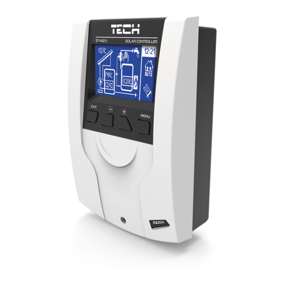
ST-402N User's Manual v 1.0.3 IV. User Menu IV.a) Home Page During the regulator's standard operation, the Graphic Display shows the Homepage which displays the diagram of the selected system and: - Operation mode (or alarm type), - Current hour, - Collector's temperature, - Current heat container temperature, - The temperatures of all additional sensors, depending on the configuration. -
Page 5: Iv.b) Main Menu - Flowchart
Tech IV.b) Main Menu – Flowchart Due to its multifunctional nature, the controller's menu is divided into the Main Menu and the Service Menu. The Main Menu is used to adjust the controller's basic options such as changing the operation modes, timer settings, date settings, changing the language etc. -
Page 6: Iv.c.3) Holiday Mode
ST-402N User's Manual v 1.0.3 IV.c.3) Holiday Mode After the user activates Holiday Mode, the pump operates when one of the following conditions is met: The collector's temperature increases to the overheat temperature value (SERVICE MENU> Solar Collector > Overheat Temperature) reduced by the value of the parameter Delta Holiday (SERVICE MENU>... -
Page 7: Iv.g) Gsm Module
Tech IV.g) GSM Module NOTE Control of this type is possible after purchasing and connecting an additional ST-65 control module (which is not added to the controller as a standard). The GSM module is an optional device designed to work in tandem with the collector's controller, enabling remote control over the collector operation with the use of a mobile phone. -
Page 8: Iv.m) Factory Settings
ST-402N User's Manual v 1.0.3 program version appears. IV.m) Factory Settings This function allows the user to load factory settings previously recorded in the service menu. V. Service Menu In order to enter the service settings, the user should select the SERVICE MENU option and then select code 0112 using the Plus and Minus buttons and confirm it by pressing the Menu button. - Page 9 Tech Set Temperature Maximum Temperature of Tank 1 Tank Hysteresis Minimum Temperature of Tank 1 Cooling Down to Set Value Scheme Selection Holiday Delta Accumulation Tank Valve Hysteresis* Set Temperature of Tank 2* Maximum Temperature of Tank 2* Hysteresis of Tank 2*...
-
Page 10: V.a) Installation Scheme
ST-402N User's Manual v 1.0.3 V.a) Installation Scheme In order for the solar installation to operate correctly, it is necessary to properly select the appropriate installation scheme (SERVICE MENU > INSTALLATION SCHEME), as well as to adequately configure the additional options of the selected system. CAUTION During the selection of the installation scheme, the number of a given sensor is found near the values of the sensors' temperatures. -
Page 11: V.a.4) Scheme 4/17 - Two Collectors, Valve
Tech Additional Parameters to be Adjusted: Deactivation delta of pump 2. Activation delta of pump 2. V.a.4) Scheme 4/17 – Two Collectors, Valve Installation 4/17 Operates: The Collector Pump. The valve switching between the collectors ... -
Page 12: V.a.7) Scheme 7/17 - Two Tanks, Two Pumps
ST-402N User's Manual v 1.0.3 V.a.7) Scheme 7/17 – Two Tanks, Two Pumps Installation 7/17 Operates: The two collector pumps. The two accumulative tanks. One direction of the collectors' location. Additional peripherals. Installation Sensors: The collector's sensor. ... -
Page 13: V.a.10) Scheme 10/17 - Double Function Furnace
Tech This installation, apart from the accumulation tank, also has a heat receiver (e.g. a swimming pool or a CH installation), the task of which is to release rather than collect thermal energy. Additional Parameters to be Adjusted: Valve hysteresis. -
Page 14: St-402N User's Manual V 1.0.3
ST-402N User's Manual v 1.0.3 V.a.12) Scheme 12/17 – Two Collectors, Two Pumps, Tank and Additional Heat Receiver Installation 12/17 Operates: Collector Pumps (the pumps operate independently, each according to its own circulation). The Accumulation Tank with bottom circulation. ... -
Page 15: V.a.14) Scheme 14/17 - Reheating The Ch Return
Tech V.a.14) Scheme 14/17 – Reheating the CH Return Installation 14/17 Operates: The Collector Pump. The switching valve between the direct flow to the boiler and flow through the tank. The Accumulation Tank – solar with top and bottom circulation. -
Page 16: V.a.16) Scheme 16/17
ST-402N User's Manual v 1.0.3 V.a.16) Scheme 16/17 Installation 15/17 Operates: The Collector Pump. The Switching Valve. The Accumulation Tank - Solar. One direction of the collectors' location. Additional peripherals. Installation Sensors: The collector's sensor. ... -
Page 17: V.b.4) Tank Hysteresis
Tech V.b.4) Tank Hysteresis Using this function, the user declares the tank hysteresis value. If the tank reaches the set temperature and the pump is deactivated, it will be activated again after the tank's temperature drops below the set value by the value of this hysteresis. -
Page 18: V.b.12) Tank Reheating Priority
ST-402N User's Manual v 1.0.3 following modes: a) Priority of Tank 1 – first, tank 1 is heated (only pump 1 operates), after the set temperature is reached, pump 2 is activated and reheats tank 2. b) Parallel Operation – the pumps operate independently of one another, each within its own range (according to the settings) and both tanks are heated at the same time. -
Page 19: V.d) Heat Receiver
Tech V.d) Heat Receiver This submenu is visible only in the case of activating the installation scheme number: 17. V.d.1) Receiver Maximum Temperature This parameter determines the maximum value of the receiver's temperature – as long as the receiver fails to reach this value, the Pump Tank – Receiver operates (provided that the temperature of the top tank's sensor is higher than the temperature of the receiver). -
Page 20: V.e.6) Solar Pump Operating Minimum
ST-402N User's Manual v 1.0.3 coefficient. Pump's Operation Gear Coeff. 3 Gear Coeff. 4 Gear Coeff. 5 Gear Coeff. 6 Revolutions Δ3 Δ4 Δ5 Δ6 Value of Δ Δ6 Δ8 Δ10 Δ12 (Collector's Δ9 Δ12 Δ15 Δ18 Temperature – Δ12 Δ16 Δ20 Δ24... - Page 21 Tech reheated (if the conditions for switching to the first circulation are still not met). V.e.12) Deactivation Delta of Pump 2 Option active only in the case of setting the installation scheme number: 3, 7, 8, 12 and 14. This function determines the difference between the collector temperature and tank 2 temperature when the pump is deactivated (so as to avoid cooling down the tank).
- Page 22 ST-402N User's Manual v 1.0.3 V.f.3) Heater The heater is used to electrically heat the tank. The principle of operation is similar to that in the previous case but the heater should be connected by means of an additional contactor. The user sets the activation delta (the difference between the tank's set temperature and the tank's current temperature), below which the controller will activate the heater.
- Page 23 Tech V.h) Installation Options This submenu is visible only in the case of activating the installation scheme number: 5, 10 or 11. V.h.1) Reheating Activation Delta This option is only active in the case of setting the installation scheme number: 5.
- Page 24 ST-402N User's Manual v 1.0.3 V.h.9) Deactivation Delta (return) This option is only active in the case of setting the installation scheme number: 11. This parameter determines the minimum difference between the tank temperature and the boiler return circulation temperature at which the valve switches to the traditional boiler circulation (without reheating) V.h.10) Valve Delta...
- Page 25 Tech V. Updating Software NOTE New software may be uploaded to the controller only by a qualified fitter. After the software is changed, it is not possible to restore the previous settings. In order to upload new software, the controller should be disconnected from the power supply. A USB flash drive with new software should be inserted to the USB port.
- Page 26 ST-402N User's Manual v 1.0.3 *Schematic Diagram – the scheme does not replace the design of the CH installation It is aimed at demonstrating the possibility for expanding the controller. The presented scheme of the heating installation does not contain cut-off and protecting elements for the execution of its specialist installation.
-
Page 27: Table Of Contents
Tech Table of contents Safety ..........................2 Application ........................3 III. Principle Of operation ..................... 3 IV. User Menu ......................... 4 IV.a) Home Page ........................4 IV.b) Main Menu – Flowchart ....................5 IV.c) Operation Mode ......................5 IV.c.1) Automatic Operation ....................5 IV.c.2) Collector Defrosting .................... - Page 28 ST-402N User's Manual v 1.0.3 V.a.12) Scheme 12/17 – Two Collectors, Two Pumps, Tank and Additional Heat Receiver ..14 V.a.13) Scheme 13/17 – Two Collectors, Pump, Valve, Tank and Additional Tank Connected in Series V.a.14) Scheme 14/17 – Reheating the CH Return ............15 V.a.15) Scheme 15/17 ....................
- Page 29 Tech V.e.12) Deactivation Delta of Pump 2 ................21 V.e.13) Activation Delta of Pump 2 ................21 V.f) Peripherals ....................... 21 V.f.1) Circulation Pump ....................21 V.f.2) Firing up the PLT Boiler (pellet) ................21 V.f.3) Heater ....................... 22 V.f.4) Contact (not) Consistent with Pump ..............
- Page 30 ST-402N User's Manual v 1.0.3 Declaration of conformity no 62/2012 The company TECH, based in Wieprz 1047A, 34-122 Wieprz, declares with complete liability that our temperature regulator ST-402N 230V, 50Hz meets the requirements of the Regulation of the Minister of Economy, Labor and Social Policy (Journal of...
- Page 31 Tech Care for the natural environment is our priority. Being aware of the fact that we manufacture electronic devices obligates us dispose of used elements and electronic equipment in a manner which is safe for nature. As a result, the company has received a registry number assigned by the Main Inspector of Environmental Protection.
- Page 32 ST-402N User's Manual v 1.0.3 - 32 -...
Need help?
Do you have a question about the ST-402N PWM and is the answer not in the manual?
Questions and answers