Table of Contents
Advertisement
Advertisement
Table of Contents

Related Manuals for TECH ST-81


Summary of Contents for TECH ST-81
- Page 2 TECH Declaration of conformity no 23/2007 We, company Tech, ul. St. Batorego 14, 34-120 Andrychów declare with full responsibility that ST-81, 230 V, 50 Hz thermo regulator that we manufacture meets the requirements of Ordinance of the Minister of Economy (Dz.U.
- Page 3 TECH CAUTION! LECTRICAL EQUIPMENT UNDER VOLTAGE Before starting any actions concerning montage (connection of cables to the pump, installation of the device etc.) it is essential to make sure that the thermo regulator is not powered! All connection works must only be carried out by qualified electricians.
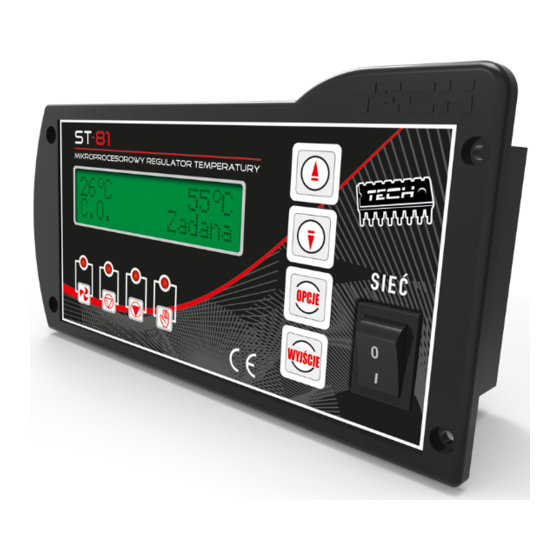
- Page 4 Przycisk PLUS Przycisk MINUS Przycisk wejścia Przycisk powrotu do podmenu, z menu, zatwierdzania anulowania Wyłącznik Nadmuch ustawień Pompa CO Pompa CWU Praca ręczna ustawień sieciowy...
-
Page 5: Description
Each thermo regulator should be set up in accordance with specific needs, basing on the type of fuel used and the type of the boiler. TECH does not take any responsibility for incorrect set up of the thermo regulator - 5 -... - Page 6 ST-81 – USER'S MANUAL I.a) Basic Terms Fire up – The cycle begins when you activate the fire up function in the controller's menu and is active until central heating boiler temperature reaches 40 C (the default fire-up threshold), on condition that the temperature does not drop below this value for 2 minutes (the default fire-up time).
-
Page 7: Functionality Of The Thermo Regulator
TECH II. Functionality of the regulator This chapter describes the functionality of the thermo regulator, means of changing the settings and moving around in the menu. II.a) Main Page set B During normal operation of the thermo regulator (in only CH mode) -
Page 8: Ii.b) Fire Up Sequence
ST-81 – USER'S MANUAL display. This function allows the user to safely operate the boiler. If the fan is turned on it is forbidden to open the furnace door. This setting allows to temporarily switch off the fan at any time e.g. during feeding fuel. - Page 9 TECH Naciśnięcie OPCJE załącza / wyłącza alarm. - 9 -...
-
Page 10: Ii.d) Pumps' Switch On Temperature (Ch And Hcw)
ST-81 – USER'S MANUAL HCW PUMP alarm II.d) Pumps (CH and HCW) switch on temperature Manual operation Pumps switchon temp Pumps switchon temp This option is used in order to set the switch on temperature of the CH and HCW pump (it is measured in the boiler). If the temperature increase above the set level the pumps will switch on. -
Page 11: Ii.f) Hcw Hysteresis
TECH II.f) HCW hysteresis Boiler hysteresis CH temp HCW hysteresis hysteresis This option can be used to set the value of the hysteresis of the boiler set temperature. It is the difference between the set temperature (that is the boiler... -
Page 12: Ii.h) Modes Of Operation
ST-81 – USER'S MANUAL HCW pump temp Modes of oper. A proper symbol for each operation mode is shown in the lower, right corner of the display. Depending on the mode of operation a specific letter is displayed: ) – house heating, ) –... -
Page 13: Ii.h.3) Parallel Pumps
TECH H.C.W. hysteresis); then, the C.H. pump is shut off and the H.C.W. pump is activated. In this mode, the fan is operated as long as the temperature is below 62°C to prevent the boiler from overheating. The hot consumption water priority function consists in that the consumption water is heated up before heating up water in radiators. -
Page 14: Ii.h.4) Summer Mode
ST-81 – USER'S MANUAL the HCW temperatures screen for a few moments. temperature changed with buttons After few seconds the display will return to its previous state. ATTENTION: In this mode, a non-return valve should be fitted to maintain different temperatures in the water heater and in the house. -
Page 15: Ii.i) Room Regulator
CH temp Room regulator ST-81 thermo regulator allows a room regulator to be connected in the system. In this mode the thermo regulator is being controlled by the room regulator and does not take into account the temperature set on thermo regulator main unit. -
Page 16: Ii.l) Language
ST-81 – USER'S MANUAL II.l) Language c 23 c 50 Suspension pause Polski * HCW Set Language choice English This function allows the user to change the language version of the thermo regulator II.m) Factory settings c 23 c 50 Const. -
Page 17: Iii.b) Automatic Sensor Check
TECH the alarm will be deactivated. If the sensor is damaged or overheated, the fan is disabled. Automatic sensor check III.b) In case when the CH temperature sensor is missing or damaged an alarm is activated, which additional reports the fault on the display e.g.:... -
Page 18: Iii.d) Fuse
Higher current ratings may cause damage to the controller. IV. Maintenance Before and during the heating season, the ST-81 controller should be checked for condition of its cables. You should also check if the controller is properly mounted and clean it if dusty or dirty. It is advisable to measure grounding parameters for the motors (central heating pump, hot consumption water pump and fan). -
Page 19: V.a) Cable Connection Diagram For Controller
TECH V.a) Cable Connection Diagram for Controller Pay special attention to cable connections during assembly. Especially, the ground wire should be connected properly. We are committed to protecting the environment. Manufacturing electronic devices imposes an obligation of providing for environmentally safe disposal of used electronic components and devices. -
Page 21: Table Of Contents
TECH Contents I. Description.......................5 II. Functionality of the thermo regulator..............7 II.a) Main Page......................7 II.b) Fire up sequence.....................7 II.c) Manual operation.....................8 II.d) Pumps' switch on temperature (CH and HCW)..........9 II.e) Hysteresis of the boiler..................9 II.f) HCW hysteresis....................10 II.g) Blow force .....................10 II.h) Modes of operation..................11... - Page 22 ST-81 – USER'S MANUAL - 22 -...
Need help?
Do you have a question about the ST-81 and is the answer not in the manual?
Questions and answers