Table of Contents
Advertisement
Quick Links
Advertisement
Table of Contents

Related Manuals for Mindray BeneFusion VP3 Vet


Summary of Contents for Mindray BeneFusion VP3 Vet
- Page 1 BeneFusion VP3 Vet Infusion Pump Operator’s Manual...
- Page 3 © Copyright 2018-2019 Shenzhen Mindray Scientific Co., Ltd. All rights reserved. Release date: March 2019 Revision: 4.0...
- Page 4 Scientific) owns the intellectual property rights to this product and this manual. This manual may refer to information protected by copyrights or patents and does not convey any license under the patent rights of Mindray Scientific, nor the rights of others.
- Page 5 Mindray Scientific or repairs by people other than Mindray Scientific authorized personnel.
- Page 6 Preface Manual Purpose This manual contains the instructions necessary to operate the product safely and in accordance with its function and intended use. Observance of this manual is a prerequisite for proper product performance and correct operation and ensures animal and operator safety. This manual is based on the maximum configuration and therefore some contents may not apply to your product.
-
Page 7: Table Of Contents
Contents 1 Safety ........................1-1 1.1 Safety Information ....................1-1 1.1.1 Warnings ....................1-2 1.1.2 Cautions ....................1-4 1.1.3 Notes .......................1-5 1.2 Equipment Symbols ....................1-5 2 Overview ........................2-1 2.1 Description ......................2-1 2.1.1 Intended Use ...................2-1 2.1.2 Contraindications ..................2-1 2.1.3 Appearance, Parts and Features ............2-1 2.2 Host ........................2-2 2.2.1 Front View ....................2-2 2.2.2 Front View with the Door Opened ............2-4... - Page 8 4.2.2 Load the Infusion Set ................4-2 4.2.3 Change the Infusion Set ................4-4 4.2.4 Change the Infusion Bottle (Bag) ............4-4 4.2.5 Select Infusion Set Brand ................4-4 4.2.6 Parameter Memory Function..............4-5 4.2.7 Select Infusion Mode ................4-5 4.2.8 Purge Air ....................4-5 4.2.9 Set Infusion Parameters ................4-6 4.2.10 Infusion ....................4-6 4.2.11 Infusion Pause ..................4-7 4.2.12 BOLUS ....................4-7...
- Page 9 7.5 Data Export ......................7-3 8 Alarms ........................8-1 8.1 Alarm Level ......................8-1 8.2 Alarm Types ......................8-1 8.2.1 Multi-level Alarm Rules ................8-2 8.3 Alarm Handling Rules ..................8-2 8.4 Alarm Countermeasures ..................8-3 9 Battery ........................9-1 9.1 Battery Performance Optimization ..............9-2 9.2 Check the Battery ....................9-2 9.3 Battery Recycling....................9-3 10 Preservation and Sanitation ................
- Page 10 B.1 EMC ........................B-1 B.2 Radio Regulatory Compliance ................B-7 C Alarm Information ....................C-1 D Symbols and Terms .................... D-1 D.1 List of Units ......................D-1 D.2 List of Symbols ....................D-2 D.3 List of Terms ....................... D-2 D.4 List of Unit Conversion ..................D-3 E Toxic and Hazardous Substances or Elements ..........
-
Page 11: Safety
Safety 1.1 Safety Information WARNING Indicates a potential hazard or unsafe practice that, if not avoided, could result in death, serious injury or damage to product/property. CAUTION Indicates a potential hazard or unsafe practice that, if not avoided, could result in minor personal injury, product malfunction or damage to product/property. -
Page 12: Warnings
1.1.1 Warnings WARNING Device, cables and accessories must be inspected before use to guarantee their normal and safe operation. This equipment can only be connected to the socket with ground protection. Please adopt a rechargeable battery instead of the socket as the power supply if the socket is not provided with a ground lead. - Page 13 Mindray Scientific is not responsible for infusion performance (such as accuracy, air bubble and pressure) and relevant alarm function of the infusion pump.
-
Page 14: Cautions
1.1.2 Cautions CAUTION Use the accessories specified in this Operator’s Manual to guarantee the animal’s safety. When this infusion pump and its accessories exceed their service life, they must be disposed of in accordance with local statutes or hospital regulations. -
Page 15: Notes
1.1.3 Notes NOTE Install the equipment in a position where it can be easily accessed for inspection, operation and maintenance. Keep this Operator’s Manual near to the equipment for future ease of reference. The software was developed in compliance with IEC62304. The possibility of hazards arising from software errors is minimized. - Page 16 Move left Move right Caution Recovery/recyclable Wireless modules Non-ionizing work in order electromagnetic radiation Input/output Night mode DEFIBRILLATION-PROOF Drop sensor interface TYPE CF APPLIED PART Date of manufacture Manufacturer THIS WAY UP Keep dry Fragile, handle with STACKING LIMIT BY care NUMBER Authorized...
-
Page 17: Overview
Overview 2.1 Description 2.1.1 Intended Use The infusion pump is used in conjunction with the infusion set to control the dose of liquid infused into the animal’s body. The pump may also be used for blood transfusion. For this therapy only use disposables dedicated and labelled for transfusion. -
Page 18: Host
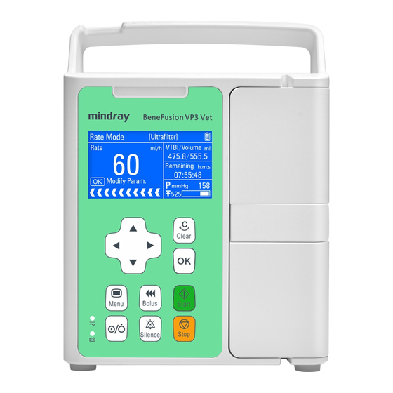
2.2 Host 2.2.1 Front View 1. Alarm light The alarm light indicates different alarm levels in different colors and flash frequencies, please refer to Chapter 8 Alarms for details . 2. Display Used for displaying infusion parameters and relevant content. 3. - Page 19 7. AC/DC indicator light On: The pump is connected to an AC/DC power supply (including shutdown). Off: The pump is not connected to an AC/DC power supply. 8. Battery indicator light Steady green indicates that the battery is charging. ...
-
Page 20: Front View With The Door Opened
2.2.2 Front View with the Door Opened 1. Liquid check clip button 2. Liquid check clip 3. Infusion set slot... -
Page 21: Rear View
2.2.3 Rear View 1. Multifunction interface with the following functions: DC power supply port RS232 interface Nurse call interface 2. AC power supply port Connection for the AC power cord. 3. Drop sensor interface (Drop sensor is optional) 4. -
Page 22: Screen Display
2.3 Screen Display This infusion pump has a monochrome LCD screen. The display information comprises three main parts: 1. Title bar Displays current infusion mode, drug information, alarm information, battery icon, and etc. 2. Parameter area Displays every parameter and the parameter value of the current screen. 3. -
Page 23: Installation And Setting
Installation and Setting 3.1 Installation WARNING Equipment assembly and refit (including correct protective grounding connection) during life period must be carried out by maintenance technicians whom are trained and licensed by the manufacturer, and evaluated according to the specified IEC60601-1. Please contact the company if you have any queries. -
Page 24: Out Of Box Audit (Ooba)
3.1.1 Out of Box Audit (OOBA) Please check the packing case carefully before opening the box. If there is any damage, please contact the distributor or manufacturer immediately. Please carefully remove the equipment and its accessories from the packaging in a correct manner, and inspect them against the packing list. -
Page 25: Mount The Clamp
WARNING Please use only when the operating environment meets the requirements specified above. Otherwise, the pump's performance will not match the technical specifications in A Product Specifications. Device failure and other unexpected consequences may also result. 3.1.3 Mount the Clamp 3.1.3.1 Standard Pole Clamp 1. -
Page 26: Fix Benefusion Ds3 Infusion Supervision System (Optional)
3.1.4 Fix BeneFusion DS3 Infusion Supervision System (Optional) The device can be located in the BeneFusion DS3 Infusion Supervision System. NOTE All components of the system are suitable for use in animal environment. Removing power cord is to disconnect equipment from power supply. Please ensure suitable clearance around the System to facilitate connect and remove power cord. -
Page 27: Install And Operate The Drop Sensor (Optional)
Connect one end of the power cord to the device's AC power supply port, and check that internal and surrounding AC power supply port without liquid drug and other residues. Insert the other end of the power cord into the three-plug connector. Check that the AC/DC indicator light is on. - Page 28 1. Firmly insert the signal line of drop sensor into the drop sensor interface of the pump. 2. Clip the drop sensor to the drip chamber, making sure that the drop sensor is above the surface of the liquid. 3. Press to start the infusion.
-
Page 29: Conventional Settings
3.2 Conventional Settings This chapter only introduces the general settings for the infusion pump, please refer to other relative chapters for parameters and other feature settings. 3.2.1 Adjust Alarm Sound Volume Select [Main Menu]→[System Options]→[Sound Volume]. Select [Sound Volume]: 1-8.1 for the lowest volume; 8 for the highest volume. -
Page 30: Restore Factory Default
3.3 Restore Factory Default During operation, you may change some settings in some situations. However, the changes may not be appropriate or correct, especially when animal or infusion set brands are changed. Therefore, you should restore to the default factory settings during operation according to actual needs, to guarantee that each configuration of the infusion pump is applicable for clinical use. -
Page 31: Basic Operation
Basic Operation 4.1 Infusion Flow Chart Turn pump on Press to activate and turn on the pump, the pump will run start-up checks and display the start-up screen; Load infusion set Please refer to 4.2.2 Load the Infusion Set; Select according to the infusion set brand currently Select brand being used;... -
Page 32: Operational Procedures
4.2 Operational Procedures 4.2.1 Turn on the Pump To turn on the device, follow this procedure: Perform a safety inspection referring to 11.1 Inspection before turning on the pump. Press , the system will initiate the self-test and the screen will display the [System Self-test] interface: ... - Page 33 Load infusion set according to the following method: 2. Pull the free flow clamp button upward left, 1. Pull the door holder and open the door. and open the free flow clamp. 4. Close the door, the interface will enter [Set 3.
-
Page 34: Change The Infusion Set
WARNING The infusion set should be firmly loaded into the slot, and not jutting on the outside of the slot. Before using this infusion pump, the infusion pump, infusion set and other accessories should be loaded correctly. 4.2.3 Change the Infusion Set Follow the steps below to change the infusion set: 1. -
Page 35: Parameter Memory Function
4.2.6 Parameter Memory Function In clinical treatments, the medical staffs need to initiate the infusion as soon as possible during emergency situations, infuse the liquid drug into the animal's body in the shortest time possible, and set the detailed parameters later during infusion. 1. -
Page 36: Set Infusion Parameters
NOTE Purge rate can not be changed. [Air in line] and [Accumulate air] alarms will not be triggered during purge. 4.2.9 Set Infusion Parameters Under each infusion mode, users can set infusion parameters by pressing 4.2.10 Infusion When ready, connect the infusion set to the animal. Press to start the infusion, and the screen will display the running icon. -
Page 37: Infusion Pause
4.2.11 Infusion Pause During infusion, if changing the drug liquid or infusion set is needed, press enter the [Pause] interface to stop the infusion. On the [Pause] screen, press to return to the parameters setting interface, and you can modify infusion parameters;... -
Page 38: Complete
4.2.14 Complete When [VTBI] is not set during the infusion and infusion is completed, if drop sensor is installed and the switch of [Drop sensor] is on, the [Empty] alarm will be triggered. When [VTBI] is set during the infusion and the remaining infusion time is close to the [Time Near End] set by the users, the [Time Near End] alarm will be triggered. -
Page 39: Infusion Mode
Infusion Mode 5.1 Rate Mode Unit of Rate (ml/h) Unit of Rate (gtt/min) Mode Parameters Parameter Range Unit of Rate (ml/h): 0.1-2000ml/h Rate Unit of Rate (gtt/min): 1-(400*Drip/60) gtt/min Rate Mode VTBI 0.1-9999ml Time 00:00:01-99:59:59 h:m:s Please refer to 6.6 Drip Setting for the settings of the unit of “gtt/min”. -
Page 40: Time Mode
5.2 Time Mode Unit of Rate (ml/h) Unit of Rate (gtt/min) Mode Parameters Parameter Range Time 00:00:01-99:59:59 h:m:s VTBI 0.1-9999ml Time Mode Rate Same as Rate Mode 5.3 Body Weight Mode 1. Select [Main Menu]→[User Maintenance]→Input User Maintenance Password→[BW Mode Configuration]. - Page 41 Conc. Configuration: Drug Amount and Volume Configuration: Mode Parameters Parameter Range Weight 0.1-300.0 kg/0.2-660.8 lb Drug amt. 0.1-99999 ng, μg, mg, g, mU, U, kU, EU, mmol, mol, kcal, mEq Drug amt. unit Volume 0.1-9999ml Conc. 0.1-9999 ng/ml, μg/ml, mg/ml, g/ml, mU/ml, U/ml, kU/ml, Conc.
-
Page 42: Sequential Mode
5.4 Sequential Mode Several different sequences (parameter group) can be set in Sequential Mode, and the infusion pump infuses according to the set infusion sequence. 5 sequences can be set in this mode. The rate of the current sequence can be changed during the operation process. -
Page 43: Setting Parameters
Setting Parameters 6.1 KVO KVO (Keep Vein Open) means to keep the vein open, during which the infusion pump continues infusion at a very low rate after finishing the infusion in order to prevent blood backflow or vascular occlusion. Select [Main Menu]→[General Options]→[KVO Rate]. Select [KVO Rate]: 0.1-5.0ml/h is adjustable. -
Page 44: Occlusion Pressure
6.3 Occlusion Pressure Occlusion pressure is adjustable, which can meet the requirements for occlusion pressure of different animals during infusion. Pressure in the infusion tube can be measured by the built-in pressure sensor, pressure can be calculated by the internal CPU, which is compared with the preset occlusion alarm threshold. -
Page 45: Dynamic Pressure Scanning (Dps)
6.3.3 Dynamic Pressure Scanning (DPS) During the infusion, the bottom-right corner of the Run screen demonstrates real-time pressure changes of the animal, in order to find the tube occlusion at an earlier time and to prevent the occurrence of further complications. 6.3.4 Automatic Pressure Release Function (Anti-Bolus) When occlusion occurs, infusion will stop and the [Occlusion] alarm will be triggered. -
Page 46: Key Lock Function
6.7 Key Lock Function When locked, an icon in the upper-right corner of the screen emerges. The following are two ways for automatic lock and manual lock: Automatic Lock: Select [Main Menu]→[General Options]→[Auto-lock Time]. Select [Auto-lock Time]: Off, 1-5min. After a specific time is set during the running state, and if there is no operation or high-level alarm within the set Auto-lock time, the key board will be auto-locked. -
Page 47: Set The Sensitivity Of Empty Bottle Alarm
Note: Please ensure that at least one “Infusion Set” to be selected. Brand and model of compatible infusion sets: Type Brand and Model specification Regular BOON A2 20drops Regular B.Braun Intrafix Safeset 20drops WARNING It is recommended that infusion pump is used with high elastic tube. If you are not sure whether the tube is high elastic tube, please contact us for tube test. -
Page 48: Other Functions
Other Functions 7.1 History Record The infusion pump when in use will produce some key data stored in [History Record], providing foundation for the treatment review and maintenance review at a later period. The attribute of recording events includes action, time and description. A record is created once an event occurs. -
Page 49: Wireless Networking (Optional)
Alarm level: Three options: [High], [Medium] and [Low].The system sends nurse call signals according to the alarm at the selected alarm level or above. WARNING Non-medical personnel are forbidden to modify the nurse call setting. The nurse call function must be used in conjunction with a special cable. NOTE ... -
Page 50: Data Export
pump and CIMS depends on whether the network connection is successful, operators are unable to observe the operation status of the pump in real time when the communication is interrupted. After the network connection settings of the pump and CIMS are modified, operators shall reset the network connection as required in the manual to ensure the communication of the pump and CIMS are restored. -
Page 51: Alarms
Alarms The alarm is used in order to alert the medical staff by means of sound and light when abnormal situations occur during the infusion procedure which can lead to infusion changes or when the infusion of the animal cannot continue due to the unexpected breakdown or pause/delay of the infusion pump. -
Page 52: Multi-Level Alarm Rules
8.2.1 Multi-level Alarm Rules When several alarms occur simultaneously, the alarms proceed according to the following rules: When several alarms at different levels occur, the visible alarms and audible alarms are consistent with the highest-level alarms. When several alarms at different levels occur, only the highest-level alarm is displayed, and after it is cancelled, the lower-level alarm will then be displayed. -
Page 53: Alarm Countermeasures
8.4 Alarm Countermeasures WARNING When an alarm is triggered, the animal's condition should be checked firstly and operation should only be allowed to proceed after the reason for the triggering of the alarm is ruled out. When an alarm is triggered, please follow these steps and take appropriate action: 1. -
Page 54: Battery
Battery WARNING The battery can not be disassembled. The battery should be changed by maintenance staff designated by the company only. Changing the battery incorrectly or changing battery by personnel who has not received suitable training may cause such danger as overtemperature, fire or explode. -
Page 55: Battery Performance Optimization
The power supply by the battery can only be sustained for a limited period of time. The [No Battery] alarm will be triggered when the battery voltage is too low, and red alarm light will flash. The alarm will continue within the remaining time of the battery’s electric quantity and cannot be paused. -
Page 56: Battery Recycling
NOTE The lifespan of the battery depends on how frequently it is used and on how long it has been used, battery capactiy decreases with increase in charging and discharging times. If the maintenance and storage of the battery is appropriate, the lifespan of the Lithium battery is no less than 300 times of full charging and discharging. -
Page 57: Preservation And Sanitation
Preservation and Sanitation The pump must be cleaned or disinfected using the materials and methods listed in this section. The manufacturer will not be responsible for any damage or accident caused by cleaning and disinfection using other materials and methods. The manufacturer shall not be held responsible for the efficacy of the following chemicals or methods for infection control. -
Page 58: Disinfection
To clean your equipment, follow these rules: Turn off the pump and disconnect the AC power source line. Wipe the display screen after soft cotton balls absorb an appropriate amount of detergent. Use a piece of soft cloth which absorbs a modest amount of cleaning agent to wipe the surface of the device. -
Page 59: Maintenance
Maintenance WARNING To avoid electric shock, stop using the device if you find its housing has signs of broken. Contact the service personnel for help in that case. The hospital or medical facility using this infusion pump must set up a comprehensive maintenance plan. -
Page 60: Maintenance Plan
11.2 Maintenance Plan The following tasks must be conducted by professional maintenance personnel approved by the company. Please contact the company if the following maintenances are needed. Must clean and disinfect the device before the test or maintenance. Inspection/Maintenance Items Frequency Once every two years. -
Page 61: Accessories
Accessories WARNING Use the accessories specified in this chapter only. Other accessories may cause damage to this infusion pump, or cannot reach the specification in this manual. Please do not replace an accessory if its package or itself is damaged. Materials 0020-20-12522 009-002755-00... - Page 62 Cable specifications: Item Length (m) Whether shielded Comments Power cord With magnetic DC cable ring With magnetic Nurse call cable ring Serial port communication cable NOTE This Operator’s Manual describes the most complete functional configuration of the system. The device you are using may not have some of the settings or functions described herein.
-
Page 63: A Product Specifications
Product Specifications A.1 Safety Specifications A.1.1 Product Classification Classifications of this infusion pump according to the IEC60601-1 standard are as follows: Safety Components Host Type of protection Class I against electrical shock Degree of protection Type CF defibrillation proof against electrical shock Ingress Protection IP34 Degree of safety of... -
Page 64: Operating Environment
A.1.2 Operating Environment Work environment Temperature 5-40º C Humidity 15-95%, non-condensing Atmospheric pressure 57-106 kPa Storage environment Temperature -20-60 º C Humidity 10-95%, non-condensing Atmospheric pressure 50-106kPa Storage conditions Corrosive-free and ventilated indoors AC Power Supply Voltage 100-240V~ Frequency 50/60Hz Current 0.40-0.14A Fuse... -
Page 65: Hardware Specifications
A.3 Hardware Specifications A.3.1 Display Display Type Monochrome LCD Size (diagonal) 3 inches Differentiation 128 pixels A.3.2 Battery Internal battery No. of batteries 1 (standard) or 2 (optional) Battery type Lithium battery Shutdown delay At least 30 mins (new battery, after the first low battery alarm) Battery voltage 7.2V Battery capacity... -
Page 66: Auditory Indicator
A.3.4 Auditory Indicator Produce an alarm, the sound pressure is 55-77 dB(A) and key Speaker beep; Support multi-level volume functions; The alarm sound meets the requirements of the IEC60601-1-8. A.3.5 External Ports Ports AC power supply One AC power supply port port Multifunction One multifunction interface with the following functions:... -
Page 67: Specifications
A.4 Specifications Parameters Specifications Factory Default Infusion set used in conjunction with infusion pump should meet the Infusion set requirements of ISO 8536-4:2004 standard Infusion equipment for medical use— Part 4: Infusion sets for single use, gravity feed, MOD Unit of Rate (ml/h): 0.1-2000ml/h, the minimum increment is 0.1ml/h Unit of Rate (gtt/min): 1-(400*Drip /60) gtt/min, the minimum increment is... - Page 68 Mode, Sequential Mode 4 Levels are adjustable, respectively are: 150± 125mmHg (20.0± 16.7kPa), 300± 125mmHg (40.0± 16.7kPa), 525± 125mmHg (70.0± 16.7kPa), 900± 180mmHg (120.0± 24.0kPa). Maximum occlusion pressure is about 1080mmHg. Note 1: The detected pressure of the infusion system (infusion pump and Pressure 525mmHg infusion set) is affected by inner and...
- Page 69 Max. Rate 0.1-2000ml/h 2000ml/h Drip:10-60 gtt/ml 20gtt/ml Drip Setting gtt/min: On, Off Drip Abnormal On, Off Empty High, Low Sensitivity Auto-lock Time Off, 1-5min, step for 1min Reminder Time Off, 1-5min, step for 1min 2min Weight Unit kg, lb Sound Volume Brightness Contrast 150-220...
- Page 70 infusion set) is affected by inner and outer diameter, material, elasticity of the infusion set and other factors. Therefore, infusion sets of different brand and model may differ in the infusion accuracy. Note 2: The above declared infusion accuracy is based on BOON A2 and B.Braun Intrafix Safeset infusion sets, temperature of 20±...
-
Page 71: A Reference Table Showing Occlusion Alarm Delay And Possible Dose
A.5 A Reference Table Showing Occlusion Alarm Delay and Possible Dose Occlusion Pressure Rate Time of Occlusion Alarm (mmHg) (ml/h) (hh:mm:ss) 02:52:16 00:02:19 00:00:30 17:51:50 00:17:12 00:02:00 Rate Pressure Setting Bolus Volume (ml) (ml/h) <0.1 <0.15 NOTE Test conditions: ... -
Page 72: Infusion Accuracy Curve And Trumpet Curve
A.6 Infusion Accuracy Curve and Trumpet Curve The following typical infusion accuracy table expresses performance after infusion has started and infusion fluctuations occurring within a certain period of time after normal infusion flow volumes have been reached. The infusion accuracy table is for reference only, detailed infusion accuracy curve is in accordance with the final device. - Page 73 Unit of Rate (ml/h) A-11...
- Page 74 Unit of Rate (gtt/min) Sampling rate: 20gtt/min Sampling interval: △t =1min Test period: t =120mins Infusion rate: Q (gtt/min) Sampling rate: 20gtt/min Sampling interval: △ t =1min Observation windows: p△ t =2, 5, 11, 19, 31mins Maximum deviation over the course of a full observation window: Ep(Max) (%) Minimum deviation over the...
-
Page 75: B Emc And Radio Regulatory Compliance
EMC and Radio Regulatory Compliance B.1 EMC The device meets the requirements of IEC 60601-1-2:2014. NOTE Use of accessories, transducers and cables other than those specified or provided by the manufacturer of this device could result in increased electromagnetic emissions or decreased electromagnetic immunity of this device and result in improper operation. - Page 76 Guidance and Declaration - Electromagnetic Emissions The device is intended for use in the electromagnetic environment specified below. The customer or the user of the device should assure that it is used in such an environment. Emission test Compliance Electromagnetic environment - guidance Conducted and radiated Group 1 The device uses RF energy only for its...
- Page 77 If the device is operated within the electromagnetic environment listed in Table Guidance and Declaration —Electromagnetic Immunity, the system will remain safe and provide the following essential performance: Operating mode Accuracy Function Protection against UNINTENDED BOLUS volumes ...
- Page 78 power supply or a battery. RATED power 30 A/m 30 A/m Power frequency frequency 50 Hz / 60 Hz 50 Hz / 60 Hz magnetic fields should magnetic fields be at levels IEC 61000-4-8 characteristic of a typical location in a typical commercial or hospital environment.
- Page 79 9 V/m 9 V/m electromagnetic site survey , should 704–787 MHz, be less than the compliance level in 5100–5800 each frequency range Interference may occur in the vicinity of equipment marked with the following symbol: Note 1: At 80 MHz and 800 MHz, the higher frequency range applies. Note 2: These guidelines may not apply in all situations.
- Page 80 Recommended Separation Distances between Portable and Mobile RF, Communications Equipment and This Equipment The equipment is intended for use in an electromagnetic environment in which radiated RF disturbance are controlled. The customer or the user of the device can help prevent electromagnetic interference by maintaining a minimum distance between portable and mobile RF communications equipment (transmitters) and the device as recommended below, according to the maximum output power of the communication equipment.
-
Page 81: Radio Regulatory Compliance
B.2 Radio Regulatory Compliance RF Parameter Radio devices IEEE 802.11b/g/n (2.4GHz Wi-Fi) Operating frequency 2412MHz to 2472MHz Modulation mode DSSS, OFDM ≤20dBm Output power The radio device used in this product is in compliance with the essential requirements and other relevant provisions of Directive 2014/53/EU. -
Page 82: C Alarm Information
Alarm Information This chapter presents the alarm information of the infusion pump. Prompt information for operation guidance will not be presented in this chapter. The table shows the appropriate countermeasures for each piece of information related to alarm triggering. If the problem still exists after operating according to the countermeasures, please contact the company. - Page 83 Alarm Alarm Reason Countermeasure Information Level 1. Press to cancel alarm. 2. Or alarm is cancelled Infusion volume reaches the when reach the KVO [VTBI Complete] High preset VTBI. infusion time. 3. Or press confirm KVO infusion to cancel alarm. KVO infusion has run for 30 Press to cancel...
- Page 84 Alarm Alarm Reason Countermeasure Information Level Pump is in standby mode [Standby Time Press Medium and standby time is Expired] completed. cancel alarm. 1. Operate the pump (except press ) to The infusion pump performs no operation during the set cancel alarm.
- Page 85 Alarm Alarm Reason Countermeasure Information Level over Wi-Fi, the network BeneFusion CS5 Infusion communication is abnormally Supervision System. interrupted for 3 minutes. After the alarm is triggered, infusion of the pump will not be influenced, and the pump continues infusion. 1.
-
Page 86: D Symbols And Terms
Symbols and Terms D.1 List of Units Abbreviation Meaning ampere ℃ centigrade centimeter decibel gram hour hertz inch inch kilo kilogram kilopascal litre pound meter milligrams minute milliliter millimeters mmHg millimeters of mercury second μg Microgram volt volt ampere watt... -
Page 87: List Of Symbols
D.2 List of Symbols Symbols Meaning minus percent Per; divide; or ~ power plus + = equal to < less than > greater than ≤ less than or equal to ≥ greater than or equal to plus or minus ± ×... -
Page 88: List Of Unit Conversion
Abbreviation Meaning European Economic Community Electromagnetic compatibility Electromagnetic interference C2H4O Intensive Care Unit Identification International Electrotechnical Commission IEEE Institute of Electrical and Electronic Engineers International organization for Standardization Keep vein open Light emitting diode Maximum Medical Device Directive Minimum Magnetic resonance imaging Not applied NICU Newborn Intensive Care Unit... -
Page 89: E Toxic And Hazardous Substances Or Elements
Toxic and Hazardous Substances or Elements Cr(VI) PBDE Name of the Parts Cr(VI) PBDE ○ ○ ○ ○ ○ ○ Front housing ○ ○ ○ ○ ○ ○ Back housing Device ○ ○ ○ ○ ○ ○ Keys housing ○ ○... -
Page 90: F Declaration Of Conformity
Declaration of Conformity P/N: 046-013101-00 (4.0)
Need help?
Do you have a question about the BeneFusion VP3 Vet and is the answer not in the manual?
Questions and answers