Table of Contents
Advertisement
Quick Links
Advertisement
Table of Contents

Related Manuals for Dell W-7205 Series


Summary of Contents for Dell W-7205 Series
- Page 1 Dell Networking W-7205 Controller Installation Guide...
- Page 2 ® System . Dell™, the DELL™ logo, and PowerConnect™ are trademarks of Dell Inc. All rights reserved. Specifications in this manual are subject to change without notice. Originated in the USA. All other trademarks are the property of their respective owners.
-
Page 3: Table Of Contents
Serial Console Port Serial Console Port Adapter Micro-USB Console Port Micro-USB Driver Management Port Power, Status, and Peered LEDs LCD Panel LCD Menu Disabling the LCD Screen CPU Module Power Supply Dell Networking W-7205 Controller | Installation Guide Contents | 3... - Page 4 Disconnecting an LC Fiber Optic Cable Removing an SFP/SFP+ Module Specifications, Safety, and Compliance W-7205 Specifications Physical Power Supply Specifications Operating Specifications Storage Specifications Safety and Regulatory Compliance Regulatory Model Name Electromagnetic Interference 4 | Contents Dell Networking W-7205 Controller | Installation Guide...
- Page 5 Europe Japan VCCI Taiwan (BSMI) South Korea EU Regulatory Conformance Battery Statements Proper Disposal of Dell Equipment Waste of Electrical and Electronic Equipment China RoHS European Union RoHS India RoHS Dell Networking W-7205 Controller | Installation Guide Contents | 5...
-
Page 7: Preface
Preface This document describes the hardware features of the Dell Networking W-7205 Controller. It provides a detailed overview of the physical and performance characteristics of the controller and explains how to install the controller and its accessories. Guide Overview W-7205 Controller on page 9 provides a detailed hardware overview of the W-7205 controller and its components. -
Page 9: W-7205 Controller
8192 2 x 10GBASE-X NOTE: The W-7205 controller requires Dell Networking W-Series ArubaOS 6.4.3.1 or later version. Packaging Checklist NOTE: Inform your supplier if there are any incorrect, missing, or damaged parts. If possible, retain the carton, including the original packing materials. -
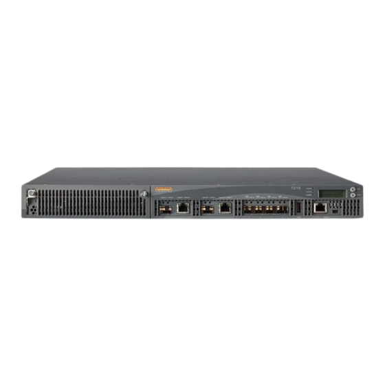
Page 10: W-7205 Components
Dell Safety, Environment, and Regulatory Information (printed) Dell Warranty and Support Information (printed) Dell Software License Agreement (printed) NOTE: Optional accessories are available for use with the Dell W-7205 controller and are sold separately. Contact your Dell sales representative for details and assistance. W-7205 Components This section introduces the different components of the W-7205 controller, and specifies their locations in the controller. -
Page 11: Dual-Media Ports
Figure 3 illustrates the CAT-5 pin-out on an RJ-45 connector. The CAT-5 pin-out pairs the following pins on a 10/100/1000BASE-T Gigabit Ethernet port: 1/2, 3/ 6, 4/5, and 7/8. Dell Networking W-7205 Controller | Installation Guide W-7205 Controller | 11... -
Page 12: 1000Base-X (Sfp) Ports
Table 6: 1000BASE-X Port LEDs Function LCD Mode Indicator Status LINK/ACT Link status Link status Green (Solid) Link established Green (Blinking) Port is transmitting or receiving data No link 12 | W-7205 Controller Dell Networking W-7205 Controller | Installation Guide... -
Page 13: 10Gbase-X Ports
Table Table 7: 10GBASE-X Port LEDs Function LCD Mode Indicator Status LINK/ACT Link status Green (Solid) Link established Green (Blinking) Port is transmitting or receiving data No link Dell Networking W-7205 Controller | Installation Guide W-7205 Controller | 13... -
Page 14: Sfp/Sfp+ Modules And Dac Cables
Table 8 Table NOTE: Other non-approved third-party optics or DAC cables are not tested or supported by Dell on controllers; therefore, Dell does not guarantee their proper functionality when used with Dell controllers. NOTE: SFP/SFP+ Modules and DAC cables are sold separately. Contact your Dell sales representative for details and assistance. -
Page 15: Usb Interface
The communication settings for the console port are shown in the following table: Table 10: Console Terminal Settings Baud Rate Data Bits Parity Stop Bits Flow Control 9600 None None Dell Networking W-7205 Controller | Installation Guide W-7205 Controller | 15... -
Page 16: Serial Console Port Adapter
Micro-USB Driver To use the Micro-USB console port, install the Micro-USB driver on the system that will manage the controller. The driver is available for download on download.dell-pcw.com under Tools & Resources . Management Port The W-7205 controller is equipped with a 10/100/1000BASE-T Gigabit Management (RJ-45) port on the front (see Figure 4). -
Page 17: Power, Status, And Peered Leds
LED mode: DPX Duplex– Displays the duplex descriptions of the LED behavior of mode of the port each mode. LED mode: SPD Speed– Displays the speed of the port. Dell Networking W-7205 Controller | Installation Guide W-7205 Controller | 17... -
Page 18: Disabling The Lcd Screen
To disable only the Maintenance menu or one of its sub-menus, enter the Enable mode and use the following CLI commands: (host) #configure terminal (host) (config) #lcd (host) (lcd-menu) #disable menu maintenance ? factory-default halt-system media-eject reload-system upgrade-image upload-config (host) (lcd-menu) #disable menu maintenance upgrade-image ? partition0 partition1 18 | W-7205 Controller Dell Networking W-7205 Controller | Installation Guide... -
Page 19: Cpu Module
The W-7205 controller is equipped with a pre-installed CPU module on the back panel of the controller. NOTE: Do not remove the CPU module unless directed by an authorized Dell technician. The CPU module is not hot-swappable. For LED behavior on the CPU module, see... -
Page 21: Installation
7205 controller ships with an accessory kit that includes the equipment needed to mount the controller in a standard two-post 19-inch Telco rack. CAUTION: Only use the included or Dell specified cables, power cords, AC power supplies, and batteries. The power cord should not be used with other electric equipment than what is specified by Dell. -
Page 22: Selecting A Location
Suitable screwdrivers (not included in the package) NOTE: Some racks require screws that differ from those included with the W-7205 controller. Ensure to have the correct screws before installing the controller. 22 | Installation Dell Networking W-7205 Controller | Installation Guide... -
Page 23: Installation Steps
CAUTION: Each W-7205 controller must have its own mounting equipment. Do not place other networking equipment directly on top of a mounted W-7205 controller. Failure to do so can damage the controller. Dell Networking W-7205 Controller | Installation Guide Installation | 23... -
Page 24: Required Tools And Equipment
3. If the rack requires cage nuts or clip nuts, insert them on the front rails (two per rail, aligned horizontally) 4. Mount the controller in the rack using the four screws for system rack mount (two per bracket) and suitable screwdriver (see Figure 10). 24 | Installation Dell Networking W-7205 Controller | Installation Guide... -
Page 25: Required Tools And Equipment
2. Place the controller on the desired flat table or shelf. Figure 11 Attaching Rubber Feet Wall Mounting An optional accessory kit (SPR-WL2-MNT, must be purchased separately) is available that allows you to mount the W-7205 controller to a wall. Dell Networking W-7205 Controller | Installation Guide Installation | 25... -
Page 26: Required Tools And Equipment
3. Drill the holes and insert wall anchors if the installation requires them. 4. Align the holes of the mounting bracket with the holes drilled in the wall (see Figure 13). 5. Use appropriate screws to secure the controller. 26 | Installation Dell Networking W-7205 Controller | Installation Guide... -
Page 27: Connecting And Disconnecting The Ac Power Cord
2. Insert the coupler end of the AC power cord into the AC power connector. 3. Lower the power cord retaining clip over the AC power cord. The W-7205 controller should now be receiving power. Dell Networking W-7205 Controller | Installation Guide Installation | 27... -
Page 28: Disconnecting The Ac Power Cord
2. Insert the fiber optic cable into the SFP/SFP+ module. Ensure that the latch on the cable faces the top of the SFP/SFP+ module (see Figure 15). 3. Slide the cable into place until a connection is made and an audible click is heard. 28 | Installation Dell Networking W-7205 Controller | Installation Guide... -
Page 29: Disconnecting An Lc Fiber Optic Cable
1. Depress the transceiver handle to release the latch on the cable and simultaneously pull the cable out of the port. Removing an SFP/SFP+ Module To remove an SFP/SFP+ module: 1. Open and release the latch on the SFP/SFP+ module. 2. Pull and remove the module from the port. Dell Networking W-7205 Controller | Installation Guide Installation | 29... -
Page 31: Specifications, Safety, And Compliance
W-Series Safety, Environmental, and Regulatory Information document included with this product. CAUTION: The Dell controllers must be installed by a professional installer. The professional installer is responsible for ensuring that grounding is available and it meets applicable local and national electrical codes. -
Page 32: Regulatory Model Name
This digital apparatus does not exceed the Class A limits for radio noise emissions from digital apparatus as set out in the interference-causing equipment standard entitled “Digital Apparatus,” ICES-003 of the Department of Communications. 32 | Specifications, Safety, and Compliance Dell Networking W-7205 Controller | Installation Guide... -
Page 33: Europe
This product is CE marked according to the provisions of the EMC Directive (2004/108/EC) - CE. Dell, hereby declares that W-7205controller device models are in compliance with the essential requirements and other relevant provisions of Directive (2004/108/EC) – CE. The Declaration of Conformity made under Directive 1999/5/EC is available for viewing on dell.com. -
Page 34: Proper Disposal Of Dell Equipment
Proper Disposal of Dell Equipment Waste of Electrical and Electronic Equipment Dell products at end of life are subject to separate collection and treatment in the EU Member States, Norway, and Switzerland and therefore are marked with the symbol shown at the left (crossed- out wheelie bin). -
Page 35: India Rohs
India RoHS This product complies with RoHS requirements as prescribed by E-Waste (Management & Handling) Rules, governed by the Ministry of Environment & Forests, Government of India. Dell Networking W-7205 Controller | Installation Guide Specifications, Safety, and Compliance | 35... - Page 36 36 | Specifications, Safety, and Compliance Dell Networking W-7205 Controller | Installation Guide...