Table of Contents
Advertisement
Quick Links
Advertisement
Table of Contents

Related Manuals for Dell W-7030


Summary of Contents for Dell W-7030
- Page 1 Dell Networking W-7030 Controller Installation Guide...
- Page 2 VPN client devices constitutes complete acceptance of liability by that individual or corporation for this action and indemnifies, in full, Aruba Networks, Inc. from any and all legal actions that might be taken against it with respect to infringement of copyright on behalf of those vendors. Dell Networking W-7030 Controller | Installation Guide 0511628-02 | February 2015...
-
Page 3: Table Of Contents
Mini-USB Driver ....................... 21 Console Port ..........................21 Serial Console Port Adaptor................... 22 Power Supply ..........................22 Grounding Point ........................22 Kensington Lock ........................22 SFP Modules ............................. 22 Chapter 2 Specifications, Safety, and Compliance................ 23 Dell Networking W-7030 Controller | Installation Guide... - Page 4 Taiwan (BSMI) .......................... 25 Battery Statements ........................25 Proper Disposal of Dell Equipment....................26 Waste of Electrical and Electronic Equipment..............26 European Union RoHS ......................26 India RoHS ..........................26 China RoHS..........................26 Dell Networking W-7030 Controller | Installation Guide...
-
Page 5: Preface
Preface This document describes the hardware features of the Dell Networking W-7030 Controller. It provides a detailed overview of the physical and performance characteristics the controller, and explains how to install the controller and its accessories. Guide Overview Chapter 1, “W-7030 Controller” on page 15 provides a detailed hardware overview of the W-7030 controller ... - Page 6 6 | Preface Dell Networking W-7030 Controller | Installation Guide...
- Page 7 Dell Safety, Environment, and Regulatory Information (printed) Dell Warranty and Support Information (printed) NOTE: Optional accessories are available for use with the W-7030 controller and are sold separately. Contact your Dell sales representative for details and assistance. Dell Networking W-7030 Controller | Installation Guide...
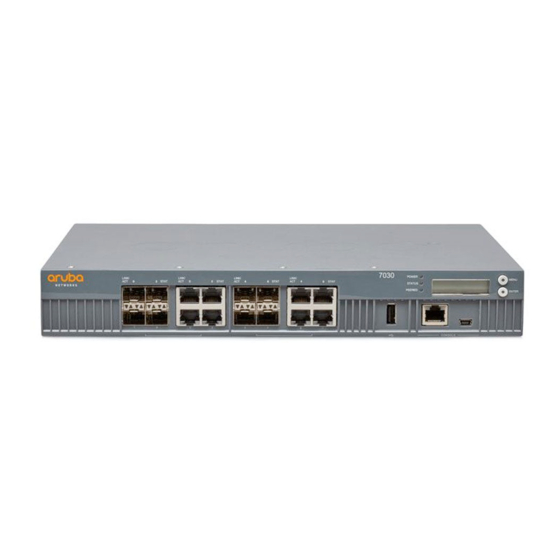
- Page 8 W-7030 Components This section introduces the different components of the W-7030 controller, and specifies their locations in the controller. Figure 8 shows the front panel of the W-7030 controller and Figure 9 shows the back panel of the W-7030 controller.
- Page 9 Grounding point Access Ports The W-7030 controller is equipped with 8 dual-media ports (ports 0 through 7). These ports can utilize either the 1000Base-X or 10/100/1000Base-T connections provided. However, the 1000Base-X fiber connection has priority over the 10/100/1000Base-T copper connection. If a link is detected on the 1000Base-X interface, the 10/100/ 1000Base-T connection will be disabled.
- Page 10 Green (Blinking) Port is transmitting or receiving data No link STATUS Port status Administrative Green (Solid) Port Enabled Port Administratively Disabled Duplex Green (Solid) Full-duplex Speed Green (Solid) 1 Gbps 18 | W-7030 Controller Dell Networking W-7030 Controller | Installation Guide...
- Page 11 Peered Reserved for future use LCD Panel The W-7030 controller is equipped with an LCD panel (see Figure 11) that displays information about the controller’s status, and provides a menu that allows basic operations such as initial setup and reboot. The LCD panel displays two lines of text with a maximum of 16 characters per line.
- Page 12 Exit Maintenance menu. Disabling the LCD Screen By default, the LCD screen is enabled. However, if the W-7030 controller is deployed in a location without physical security, the LCD screen can be disabled through the CLI. When disabled, pushing one of the navigation buttons will only illuminate the LCD screen and display the slot, role, device name, and any alarms.
- Page 13 “LCD Panel” on page 19. Mini-USB Console Connector The W-7030 controller is equipped with one Mini-USB (type B) connector that provides console access for direct local access. See Figure 11 on page 19. If both Mini-USB and RJ-45 Console ports are connected, the Mini-USB connection takes precedence over the RJ-45 Console connection.
- Page 14 NOTE: Dell tests and supports Dell approved optics within Dell controller devices. Non-approved third party optics are not tested or supported; therefore, Dell does not guarantee proper functionality of non-approved third party optics when used in a Dell system.
-
Page 15: Precautions
“Installing an SFP” on page 12 CAUTION: Only use the included or Dell specified cables, power cords, AC power supplies, and batteries. The power cord should not be used with other electric equipment than what is specified by Dell. CAUTION: 接続ケーブル、電源コード、AC アダプタ、バッテリーなどの部品は、必ず添付品または指定品をご使用... -
Page 16: Selecting A Location
Suitable screwdrivers for all screw types provided in the box (not included in the package) NOTE: Some racks require screws that differ from those included with the W-7030 controller. Ensure to have the correct screws before installing the W-7030 controller. - Page 17 NOTE: Leave a minimum of 10 cm (4 inches) of space on the left and right side of the controller for proper air flow and ventilation. Leave additional space in the front and the back of the controller to access network cables, LED status indicators, and power cord. Dell Networking W-7030 Controller | Installation Guide Installation | 9...
-
Page 18: Required Tools And Equipment
NOTE: Ensure that the Ethernet ports are facing down when installing the W-7030 controller on a wall. 1. Fasten the mounting brackets over the mounting holes on the sides of the W-7030 controller using the eight screws for mounting bracket (four per bracket) and a suitable screwdriver (see... -
Page 19: Connecting And Disconnecting The Ac Power Cord
Connecting and Disconnecting the AC Power Cord Once the controller is installed, it is ready to be powered on. The W-7030 controller is not equipped with an on/ off switch. The device will power on when the AC power cord is connected to the AC inlet and an AC power outlet. -
Page 20: Installing An Sfp
NOTE: Use standard ESD precautions when installing or removing an SFP. To install an SFP module in the W-7030 controller: 1. Slide the SFP module into a dual media port until a connection is made and an audible click is heard (see... -
Page 21: W-7030 Controller
S T A T L IN K / A C T S T A T L IN K / A C T S T A T O L E C O N S Dell Networking W-7030 Controller | Installation Guide Installation | 13... - Page 22 This page is intentionally left blank. 14 | Installation Dell Networking W-7030 Controller | Installation Guide...
-
Page 23: Chapter 2 Specifications, Safety, And Compliance
Storage Humidity Range: 5% to 95% (RH), non-condensing Safety and Regulatory Compliance CAUTION: The Dell controllers must be installed by a professional installer. The professional installer is responsible for ensuring that grounding is available and it meets applicable local and national electrical codes. Regulatory Model Names The regulatory model name for the W-7030 is ARCN7030. - Page 24 This product is CE marked according to the provisions of the EMC Directive (2004/108/EC) - CE. Dell hereby declares that W-7030 controller device models are in compliance with the essential requirements and other relevant provisions of Directive (2004/108/EC). CE The Declaration of Conformity made under Directive 1999/5/EC is available for viewing on dell.com.
-
Page 25: Japan
See www.dtsc.ca.gov/hazardouswaste/perchlorate for more information. WARNING: Risk of explosion if battery is replaced by an incorrect type. Dispose of used batteries according to the instructions. Dell Networking W-7030 Controller | Installation Guide Specifications, Safety, and Compliance | 25... -
Page 26: Proper Disposal Of Dell Equipment
Proper Disposal of Dell Equipment Waste of Electrical and Electronic Equipment Dell products at end of life are subject to separate collection and treatment in the EU Member States, Norway, and Switzerland and therefore are marked with the symbol shown at the left (crossed-out wheelie bin). - Page 27 This page is intentionally left blank. Dell Networking W-7030 Controller | Installation Guide Specifications, Safety, and Compliance | 27...
- Page 28 This page is intentionally left blank. 0511628-02 | February 2015 Dell Networking W-7030 Controller | Installation Guide...