
Related Manuals for Oasis PCPEBF


Summary of Contents for Oasis PCPEBF
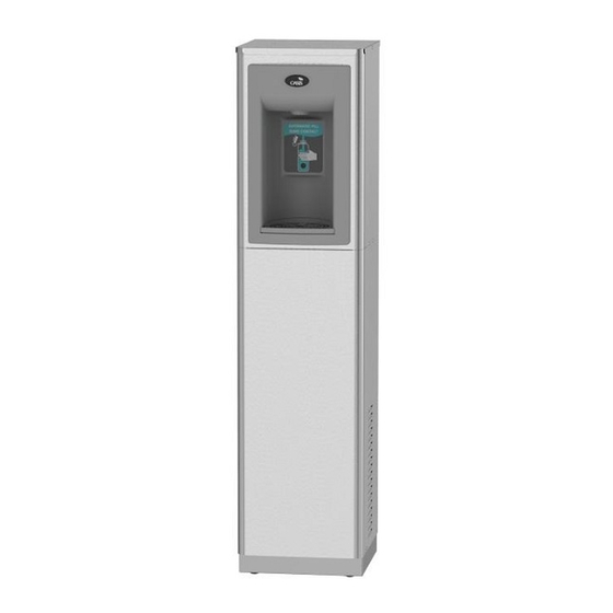
- Page 1 FREE STANDING CONTACTLESS BOTTLE FILLER Installation Instructions For: UNFILTERED PCPEBF PCP10EBF PCPEBFY (230V) PCP10EBFY (230V) FILTERED PFCP10EBF OASIS International 222 East Campus View Blvd. Columbus, OH 43235 614-861-1350 www.oasiscoolers.com...
-
Page 2: Product Specifications
INDEX INDEX INDEX INDEX PRODUCT SPECIFICATIONS IMPORTANT REQUIREMENTS SAFETY WARNINGS GETTING STARTED PROPER QUICK CONNECT FITTING CONNECTION INSTRUCTIONS INSTALLATION SET-UP GUIDE FOR DISPENSER PCB ELECTRONICS 1. PRODUCT SPECIFICATIONS 1. PRODUCT SPECIFICATIONS 1. PRODUCT SPECIFICATIONS 1. PRODUCT SPECIFICATIONS Dimensions: Depth 13.35”(339.0 mm) Width 12”... - Page 3 ROUGHING-IN AND DIMENSIONAL DRAWING...
-
Page 4: Important Requirements
2. IMPORTANT REQUIREMENTS 2. IMPORTANT REQUIREMENTS • Use only original and new parts to guarantee the reliability, optimization, and performance of the OASIS water machine. • Always wear proper protection when performing any type of service or maintenance. • When cleaning the unit, do not use corrosive acidic products, or metal brushes. -
Page 5: Getting Started
4. GETTING STARTED: 4. GETTING STARTED: 4. GETTING STARTED: 4. GETTING STARTED: What’s Included: CONTACTLESS BOTTLE FILLER STABILIZER BRACKET OPTIONAL VERSAFILTER III STABILIZER BRACKET VERSAFILTER III (Filtered models only) CONTACTLESS BOTTLE FILLER... - Page 6 5. PROPER QUICK CONNECT FITTING CONNECTION 5. PROPER QUICK CONNECT FITTING CONNECTION 5. PROPER QUICK CONNECT FITTING CONNECTION 5. PROPER QUICK CONNECT FITTING CONNECTION INSTRUCTIONS: INSTRUCTIONS: INSTRUCTIONS: INSTRUCTIONS: Quick-Connect Fittings • If you need to cut the plastic tubing, be sure to cut tube ends square and straight.
- Page 7 6. INSTALLATION: 6. INSTALLATION: 6. INSTALLATION: 6. INSTALLATION: STEP 1 & 2: Carefully unpack Water Dispenser and remove filter from the alcove (filtered models only). Remove Front Panel by removing the 2 screws at the bottom of the panel on the sides. See Diagram 1 and 2. DIAGRAM 1 DIAGRAM 2 REMOVE...
- Page 8 6. INSTALLATION: 6. INSTALLATION: 6. INSTALLATION: 6. INSTALLATION: STEPS 3 through 5 (for optional filters) Note: The VersaFilter III was placed in the alcove on the front of the cooler for shipping. Unpack the VersaFilter III and remove the sanitary cap. Looking at the filter top, orient the filter so that the rectangular lug, on top of the filter faces forward.
- Page 9 6. INSTALLATION: 6. INSTALLATION: 6. INSTALLATION: 6. INSTALLATION: STEP 6: Locate the Snap Bushing in the back of the cabinet and feed 1-1/2” OD Drain Pipe through the hole. See Diagram 4 & 5. Drain Pipe – shown after completing Step 6.
- Page 10 6. INSTALLATION: 6. INSTALLATION: 6. INSTALLATION: 6. INSTALLATION: STEPS 7 through 9: Connecting 1/4” OD water supply tube to 1/4” quick connect fitting on the back of the unit. Refer to Section 5 for instructions on how to properly connect to quick connect fittings. IMPORTANT: Before connecting water supply to dispenser, flush building water supply.
- Page 11 6. INSTALLATION: 6. INSTALLATION: 6. INSTALLATION: 6. INSTALLATION: STEPS 10 through 17: 10. ENERGIZING UNIT: Check the available power supply against the water dispenser data plate to assure correct electrical service. This water dispenser is intended to be connected to a 20A minimum ground fault circuit interrupting (GFCI) device to meet UL requirements.
- Page 12 Pushbutton To change the program settings, follow these steps: P/N 030099-626, 7/2020 ©2020 LVD Acquisition, LLC; OASIS is a registered trademark of LVD Acquisition, LLC dba OASIS International.
Need help?
Do you have a question about the PCPEBF and is the answer not in the manual?
Questions and answers