Table of Contents
Advertisement
Quick Links
USER GUIDE
NI USB-6001/6002/6003 OEM
This document provides information about the dimensions, pinouts, connectors, LEDs, and
mounting holes of the National Instruments USB-6001/6002/6003 OEM device.
For more information about the device, refer to the NI USB-6001/6002/6003 User Guide and
NI USB-6001 Specifications, NI USB-6002 Specifications, and NI USB-6003 Specifications
documents available at
Caution
CE marking compliance claims made for the NI USB-6001/6002/6003 OEM
devices.
The NI USB-6001/6002/6003 OEM device is intended to be used as a component of
a larger system. National Instruments can help developers meet their compliance
requirements. The end product supplier, however, is responsible for conforming to
any and all compliance requirements.
ni.com/manuals
There are no product safety, electromagnetic compatibility (EMC), or
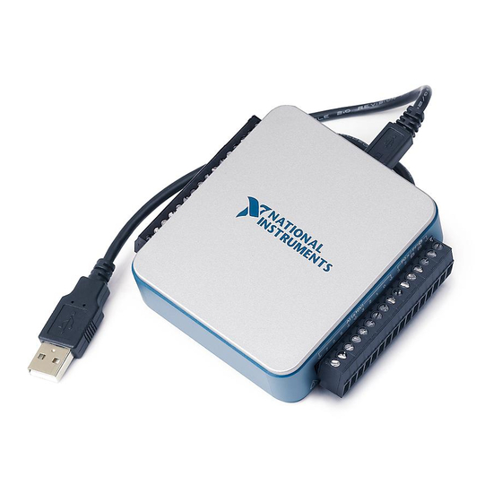
Figure 1. USB-6001/6002/6003 OEM Device
.
Advertisement
Table of Contents

Subscribe to Our Youtube Channel
Summary of Contents for National Instruments USB-6001
- Page 1 This document provides information about the dimensions, pinouts, connectors, LEDs, and mounting holes of the National Instruments USB-6001/6002/6003 OEM device. For more information about the device, refer to the NI USB-6001/6002/6003 User Guide and NI USB-6001 Specifications, NI USB-6002 Specifications, and NI USB-6003 Specifications documents available at ni.com/manuals...
-
Page 2: Specifications
USB-6001/6002/6003 OEM Device Specifications Most specifications of the USB-6001/6002/6003 OEM device are listed in the NI USB-6001, NI USB-6002, NI USB-6003 Specifications documents on . The following ni.com/manuals sections contain exceptions to the main specifications. Physical Characteristics Weight ...............31 g (1.10 oz) Dimensions ............98 mm ×... -
Page 3: I/O Connector Pinouts
AI 3 (AI 3+) AI GND AO GND Signal Descriptions Most of the signals available on the I/O connector are described in the NI USB-6001/6002/6003 User Guide document available for download at . Table 1 describes ni.com/manuals additional signals on the I/O connector of the OEM device. - Page 4 Using the 34-Pin Connector with a Board Mount Socket The USB-6001/6002/6003 OEM device can be mounted to a motherboard using the 34-pin connector, as shown in Figures 4 and 5. Figure 4. Mounting Using a 34-Pin Connector Board Mount Socket...
-
Page 5: Connecting To Usb
Figure 5. USB Device Installed on Motherboard Connecting to USB You can use the USB connector on the USB-6001/6002/6003 OEM device to connect to the USB host. In this case, leave the D+ and D- signals and VBUS (on the 34-pin connector) unconnected. - Page 6 Typical Maximum = 8 mA — 0.4 V Output Low Voltage = 18 mA 1.2 V — External Pull-up Voltage — — 5.25 V Maximum Sinking Current — — 18 mA 6 | ni.com | NI USB-6001/6002/6003 OEM User Guide...
-
Page 7: Device Components
Standoff Using — — — 4.76 mm (3/16 in.) ribbon HEX female-to- cable female, 6.35 mm (1/4 in.) long Screw — — — M3 × 0.5, 4-40 UNC NI USB-6001/6002/6003 OEM User Guide | © National Instruments | 7... -
Page 8: Worldwide Support And Services
NI product. Refer to the Export Compliance Information at ni.com/legal/export-compliance for the National Instruments global trade compliance policy and how to obtain relevant HTS codes, ECCNs, and other import/export data. NI MAKES NO EXPRESS OR IMPLIED WARRANTIES AS TO THE ACCURACY OF THE INFORMATION CONTAINED HEREIN AND SHALL NOT BE LIABLE FOR ANY ERRORS.


Need help?
Do you have a question about the USB-6001 and is the answer not in the manual?
Questions and answers