
Related Manuals for Icom MA-500TR


Summary of Contents for Icom MA-500TR
- Page 1 INSTRUCTION MANUAL CLASS B AIS TRANSPONDER MA-500TR This device complies with Part 15 of the FCC Rules. Operation is subject to the condition that this device does not cause harmful interference.
-
Page 2: Explicit Definitions
Thank you for choosing this Icom product. This product is de- EXPLICIT DEFINITIONS signed and built with Icom’s state of the art technology and craftsmanship. With proper care this product should provide WORD DEFINITION you with years of trouble-free operation. -
Page 3: Supplied Accessories
SUPPLIED ACCESSORIES MXG-5000S is sold as a set with the MA-500TR. gps receiver NMEA connector cable DC power cable (OPC-2059) (OPC-2014) • The OPC-2014 has 15 leads, numbered 1 to 15. MXG-5000S Mounting bracket MXG-5000S (Referred to as Internal GPS) Cable length: Approx. -
Page 4: Radio Operator Warning
RADIO OPERATOR WARNING Icom requires the radio operator to meet the FAILURE TO OBSERVE THESE LIMITS MAY ALLOW FCC Requirements for Radio Frequency Expo- THOSE WITHIN THE MPE RADIUS TO EXPERIENCE RF sure. An omnidirectional antenna with gain not RADIATION ABSORPTION WHICH EXCEEDS THE FCC greater than 9 dBi must be mounted a minimum MAXIMUM PERMISSIBLE EXPOSURE (MPE) LIMIT. -
Page 5: Installation Note
The exposure to RF electromagnetic field is only applicable when this device is transmitting. This exposure is naturally re- Icom, Icom Inc. and Icom logo are registered trademarks of Icom Incorporated duced due to the nature of alternating periods of receiving and (Japan) in Japan, the United States, the United Kingdom, Germany, France, transmitting. -
Page 6: About Ce And Doc
ABOUT CE AND DOC COUNTRY CODE LIST • ISO 3166-1 Hereby, Icom Inc. declares that the versions of MA-500TR which have the “CE” symbol on the Country Codes Country Codes product, comply with the essential requirements Austria Liechtenstein of the Radio Equipment Directive, 2014/53/EU,... -
Page 7: Precautions
CAUTION: Changes or modifications to this device, not operation of the vessel may be hindered or where it could expressly approved by Icom Inc., could void your authority to cause bodily injury. operate this device under FCC regulations. KEEP the transponder at least 1 m (3.3 ft) away from the... -
Page 8: Table Of Contents
TABLE OF CONTENTS 5 OTHER FUNCTIONS ..........25–29 IMPORTANT ................. i EXPLICIT DEFINITIONS ............i ■ Message ..............25 SUPPLIED ACCESSORIES ..........ii ■ Waypoint ..............26 RADIO OPERATOR WARNING .......... iii ■ Lost target ..............29 INSTALLATION NOTE ............iv 6 MENU MODE OPERATION ........30–36 FCC INFORMATION ............ -
Page 9: Overview
OVERVIEW D ABOUT AIS D AIS Classes AIS is an acronym for “Automatic Identification System.” There are seven types of AIS stations; vessels, base stations, An AIS transponder is a short range data radio unit, used Aids to Navigation (AtoN), Search and Rescue (SAR), Search primarily for collision-risk management and navigation safety. -
Page 10: Panel Description
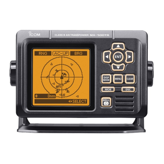
PANEL DESCRIPTION ■ Front panel q DISPLAY MODE KEY [DISP MODE] Function display (p. 4) <Common> ➥ Push to switch the display mode between the plotter, target list and danger list. (pp. 4−6) ➥ While in the Menu mode, push to exit it, and return to the plotter, target list or danger list display which was selected before you entered the Menu mode. -
Page 11: Individual Dsc Call (Possible Only When A Transceiver Is Connected)
PANEL DESCRIPTION e UP AND DOWN KEYS [∫]/[√] y CLEAR KEY [CLEAR] <Common> <Common> ➥ While in the Menu mode, push to select a menu item. ➥ Push to cancel the entered function, or return to the pre- (pp. 9, 30) vious screen. - Page 12 A6860D-1EX-8 Printed in Japan 2011–2018 Icom Inc. © 1-1-32 Kamiminami, Hirano-ku, Osaka 547-0003, Japan Printed on recycled paper with soy ink.
Need help?
Do you have a question about the MA-500TR and is the answer not in the manual?
Questions and answers