Table of Contents
Advertisement
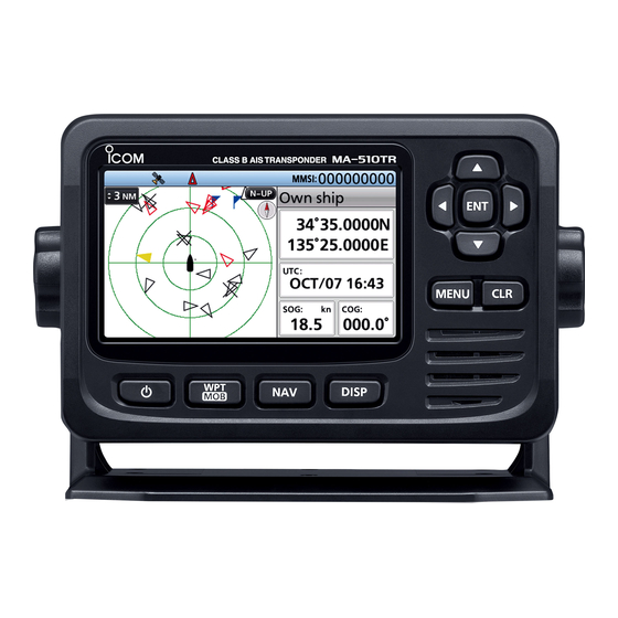
INSTRUCTION MANUAL
CLASS B AIS TRANSPONDER
MA-510TR
This device complies with Part 15 of the FCC
rules. Operation is subject to the following two
conditions: (1) This device may not cause harmful
interference, and (2) this device must accept any
interference received, including interference that
may cause undesired operation.
Advertisement
Table of Contents

Related Manuals for Icom MA-510TR


Summary of Contents for Icom MA-510TR
- Page 1 INSTRUCTION MANUAL CLASS B AIS TRANSPONDER MA-510TR This device complies with Part 15 of the FCC rules. Operation is subject to the following two conditions: (1) This device may not cause harmful interference, and (2) this device must accept any interference received, including interference that may cause undesired operation.
-
Page 2: Important
Thank you for choosing this Icom product. This product was designed and built with Icom’s state of the art technology and craftsmanship. With proper care, this product should provide you with years of trouble- free operation. ■ Important ■ Explicit definitions... -
Page 3: Recommendation
It is recommended that antenna of a maximum gain of 3 dB is used. If higher gain antenna is required then please contact your Icom distributor for revised installation recommendations. -
Page 4: Radio Operation Warning
■ Radio operation warning Icom requires the radio operator to meet the FCC Requirements for Radio Frequency Exposure. An omnidirectional antenna with gain not greater than 9 dBi must be mounted a minimum of 5 meters (measured from the lowest point of the antenna) vertically above the main deck and all possible personnel. -
Page 5: Avertissement Pour Les Opérateurs Radio
■ Avertissement pour les opérateurs radio Icom exige que l’opérateur radio se conforme aux exigences de la FCC en matière d’exposition aux radiofréquences. Une antenne omnidirectionnelle dont le gain ne dépasse pas 9dBi doit être fixée à une distance minimale de 5 mètres (mesurée depuis le point le plus bas de l’antenne) verticalement au-dessus du pont principal et de tout... -
Page 6: Precautions
■ Precautions R WARNING! NEVER connect the BE CAREFUL! The transponder’s rear transponder directly to an AC outlet. This panel will become hot when transmitting may cause a fire or an electric shock. continuously for long periods of time. R WARNING! NEVER connect the BE CAREFUL! The transponder meets transponder to a power source of more IPX7 requirements for waterproof... -
Page 7: Précautions
■ Précautions R AVERTISSEMENT ! NE JAMAIS relier MISE EN GARDE : La face arrière de le le transpondeur à une prise CA. Cela transpondeur chauffe en cas d’utilisation pourrait provoquer un choc électrique ou un continue sur une longue durée. incendie. -
Page 8: Fcc Information
CAUTION: Changes or modifications to this transponder, not expressly approved by Icom Inc., could void your authority to operate this transponder under FCC regulations. ■ Information FCC Cet équipement a été... -
Page 9: Table Of Contents
■ Table of contents ■ Important ......... i CONNECTIONS AND INSTALLATION ............38 ■ Features .......... i ■ Supplied accessories ....38 ■ Explicit definitions......i ■ Définitions explicites......i ■ GPS antenna connection ..... 39 ■ Recommendation ......ii ■ Connections ......... 40 ■... -
Page 10: Overview
OVERVIEW ■ About AIS The Automatic Identification System (AIS) is primarily used for collision-risk management and navigation safety. It may automatically transmit and receive vessel information, such as the vessel name, MMSI code, vessel type, position data, speed, course, destination, and more, depending on the class. -
Page 11: Panel Description
PANEL DESCRIPTION ■ Front panel Function display (p. 3) Speaker 1 ENTER KEY [ENT] 6 DISPLAY KEY [DISP] (p. 11) Push to set the entered data, selected Push to switch the main screen item, and so on. between the AIS (Plotter), AIS and Steering, AIS and Highway, and 2 LEFT/RIGHT KEYS [◄]/[►] Highway screens. -
Page 12: Function Display
PANEL DESCRIPTION ■ Function display 1 2 3 4 5 6 Main screen (p. 11) 1 TX OFF INDICATOR 2 GPS ICON Displayed when the TX function is OFF. • Displayed when GPS data is received. (p. 21) • Blinks while searching GPS data. (p. -
Page 13: Preparation
PREPARATION ■ Entering the MMSI code The Maritime Mobile Service Identity (MMSI: DSC self ID) code consists of 9 digits. This initial code can be entered only once. After entering, it can be changed only by your dealer or distributor. If your MMSI code has already been entered, doing the steps below is not necessary. -
Page 14: Entering Own Ship Data
PREPARATION ■ Entering Own ship data Your vessel’s information is exchanged among vessels and/or base stations. NOTE: After entering the MMSI code, the transponder automatically enters the “OWN SHIP DATA” screen. In this case, skip steps 1 ~ 3. Push [MENU]. •... - Page 15 PREPARATION D Own ship data items MMSI Type of ship Enter the vessel’s MMSI code. Select your vessel type. L See page 4 for details. L The selectable ship types may differ, L If the MMSI code has already been set, depending on the presetting.
-
Page 16: Menu Screen
MENU SCREEN The Menu screen is used to set items, select options, and so on for the transponder’s functions. See page 33 for the Menu items description. ■ Menu construction The Menu screen is constructed in a tree To select an item, push [▲] or [▼]. structure. -
Page 17: Selecting A Menu Item
MENU SCREEN ■ Selecting a Menu item Follow the procedures described below to select a Menu item. Example: Setting the key beep to “OFF.” Push [MENU]. • The Menu screen is displayed. Push [▲] or [▼] to select “Configuration,” and then push [ENT]. -
Page 18: Basic Operation
BASIC OPERATION ■ Turning ON the transponder IMPORTANT: BE SURE to connect a GPS antenna or receiver and a marine VHF antenna to the transponder before turning ON the transponder. (p. 40) Hold down [ ] for 1 second to turn ON the transponder. •... -
Page 19: Backlight Function
BASIC OPERATION ■ Backlight function The Function display and keys can be backlit for better visibility under low light conditions. And, you can set the Backlight mode to Day mode or Night mode. The Day mode is for the daytime operation, and the screen items are in full color. The Night mode is for the nighttime operation, and the screen items are in black and red. -
Page 20: Using The Main Screen
BASIC OPERATION ■ Using the Main screen There are 4 types of Main screens, AIS, AIS and Steering, AIS and Highway, and Highway screen (only for watching). In the AIS screen, the display range, the icons of the AIS target or waypoint, and GPS data are displayed. - Page 21 BASIC OPERATION D AIS screen Displays the plotter display and selected 5 INFORMATION BOX target’s information. Displays the selected target’s information. L The contents may differ, depending on the selected target. (p. 15) 6 PLOTTER DISPLAY Displays the display range and the icons of the AIS target or waypoint.
- Page 22 BASIC OPERATION D AIS and Steering screen D AIS screen 8 VESSEL TRACK Displays the plotter display and steering Displays your vessel track. information. 9 ANCHOR WATCH • Displays (a red circle) as the start position of anchor watch. • Displays a red dashed circle as the range of anchor watch.
- Page 23 BASIC OPERATION D AIS and Highway screen D Highway screen Displays the plotter display and highway Displays the highway information. information. 1 HIGHWAY Displayed during navigation. 1 OWN SHIP INDICATOR L “Navigation OFF” is displayed on the Displayed in the center of the compass. Highway screen when the Navigation 2 WAYPOINT NAME mode is not used.
- Page 24 BASIC OPERATION D About the information box The information box displays the information about the selected AIS target or waypoint. The contents may differ, depending on the selected target. z Push [◄] or [►] to select an AIS target or waypoint on the AIS screen.
-
Page 25: Using The Ais List Screen
BASIC OPERATION ■ Using the AIS list screen There are 3 types of AIS lists, Target, Danger, and Friends. The target’s information is automatically updated every 5 seconds, and then the AIS target data is sorted. Push [MENU]. • The Menu screen is displayed. Push [▲] or [▼] to select “AIS list,”... - Page 26 BASIC OPERATION D Target/Friends list screen D Danger list screen The Target list screen displays all AIS The Danger list screen displays any targets that the transponder detects. Danger target whose CPA (Closest Point of Approach) distance and TCPA (Time to The Friends list screen displays the AIS CPA) time are less than the set values.
-
Page 27: Setting A Friend
BASIC OPERATION ■ Setting a Friend You can set up to 100 AIS targets as a Friend in the Friends list. An alarm sounds when a Friend is detected, depending on the setting. (p. 34) D Entering an ID There are 3 ways of setting a Friend, using the Friends list, selecting in the AIS list, or selecting on the plotter display. -
Page 28: About The Detail Screen
BASIC OPERATION ■ About the detail screen The detail screen displays the information about the selected AIS target or waypoint. The contents may differ, depending on the selected target. L When a Danger target is selected, is displayed. (p. 17) L When a Friend target is selected, is displayed. - Page 29 This MA-510TR displays a three part AIS class vendor ID separated by a slash (/). MMSI code The first part is fixed at “ICO” (ICOM). Target name The second part is the generation CPA (Closest Point of Approach) number for the AIS transponder under TCPA (Time to CPA) Icom products.
-
Page 30: Ais Settings
BASIC OPERATION ■ AIS settings AIS settings can be customized in “AIS settings” on the Menu screen. CPA/TCPA Turn the TX function ON or OFF. z Alarm You can select whether or not to turn WARNING: If this setting is “OFF,” AIS the following alarm functions ON or data is not transmitted. - Page 31 BASIC OPERATION ■ AIS settings CPA/TCPA CPA/TCPA z Slow warn z ID blocking The GPS receiver calculated COG data Enter an MMSI (Maritime Mobile of a vessel that is at anchor or drifting Service Identity) code not to sound a is unreliable, and therefore the CPA collision alarm.
-
Page 32: Other Functions
OTHER FUNCTIONS ■ Message D Receiving a message A safety-related message of up to 161 characters can be received from an AIS equipped vessel in the area. When a message is received, a beep sounds, and a popup screen is displayed. •... -
Page 33: Waypoint
OTHER FUNCTIONS ■ Waypoint D Waypoint list The transponder saves up to 100 waypoints in the waypoint list. Open the “Waypoint” screen. [MENU] > Navigation settings > Waypoint Push [▲] or [▼] to select a waypoint. L Push [◄] to sort the waypoint data by Name. L Push [►] to sort the waypoint data by Range. - Page 34 OTHER FUNCTIONS D Entering a waypoint The position information that you want to memorize can be added as a waypoint. NOTE: You can also add your current position as a waypoint by pushing [WPT/MOB]. Open the “Waypoint” screen. [MENU] > Navigation settings > Waypoint Push [ENT] to display the Menu window.
- Page 35 OTHER FUNCTIONS D Editing a waypoint A waypoint’s name, latitude, longitude data can be edited. Open the “Waypoint” screen. [MENU] > Navigation settings > Waypoint Push [▲] or [▼] to select a waypoint. L Push [◄] to sort the waypoint data by Name. L Push [►] to sort the waypoint data by Range.
-
Page 36: Mob (Man Overboard)
OTHER FUNCTIONS ■ MOB (Man Overboard) The transponder assists you in rescuing a man who has fallen overboard. L The function works only when the transponder is receiving valid GPS signals. L The transponder automatically exits the Navigation mode if it is in that mode. D Starting MOB z Hold down [WPT/MOB] for 1 second to start the MOB mode. -
Page 37: Navigation
L The function works only when the transponder is receiving valid GPS signals. L The function cannot work while in the MOB mode. NOTE: MA-510TR’s Navigation function is a supplemental aid to navigation only, and is not intended to be a substitute for primary Navigation equipment. - Page 38 OTHER FUNCTIONS Selecting on the plotter display: Push [◄] or [►] to select an AIS target or waypoint. • A target box is displayed around the selected target. (p. 13) Push [ENT] to display the Menu window. • The Menu window is displayed. Select “Navigate to,”...
-
Page 39: Lost Target
OTHER FUNCTIONS ■ Lost target A vessel is regarded as a “Lost target” after a specified period of time has passed since the vessel last transmitted data, as described below. The “Lost target” icon disappears from the plotter display 6 minutes and 40 seconds after the vessel was regarded as a “Lost target.”... -
Page 40: Individual Dsc Call
OTHER FUNCTIONS ■ Individual DSC call (Possible only when a transceiver is connected.) When a transceiver is connected to the transponder, you can transmit an Individual DSC call without entering the vessel’s MMSI code, by simply selecting its AIS target and the voice channel on the transponder. -
Page 41: Menu Items
MENU ITEMS ■ Menu items The Menu screen is constructed in a tree structure. (p. 7) See the referred pages for each item. L The displayed menu items may differ, depending on the presetting. AIS list Friends Target list Friends list p. -
Page 42: Menu Items Description
MENU ITEMS ■ Menu items description D Navigation settings Waypoint Anchor watch z Function Displays the Waypoint list. L See page 24 for details. You can select whether or not to sound an alarm when your vessel is at anchor, Reset navigation and has drifted. - Page 43 MENU ITEMS D Friends Friends list NMEA 2000 Displays all Friend targets that you have NMEA 2000 is a communication standard entered. used to connect various marine devices L “No ID” is displayed when there is no and display units in the vessel. Friend target.
- Page 44 MENU ITEMS Compatible PGN list Receive 059392 ISO Acknowledgment 126208 NMEA 059904 ISO Request 126996 Product Information COG (Course Over Ground) and ISO Transport Protocol, Data 060160 129026 SOG (Speed Over Ground) - Transfer Rapid Update ISO Transport Protocol, GNSS (Global Navigation 060416 129029 Connection Management...
- Page 45 MENU ITEMS D Configuration Backlight Unit You can set the Backlight mode to Day You can select the unit to display a mode or Night mode. distance and speed. L See page 10 for details. NM, kn: “NM, kn” is used. km, km/h: “km, km/h”...
- Page 46 MENU ITEMS D Radio information Status log Displays the type, date, and time of the last Displays your transponder’s Serial number, 25 malfunctions that were detected. Software version, AIS engine version, and GPS engine version. Alarm type Date Time Description of the alarm type Alarm type Description Displayed when “GPS...
-
Page 47: Connections And Installation
CONNECTIONS AND INSTALLATION ■ Supplied accessories DC power cable Mounting bracket For the mounting bracket Knob bolts Flat washers (M5) Screws (5 × 20 mm) Spring washers (M5) Accessory GPS antenna For the GPS antenna connector Mounting bracket Cable length (approximate): 10 m, 32.8 ft D Accessory connector set up... -
Page 48: Gps Antenna Connection
CONNECTIONS AND INSTALLATION ■ GPS antenna connection NOTE: Be sure the GPS antenna is positioned where the GPS antenna has a clear view to receive signals from satellites. D Installation Mount the bracket securely to the desired position. L Screws for mounting the bracket are user supplied. Insert the GPS antenna to the bracket, and then rotate it clockwise until it is completely tightened. -
Page 49: Connections
CONNECTIONS AND INSTALLATION ■ Connections 1 VHF ANTENNA CONNECTOR Connects to a marine VHF antenna with a PL-259 connector. A key element in the performance of any communication system is the antenna. Ask your dealer about antennas and the best place to mount them. CAUTION: DO NOT transmit without an antenna. - Page 50 CONNECTIONS AND INSTALLATION D Connector information NMEA 0183 Sentence Pin name Specification Description format 1 GND – – Connects to ground. Connects to the NMEA input/ 2 NMEA IN (–) Input level: output connector of a transceiver to Less than 2 mA –...
-
Page 51: Connecting To The Transceiver
CONNECTIONS AND INSTALLATION NOTE: • When an external GPS receiver is not connected, RMC, GSA, and GSV sentences are only output from the internal receiver. • When the NMEA sentences are input from an external GPS receiver, all the sentences*, as described to the left, are passed to the output terminal. *The external GPS receiver requires the GBS sentence output. -
Page 52: Mounting The Transponder
CONNECTIONS AND INSTALLATION ■ Mounting the transponder D Using the supplied mounting bracket You can mount the transponder on a dashboard using the universal mounting bracket supplied with your transponder. CAUTION: KEEP the transponder at least 1 meter (3.3 ft) away from the vessel’s magnetic navigation compass. -
Page 53: Installation
CONNECTIONS AND INSTALLATION ■ MB-132 installation An optional MB-132 flush mount kit is used to mount the transponder to a flat surface such as an instrument panel. CAUTION: Keep the transponder at least 1 meter (3.3 feet) away from your vessel’s magnetic navigation compass. -
Page 54: Specifications And Options
SPECIFICATIONS AND OPTIONS ■ Specifications L All stated specifications are subject to change without notice or obligation. General 161.500 ~ 162.025 MHz Frequency coverage 156.525 MHz 16K0GXW (GMSK) Type of emission 16K0G2B Antenna impedance 50 Ω nominal CH-A 1st: 21.700 MHz, 2nd: 450 kHz Intermediate frequency CH-B 1st: 30.150 MHz, 2nd: 450 kHz... -
Page 55: Options
Cable length (approximate) 10 m, 32.8 ft D Dimensions Unit: mm (inch) MA-510TR 145 (5.7) 166.2 (6.5) 26.2 66.3 (2.3) MA-510TR with the mount bracket GPS antenna 26.2 186 (7.3) 96.2 (3.8) 66.3 (2.3) 145 (5.7) unit: mm (inch) 164 (6.5) 66.2... -
Page 56: Maintenance
MAINTENANCE ■ Troubleshooting The transponder does not turn ON. z Bad connection to the power supply. → Check the connection to the transponder and power supply. (p. 40) z The fuse is blown. → Repair the problem, and then replace the fuse. (p. 42) You cannot transmit. -
Page 57: Error Messages
MAINTENANCE ■ Error messages An error message is displayed when a malfunction occurs that has an error message programmed for it. Message contents Description GPS malfunction No Displayed when no GPS data is received for 60 seconds. GPS data RX malfunction No Displayed when the transponder receive circuit has failed. -
Page 58: Aton Code Description
AtoN CODE DESCRIPTION The following table lists all the AtoN codes that are displayed on the detail screens of an “AtoN” or “AtoN virtual.” (p. 20) Type of AtoN Code Description Default, Type of AtoN not specified Reference point RACON Fixed structures off-shore, such as oil platforms, wind farms. -
Page 59: Template
TEMPLATE 93�3 (3 ⁄ 110�2 (4 ⁄ Unit: mm (inch) -
Page 61: Index
INDEX Language Options ������������������������ 46 About AIS ������������������ 1 Configuration ����������� 36 Own ship data AIS classes ��������������� 1 Lost target�������������������� 30 Entering ��������������������� 5 AIS list Items ������������������������� 6 Danger list ��������������� 17 Main screen Friends list ��������������� 17 AIS ��������������������������... - Page 62 MEMO...
- Page 63 MEMO...
- Page 64 A7549D-1EX 1-1-32 Kamiminami, Hirano-ku, Printed in Japan Osaka 547-0003, Japan © 2019 Icom Inc� Nov� 2019...
Need help?
Do you have a question about the MA-510TR and is the answer not in the manual?
Questions and answers