Siemens 7SR45 Manual
Reyrolle
Hide thumbs
Also See for 7SR45:
- User manual (120 pages) ,
- Device manual (118 pages) ,
- Quick reference (2 pages)
Table of Contents
Advertisement
Quick Links
Reyrolle
Operating
7SR45
V03.00
Manual
C53000-B7040-C101-1
Preface
Open Source Software
Table of Contents
First Steps
Installing the Device
Handling of the Device
Using the Relay Fascia
Using Reydisp Evolution
In Service Operation
Commissioning
Device Maintenance
Security Settings
Appendix
Index
1
2
3
4
5
6
7
8
9
A
Advertisement
Table of Contents

Related Manuals for Siemens 7SR45


Summary of Contents for Siemens 7SR45
- Page 1 Preface Open Source Software Table of Contents Reyrolle First Steps Operating Installing the Device 7SR45 Handling of the Device Using the Relay Fascia V03.00 Using Reydisp Evolution Manual In Service Operation Commissioning Device Maintenance Security Settings Appendix Index C53000-B7040-C101-1...
- Page 2 Disclaimer of Liability Copyright Subject to changes and errors. The information given in Copyright © Siemens 2020. All rights reserved. this document only contains general descriptions and/or The disclosure, duplication, distribution and editing of this performance features which may not always specifically...
-
Page 3: Preface
Further Documentation [dw_7SR45_furtherdocumentation_operatingmanual, 1, en_US] • Device manual The device manual describes the functions and applications of the Reyrolle 7SR45 device. The printed manual for the device has the same informational structure. • Hardware manual The hardware manual describes the hardware building blocks and device combinations of the Reyrolle 7SR45 device family. - Page 4 The engineering guide describes the essential steps when engineering with Reydisp Evolution. In addi- tion, the engineering guide shows you how to load a planned configuration to a Reyrolle 7SR45 device and update the functionality of the Reyrolle 7SR45 device.
- Page 5 Preface WARNING WARNING means that death or severe injury may result if the measures specified are not taken. Comply with all instructions, in order to avoid death or severe injuries. ² CAUTION CAUTION means that medium-severe or slight injuries can occur if the specified measures are not taken. Comply with all instructions, in order to avoid moderate or minor injuries.
- Page 6 Reyrolle, Operating, Manual C53000-B7040-C101-1, Edition 08.2020...
-
Page 7: Open Source Software
License Conditions provide for it you can order the source code of the Open Source Software from your Siemens sales contact – against payment of the shipping and handling charges – for a period of at least 3 years after purchase of the product. We are liable for the product including the Open Source Software contained in it pursuant to the license conditions applicable to the product. - Page 8 Reyrolle, Operating, Manual C53000-B7040-C101-1, Edition 08.2020...
-
Page 9: Table Of Contents
Table of Contents Preface................................3 Open Source Software..........................7 First Steps..............................13 Unpacking, Repacking, Returning, Transporting, and Storing..........14 Incoming Inspection ......................16 Electrical Inspection ......................17 Installing the Device........................... 19 Drilling Patterns and Device Dimensions................20 Mounting Instructions.......................23 Installing Devices......................24 Earthing and Connecting Devices .................. - Page 10 Table of Contents 4.6.4 Parameter Edit Screen ....................57 Using Reydisp Evolution..........................59 General..........................60 Connecting to the Relay for Setting via Reydisp Evolution..........62 In Service Operation........................... 63 Overview.......................... 64 Safety Notes........................65 Operation Options......................66 6.3.1 General........................66 Modes of Operation......................67 6.4.1 Overview........................67 6.4.2...
- Page 11 Table of Contents Self Monitoring ........................ 91 General Information......................93 Troubleshooting....................... 94 Replace and Return Defective Device................. 95 8.5.1 Backup Device ......................95 8.5.2 Replacing a Device ...................... 95 8.5.3 Returning a Device ......................95 Firmware Update ......................96 Security Settings............................97 Confirmation ID (Password Feature).................. 98 Appendix..............................
- Page 12 Reyrolle, Operating, Manual C53000-B7040-C101-1, Edition 08.2020...
-
Page 13: First Steps
First Steps Unpacking, Repacking, Returning, Transporting, and Storing Incoming Inspection Electrical Inspection Reyrolle, Operating, Manual C53000-B7040-C101-1, Edition 08.2020... -
Page 14: Unpacking, Repacking, Returning, Transporting, And Storing
Devices are packed on site in a way that meets the requirements of standard ISO 2248. Returning a Device In order to return the device to the Siemens factory or any Siemens location, contact the customer ² support center and follow the instructions specified by them. - Page 15 Warning about battery disposal. Noncompliance with the safety instructions can result in severe injuries or considerable material damage. Batteries can only be replaced by the ones recommended by Siemens. Replacing with the wrong type ² of batteries can cause an explosion hazard.
-
Page 16: Incoming Inspection
First Steps 1.2 Incoming Inspection Incoming Inspection Safety Notes DANGER Danger during incoming inspection Noncompliance with the safety notes, can result in death, severe injury or considerable material damage. Comply with all given safety notes when carrying out the incoming inspection. ²... -
Page 17: Electrical Inspection
The battery compartment is located on the front of the device. You do not have to take the battery out of the compartment in order to remove the paper strip. Earthing a Device The 7SR45 devices are protection class III equipment. The devices must be connected with the system earth prior to commissioning. ²... - Page 18 First Steps 1.3 Electrical Inspection Safety Notes DANGER Danger during electrical inspection Noncompliance with the safety notes will result in death, severe injury or considerable material damage. Comply with all given safety notes when carrying out the electrical inspection. ² Note that hazardous voltages are present when you perform the electrical inspection.
-
Page 19: Installing The Device
Installing the Device Drilling Patterns and Device Dimensions Mounting Instructions Installing Devices Earthing and Connecting Devices Terminal Lugs Specification Environmental Protection Hints Reyrolle, Operating, Manual C53000-B7040-C101-1, Edition 08.2020... -
Page 20: Drilling Patterns And Device Dimensions
Installing the Device 2.1 Drilling Patterns and Device Dimensions Drilling Patterns and Device Dimensions [dw_7SR45 case dimensions panel cut out view, 1, en_US] Figure 2-1 Drilling Pattern Reyrolle, Operating, Manual C53000-B7040-C101-1, Edition 08.2020... - Page 21 Installing the Device 2.1 Drilling Patterns and Device Dimensions [dw_7SR45 case dimensions front view, 4, en_US] Figure 2-2 Front View [dw_7SR45 case dimensions front view with cover, 2, en_US] Figure 2-3 Front view with cover Reyrolle, Operating, Manual C53000-B7040-C101-1, Edition 08.2020...
- Page 22 Installing the Device 2.1 Drilling Patterns and Device Dimensions [dw_7SR45 case dimensions side view, 4, en_US] Figure 2-4 Side View [dw_7SR45 case dimensions side view with front cover, 2, en_US] Figure 2-5 Side View with Front Cover Reyrolle, Operating, Manual C53000-B7040-C101-1, Edition 08.2020...
-
Page 23: Mounting Instructions
Fasten the relay to the RMU/protection panel using 4 M4x20 Pan Phillips SS screws and nuts provided in ² the 7SR45 packing box with a torque of 0.5 Nm to 0.6 Nm. Carry-out all other installation steps and wiring connections from the protection panel. -
Page 24: Installing Devices
Installing the Device 2.3 Installing Devices Installing Devices Preparations NOTE The installation depth for 1 device is at least 235 mm. The M4 holes are the holes for the fastening screws of the device. NOTE Use a combidrive screwdriver. For each device, you need 4 M4x20 Pan Phillips SS screws with nut. DANGER Danger due to device being improperly screw-fastened Incomplete and careless screw fitting results in death, severe injury, or considerable material... -
Page 25: Earthing And Connecting Devices
Installing the Device 2.4 Earthing and Connecting Devices Earthing and Connecting Devices Earthing the Devices DANGER Danger due to device being improperly earthed Incomplete and careless earthing leads to death, severe injury, and considerable material damage! The device must be situated in the operating area for at least 2 hours before you connect it to the ²... -
Page 26: Terminal Lugs Specification
Installing the Device 2.5 Terminal Lugs Specification Terminal Lugs Specification Table 2-1 Terminal Lugs Specifications Terminal Blocks Cable Type/Cable Specifications Manufacturer/Part Number Torque Required Current inputs TE connectivity PIDG series insulated tin TE Connectivity Mfr. Part No. 1.0 Nm plated crimp ring terminal, M3.5 stud 2-327960-1 or equivalent size, 2.6 mm to 6.6 mm... -
Page 27: Environmental Protection Hints
When disposing of or transferring a mobile storage device, Siemens strongly recommends physically destroying it or completely deleting data from the mobile storage device by using a commercially available computer data erasing software. - Page 28 Reyrolle, Operating, Manual C53000-B7040-C101-1, Edition 08.2020...
-
Page 29: Handling Of The Device
Handling of the Device Battery Replacement Installing Transparent Front Cover Installing Surface Mounting Bracket Post Installation and Commissioning Replacement of the Device Reyrolle, Operating, Manual C53000-B7040-C101-1, Edition 08.2020... -
Page 30: Battery Replacement
Handling of the Device 3.1 Battery Replacement Battery Replacement You can replace the 7SR45 Argus Relay battery when it is damaged or exhausted. To replace the battery, follow the procedure: CAUTION Caution while replacing the battery. Risk of fire if the battery is replaced with incorrect type or polarity. - Page 31 Handling of the Device 3.1 Battery Replacement [dw_7SR45_batteryreplacement_step2, 1, en_US] Figure 3-2 Removing the Battery Insert the new battery in the battery clip with the correct polarity as indicated. ² [dw_7SR45_batteryreplacement_step3, 1, en_US] Figure 3-3 Inserting the New Battery Reyrolle, Operating, Manual C53000-B7040-C101-1, Edition 08.2020...
- Page 32 USB connection, test the relay by pressing the BAT ON/OFF key to confirm the relay functionality. NOTE Siemens recommends keeping the spare battery on a non-conductive surface to avoid any terminal short- ages. Reyrolle, Operating, Manual C53000-B7040-C101-1, Edition 08.2020...
-
Page 33: Installing Transparent
Fastener Kit 2 Specification for Transparent Front Cover Fastener Kit 2 Specifications Quantity M4 Knurled Screw Remove the 4 M4x20 Pan Philips stainless-steel screws and the 4 nuts from the 7SR45 Argus Relay and ² the protection panel/cubicle. Reyrolle, Operating, Manual... - Page 34 [dw_7SR45_transparentcover_step1, 1, en_US] Figure 3-5 Removing Screws from Protection Panel/Cubicle Fix the 7SR45 Argus Relay to protection panel/cubicle using 4 M4x20 Round SS studs, 4 lock washers and ² 4 nuts with a torque of 1.0 Nm. Reyrolle, Operating, Manual...
- Page 35 Handling of the Device 3.2 Installing Transparent Front Cover [dw_7SR45_transparentcover_step2, 1, en_US] Figure 3-6 Fixing Relay to Protection Panel/Cubicle Install the transparent front cover to the relay using 4 M4 knurled screws with a torque of 0.8 Nm. ² NOTE Ensure that the gasket is in place before fixing the M4 knurled screws.
- Page 36 Handling of the Device 3.2 Installing Transparent Front Cover [dw_7SR45_transparentcover_step3, 1, en_US] Figure 3-7 Install Transparent Front Cover to Relay Reyrolle, Operating, Manual C53000-B7040-C101-1, Edition 08.2020...
-
Page 37: Installing Surface Mounting Bracket
Handling of the Device 3.3 Installing Surface Mounting Bracket Installing Surface Mounting Bracket Table 3-3 Fastener Kit Specification for Surface Mounting Bracket Fastener Kit Specifications Quantity M6x8mm Stainless steel Phillips pan head machine screws M6 Stainless steel spring washer M4x8mm Stainless steel Phillips pan head machine screws M4 Stainless steel plain washer Fasten the surface mounting bracket to the RMU/protection panel using 4 M6x8mm stainless steel Phil-... - Page 38 Handling of the Device 3.3 Installing Surface Mounting Bracket Fix the 7SR45 Argus Relay to the surface mounting bracket using 4 M4x20 Round SS studs with a torque ² of 1.0 Nm. [dw_7SR45_surfacemountbracket_step2, 1, en_US] Figure 3-9 Fixing Relay to Surface Mounting Bracket...
- Page 39 Handling of the Device 3.3 Installing Surface Mounting Bracket [dw_7SR45_surfacemountbracket_final, 1, en_US] Figure 3-10 7SR45 Argus Relay fixed with Surface Mounting Bracket Reyrolle, Operating, Manual C53000-B7040-C101-1, Edition 08.2020...
-
Page 40: Post Installation And Commissioning
Handling of the Device 3.4 Post Installation and Commissioning Post Installation and Commissioning Execute the following procedure after installation and commissioning of the 7SR45 Argus Relay. Open the 7SR45 Argus Relay battery cover by removing the screw. ² [dw_7SR45_postinstallation_commissioning_step1, 1, en_US]... - Page 41 Handling of the Device 3.4 Post Installation and Commissioning [dw_7SR45_postinstallation_commissioning_step2, 1, en_US] Figure 3-12 Flipping the Battery Cover To start the 7SR45 Argus Relay, remove the paper strip between the battery clip and battery. ² Reyrolle, Operating, Manual C53000-B7040-C101-1, Edition 08.2020...
- Page 42 Handling of the Device 3.4 Post Installation and Commissioning [dw_7SR45_postinstallation_commissioning_step3, 1, en_US] Figure 3-13 Removal of Paper Strip Fit the battery cover again and screw it to the housing. ² Reyrolle, Operating, Manual C53000-B7040-C101-1, Edition 08.2020...
- Page 43 Handling of the Device 3.4 Post Installation and Commissioning [dw_7SR45_postinstallation_commissioning_step4, 1, en_US] Figure 3-14 Closing the Battery Cover Reyrolle, Operating, Manual C53000-B7040-C101-1, Edition 08.2020...
-
Page 44: Replacement Of The Device
Handling of the Device 3.5 Replacement of the Device Replacement of the Device Preparing for Replacement DANGER Danger due to live voltage when replacing the plug-in modules. Noncompliance with the safety notes, this will result in death or severe injuries. Install the device on the electrically deactivated device only. -
Page 45: Using The Relay Fascia
Using the Relay Fascia General Home Screen Software Version Menu Overview of Operator Elements and Display Elements Structure of the Menu Notification Alerts Reyrolle, Operating, Manual C53000-B7040-C101-1, Edition 08.2020... -
Page 46: General
Using the Relay Fascia 4.1 General General The fascia is an integral part of the relay and allows the user to access all the push buttons and to perform the setting changes and control actions. By using the TEST/RESET▶ key, the fascia provides an option to reset the fault data display, latched binary output and LEDs. -
Page 47: Home Screen
4.2 Home Screen Home Screen Once the 7SR45 Argus relay is powered on, the home screen is displayed. You can access or navigate to other menus from the home screen. The following operations can be performed from the home screen:... -
Page 48: Software Version Menu
The MLFB ordering code of the relay Product Name Product name for display Product Art No Unique number of the product assigned by Siemens NOTE Product Art No is not mentioned for the 7SR450x-xGA10-1AA0 devices. Reyrolle, Operating, Manual C53000-B7040-C101-1, Edition 08.2020... -
Page 49: Overview Of Operator Elements And Display Elements
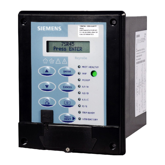
Using the Relay Fascia 4.4 Overview of Operator Elements and Display Elements Overview of Operator Elements and Display Elements Operation Panel of the Device [le_7SR45_OperInter, 1, --_--] Operating state display Local flag Keypad LED indicator label USB port cover 5 non-programmble LEDs and 4 user-programmable LEDs The following table provides a detailed explanation of the function of the operator and display elements. - Page 50 Using the Relay Fascia 4.4 Overview of Operator Elements and Display Elements Operator Element/Display Element Function Navigate the menu structure or to increase the param- eter value in the edit mode. Navigate the menu structure or to decrease the parameter value in the edit mode. To reset the fault indication on the fascia.
- Page 51 Using the Relay Fascia 4.4 Overview of Operator Elements and Display Elements Operator Element/Display Element Function LED 4 to LED 7 LEDs L4 to L7 are user-programmable LEDs. They indi- cate when the respective mapped function is trig- Default Value gered.
-
Page 52: Structure Of The Menu
Using the Relay Fascia 4.5 Structure of the Menu Structure of the Menu Relay Menu 4.5.1 Setting Mode This mode allows you to view and change settings in the relay. Instrument Mode This mode allows you to view the following conditions of the relay: •... -
Page 53: Setting Mode
Using the Relay Fascia 4.5 Structure of the Menu Setting Mode 4.5.3 The SETTING MODE is reached by pressing the READ DOWN(▼) or by pressing the ENTER key from the Relay Home Screen/Identifier Screen. Once the setting mode is reached, you can navigate into the settings mode submenus. Each submenu contains the configurable settings of the relay in separate groups. -
Page 54: Fault Data Mode
Fault Data Mode 4.5.5 The 7SR45 Argus Relay stores a maximum of 10 fault records. Each stored fault data can be viewed by pressing the TEST/RESET▶ key. Each record contains data of the operated elements, analog values, and LED status at the time of the fault. -
Page 55: Menu Tree
Using the Relay Fascia 4.5 Structure of the Menu Menu Tree 4.5.6 [dw_menu-structure, 2, en_US] (1) Available for 7SR45 Argus Dual Powered Relay. (2) For 7SR450[1/3]-xGA10-1AA0 variant, the multiple settings group and relay modes are not available. Reyrolle, Operating, Manual C53000-B7040-C101-1, Edition 08.2020... -
Page 56: Notification Alerts
4.6 Notification Alerts Notification Alerts Fault Alert (Trip Alert) 4.6.1 When the 7SR45 relay detects any fault, the LCD pop-ups the fault alert. The latest message updates or replaces any earlier alert pop-up messages. Alarm Alert 4.6.2 The alarm alert appears when any binary input is configured for general alarm and it is triggered. -
Page 57: Parameter Edit Screen
This alert appears when the relay is powered with auxiliary power supply. 4.6.4 Parameter Edit Screen 7SR45 Argus Relay allows you to edit the parameter value in the LCD. To edit any parameter, follow the procedure: From the Relay Identifier screen, navigate to the Parameter screen. ²... - Page 58 Reyrolle, Operating, Manual C53000-B7040-C101-1, Edition 08.2020...
-
Page 59: Using Reydisp Evolution
Using Reydisp Evolution General Connecting to the Relay for Setting via Reydisp Evolution Reyrolle, Operating, Manual C53000-B7040-C101-1, Edition 08.2020... -
Page 60: General
Reydisp Evolution is a Windows based suite of software tools, providing the means for the user to fully configure the 7SR45 Argus relay. The setting configuration tool allows the user to apply settings, interrogate settings and retrieve events from the device. It is compatible with Microsoft Windows XP SP3 or later, Windows Vista, and Windows 7 and 10. - Page 61 Using Reydisp Evolution 5.1 General Usability Features • Save to & open from disk • Printing • Windows clipboard functions • Configurable button bar • Configurable confirmation safety options Reyrolle, Operating, Manual C53000-B7040-C101-1, Edition 08.2020...
-
Page 62: Connecting To The Relay For Setting Via Reydisp Evolution
Using Reydisp Evolution 5.2 Connecting to the Relay for Setting via Reydisp Evolution Connecting to the Relay for Setting via Reydisp Evolution When Reydisp Evolution software is running, all available communication ports will automatically be detected. On the start page toolbar, open the sub-menu File and select Connect. The Connection Manager window will display all available communication ports. -
Page 63: In Service Operation
In Service Operation Overview Safety Notes Operation Options Modes of Operation Online Operation using Reydisp Indications Logs Edit Measured and Metered Values Change Device Settings 6.10 Settings Group Selection Reyrolle, Operating, Manual C53000-B7040-C101-1, Edition 08.2020... -
Page 64: Overview
In Service Operation 6.1 Overview Overview This section describes the handling of a 7SR45 Argus relay in the operating state. It contains the following information: • Reading information from the device • Using the functions of the device when in service Reyrolle, Operating, Manual C53000-B7040-C101-1, Edition 08.2020... -
Page 65: Safety Notes
In Service Operation 6.2 Safety Notes Safety Notes Authorized Operational Crew DANGER Danger due to inadmissible or improper operator control actions. Noncompliance with the safety notes will result in death or severe injuries. Only personnel who are skilled electricians with precise knowledge of the system may operate devices ²... -
Page 66: Operation Options
In Service Operation 6.3 Operation Options Operation Options General 6.3.1 The device is operated via a PC with Reydisp Evolution or directly on the relay fascia. You have the following operating options during operation: • Readout of indications • Readout, backup, and deletion of event logs, battery profile, and fault records •... -
Page 67: Modes Of Operation
• Battery The 7SR45 Argus Relay is powered primarily from auxiliary voltage even if all other power sources are avail- able. In the absence of auxiliary voltage, the relay is powered through phase currents. In the absence of both auxiliary voltage and phase currents, the relay can be powered on by USB or battery. - Page 68 In Service Operation 6.4 Modes of Operation [dw_7SR45 sensitivity (binary outputs), 3, en_US] Figure 6-1 Sensitivity for 1-Phase Fault with Binary Output Reyrolle, Operating, Manual C53000-B7040-C101-1, Edition 08.2020...
- Page 69 In Service Operation 6.4 Modes of Operation [dw_7SR45 sensitivity (pulse outputs), 3, en_US] Figure 6-2 Sensitivity for 1-Phase Fault with Pulse Output NOTE Multi-phase current improves the sensitivity. NOTE The removal/drainage of both main battery and RTC battery will delay sensitivity of the product. The presence/non-drainage of main battery and removal/drainage of the RTC battery will not impact the sensitivity of the product.
-
Page 70: Usb
6.4.5 The 7SR45 Argus relay has 2 batteries: a main battery CR123A and a coin cell RTC battery CR1632. This section is applicable to the main battery CR123A, 3 V 1400 mAh Li non-rechargeable battery . The battery is used to energize the device when auxiliary voltage or phase current or USB are not available. -
Page 71: Sleep Mode
Sleep Mode The 7SR45 Argus Relay goes into sleep mode when the auxiliary power/CT power, and USB power are not available. When the relay is in sleep mode, you can access the LCD by pressing the BAT ON/OFF key. In case of inactivity, the relay goes to the sleep mode after 60 s. - Page 72 6.4 Modes of Operation NOTE Siemens recommends replacing the battery when the LOW BATTERY indication is displayed. In the low battery mode, the following relay operations lead to insufficient operating voltage. The LCD displays the INSUFFICIENT ENERGY message and the relay enters the sleep mode.
-
Page 73: Online Operation Using Reydisp
Online Operation using Reydisp Reydisp Evolution Configuration Software 6.5.1 For more information about the Reydisp Evolution configuration software, visit the Siemens internet site www.siemens.com/reyrolle. Download Reydisp Evolution Set up and install Reydisp Evolution to access the Help menu. Refer to 7SR45 Argus relay Engineering Guide (C53000-G7040-C102-1) for more information. -
Page 74: Indications
In Service Operation 6.6 Indications Indications General 6.6.1 During operation, indications deliver information about operational states. These include: • Measured data • Device supervisions • Device functions Data records are stored in the non-volatile memory. The Data Storage menu contains the settings for clearing events and faults. -
Page 75: Displaying Indications
In Service Operation 6.6 Indications [sc_events_faults, 1, --_--] Figure 6-3 Event Record You will find additional information about deleting and saving logs in 6.7.2 Saving and Deleting the Logs. Displaying Indications 6.6.3 Displayed indications in Reydisp and on the on-site operation panel are supplemented with the following information: Table 6-2 Overview of Additional Information... - Page 76 In Service Operation 6.6 Indications Reset via Communication Protocol You can initiate acknowledgment of stored indications also via communication through a connected substa- tion automation technology system. This can occur in conformance to standards (Modbus RTU, IEC 60870-5-103) or via configuration (mapping) of the LED reset input signal for any protocol. Stored LEDs, output contacts, and spontaneous fault displays are reset.
-
Page 77: Logs
In Service Operation 6.7 Logs Logs Data Storage 6.7.1 The relay stores 2 types of data: Fault records, event records. Data records are stored in the non-volatile memory. The Data Storage menu contains the settings for clearing events and faults. Fault Records (Trip Log) The fault records are generated when the protection function detects a fault condition and the trip alert message appears on the LCD. -
Page 78: Saving And Deleting The Logs
The stored events can be cleared by using the DATA STORAGE > Clear Events setting in the HMI or from Reydisp. NOTE Before you delete the content of a log on your 7SR45 device, save the log with Reydisp Evolution on the hard disk drive of your PC. NOTE... -
Page 79: Edit Measured And Metered Values
Edit Measured and Metered Values Overview of Measured and Metered Values 6.8.1 The 7SR45 devices have numerous measured and metered values. The following Table 6-4 gives you an over- view of the scope and sequencing principle. Measured and metered values are referred to hereafter as meas- ured values. -
Page 80: Change Device Settings
Setting Time and Date You can set the date and time of your 7SR45 device using the relay fascia as well as Reydisp Evolution. Settings on the Device Using the On-Site Operation Panel To reach the settings for date and time from the main menu, use the navigation keys on the on-site operation panel. - Page 81 In Service Operation 6.9 Change Device Settings [sc_control_settime, 1, --_--] Figure 6-5 Set Time and Date Reyrolle, Operating, Manual C53000-B7040-C101-1, Edition 08.2020...
-
Page 82: Settings Group Selection
When the settings group or any setting parameters is changed, the relay restarts to apply the new settings and the protection is not active for the moment. NOTE Only one setting group is available for the MLFB 7SR450[1/3]-xGA10-1AA0 variant. Only in 7SR45 dual powered relays Reyrolle, Operating, Manual C53000-B7040-C101-1, Edition 08.2020... -
Page 83: Commissioning
Commissioning Overview Test Suite Integrated in the Device Initial Startup Precommissioning Tests Testing Readiness for Operation Reyrolle, Operating, Manual C53000-B7040-C101-1, Edition 08.2020... -
Page 84: Overview
Commissioning 7.1 Overview Overview This section contains information about the commissioning of the 7SR45 device. Test functions integrated in the device support you during testing, simplify testing processes, and reduce testing times. The secondary test is used for checking: •... -
Page 85: Test Suite Integrated In The Device
Commissioning 7.2 Test Suite Integrated in the Device Test Suite Integrated in the Device Testing Protection Functions 7.2.1 The purpose of this test is to verify the correct setting of protection functions and the routing of signals. To do this, you can feed the test signals with test equipment. Digital test equipment offers you multiple test programs and test sequences. -
Page 86: Initial Startup
Commissioning 7.3 Initial Startup Initial Startup Establishing Readiness for Operation State It is assumed that you have gone through steps in chapters 1 to 4. Check the connection of the auxiliary power supply if it is a dual powered relay (type1: DC 24 V to 60 V and type2: AC 60 V to 240 V/ DC 60 V to 240 V) or phase CT connection if it is a self powered relay. -
Page 87: Precommissioning Tests
Commissioning 7.4 Precommissioning Tests Precommissioning Tests Secondary Tests In the numerical relay test kits, select the appropriate burden (VA) for testing the relay functionalities. The following settings must be configured on the relay during testing. Parameters Settings System frequency Set nominal frequency CT/VT CONFIG Set phase CT and earth ratio FUNCTION CONFIG... -
Page 88: Testing Readiness For Operation
Startup. The device is ready for operation. If devices are built into cabi- nets, additional wiring and communication connections are necessary. Siemens recommends the following procedure in this order: Testing Binary Inputs and Outputs Check that the connection from the output of the testing equipment to the device is correct and the binary inputs and outputs are connected correctly. -
Page 89: Device Maintenance
Device Maintenance Execute Checks Self Monitoring General Information Troubleshooting Replace and Return Defective Device Firmware Update Reyrolle, Operating, Manual C53000-B7040-C101-1, Edition 08.2020... -
Page 90: Execute Checks
Device Maintenance 8.1 Execute Checks Execute Checks Protection-Function Test 8.1.1 General NOTE When performing a protection-function test, make sure that it does not lead to any undesired tripping. Likewise no information must be transmitted to a higher-level systems control where the operator may incorrectly interpret it. -
Page 91: Self Monitoring
The relay is functional only when the setting error message is acknowledged. NOTE If the device is faulty due to a Card error and/or MLFB error, it must be returned via the standard Siemens returns process. Contact your regional office. - Page 92 Internal supply voltage error 00010000 – Unexpected error 00100000 – NOTE If a binary output is assigned to IRF, Siemens recommends not to use the same binary output for any other protection function configuration. Reyrolle, Operating, Manual C53000-B7040-C101-1, Edition 08.2020...
-
Page 93: General Information
8.3 General Information General Information No special maintenance is required for 7SR45 devices. The only maintenance measure is to replace batteries. Since the device is mainly self-monitoring, hardware and software errors are automatically forwarded. This action minimizes any downtime of the device. It also eliminates the need for frequent maintenance inspec- tions. -
Page 94: Troubleshooting
² Read out the version of the installed firmware. ² Read the device related log (settings files, fault records, event records, IRF statuses) of 7SR45 device with ² Reydisp so that the support employee has all the necessary information. Reyrolle, Operating, Manual... -
Page 95: Replace And Return Defective Device
When returning the device ensure the protective film is inserted between the battery and the battery clip. Pack the complete device. ² In order to return the device to Siemens factory or any Siemens location, contact the customer support ² center and follow the instructions specified by them. -
Page 96: Firmware Update
Do not disconnect the USB when the firmware update is in progress. If the firmware update is terminated intermittently, the existing firmware corrupts in the relay and the relay stops working. The following alert appears when the firmware is updated and when the 7SR45 Argus Relay is loaded with 2438H80001R2x-1x firmware. -
Page 97: Security Settings
Security Settings Confirmation ID (Password Feature) Reyrolle, Operating, Manual C53000-B7040-C101-1, Edition 08.2020... -
Page 98: Confirmation Id (Password Feature)
Siemens customer support representatives and the confirmation ID can be retrieved. The 7SR45 Argus relay allows you to set the confirmation ID via SETTING MODE > SYSTEM CONFIG > Pass- word. The length of the confirmation ID must be 4 characters. -
Page 99: A Appendix
Appendix Revision History Reyrolle, Operating, Manual C53000-B7040-C101-1, Edition 08.2020... -
Page 100: Revision History
Appendix A.1 Revision History Revision History Software Revision History • 2020/08 2438H80001R2f-1a Protection function 51-1 setting range change to 0.1 ⋅ I rated 2.0 ⋅ I rated • User-Programmable LED feature added 2020/05 2438H80001R2e-1b Software maintenance 2019/12 2438H80001R2e-1a Thermal overload protection function (49) added 2019/05 2438H80001R2c-1b Software maintenance to suit customer requirements... -
Page 101: Index
Index Electrical inspection 17 Event records (Event log) 77 Activating the battery 17 Alarm alert 56 Auxiliary voltage 67 Fault alert 56 Fault data mode 52, 54 Fault records (Trip log) 77 Firmware article number 48 Backup device 95 Firmware update 96 Battery 70 Follow-Up Inspection on a Device 16 Battery profile 54, 70... - Page 102 Index Installing transparent front cover 33 Instrument mode 52, 53 Internal relay failure 91 Safety notes 65 Internal supply voltage error 91 Secondary current 53 Self monitoring 91 Sensitivity 67 Setting error 91 Setting mode 52, 53 Settings group selection 82 Measured Values 79 Sleep mode 71 Misc.