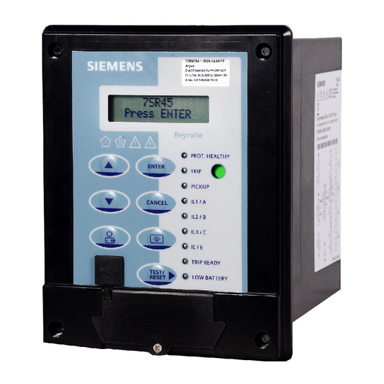
Siemens 7SR45 Argus User Manual
Self powered overcurrent and earth fault relay
Hide thumbs
Also See for 7SR45 Argus:
- User manual (120 pages) ,
- Device manual (118 pages) ,
- Manual (102 pages)

Related Manuals for Siemens 7SR45 Argus


Summary of Contents for Siemens 7SR45 Argus
- Page 1 Reyrolle Protection Devices 7SR45 Argus User Manual Self Powered Overcurrent and Earth Fault Relay...
- Page 2 © 2017 Siemens Protection Devices Limited...
- Page 3 Limited. No part of this document shall be reproduced or modified or stored in another form, in any data retrieval system, without the permission of Siemens Protection Devices Limited, nor shall any model or article be reproduced from this document unless Siemens Protection Devices Limited consent.
-
Page 4: Description Of Operation
Limited. No part of this document shall be reproduced or modified or stored in another form, in any data retrieval system, without the permission of Siemens Protection Devices Limited, nor shall any model or article be reproduced from this document unless Siemens Protection Devices Limited consent. -
Page 5: Table Of Contents
3.17 Self Monitoring ..........................32 3.17.1 Internal Relay Failure (IRF) ....................32 3.18 Data Storage ........................... 33 3.18.1 Fault Records (Trip Log) ..................... 33 3.18.2 Event Records (Event Log) ....................33 © 2017 Siemens Protection Devices Limited Chapter 1 Page 2 of 34... - Page 6 The following notational and formatting conventions are used within the remainder of this document: · Setting Menu Location MAIN MENU>SUB-MENU · Setting: Elem name -Setting · Setting value: value · Alternatives: [1st] [2nd] [3rd] © 2017 Siemens Protection Devices Limited Chapter 1 Page 3 of 34...
-
Page 7: Siemens Protection Devices Limited
7SR45 Description of Operation © 2017 Siemens Protection Devices Limited Chapter 1 Page 4 of 34... - Page 8 7SR45 Argus is “not in the battery power mode” and paper strip is inserted between the battery clip and battery. The lithium metal cells for 7SR45 Argus (as a spare part) are also subject to the special provision (SP)188 mentioned above, but classified according to: •...
-
Page 9: Section 1: Introduction
The relay functionality can be configured via a front USB port. By using the Reydisp evolution software, the user can update the settings and view the fault records (Trip Log) and events (Event Log). © 2017 Siemens Protection Devices Limited Chapter 1 Page 6 of 34... -
Page 10: Ordering Options
Instantaneous earth fault Time delayed phase fault overcurrent 51G/51N Time delayed earth fault 50LC/SOTF Switch-On-To-Fault Additional functionality No additional functionality Spare Spare 4 CT is configured as 3PF + EF © 2017 Siemens Protection Devices Limited Chapter 1 Page 7 of 34... -
Page 11: Functional Diagram
If possible, it is recommended to procure the battery as per the Table 1-1 from the local supplier or local market. Functional Diagram Figure 1-1 Functional Diagram of 7SR45 Self Powered Overcurrent and Earth Fault Relay © 2017 Siemens Protection Devices Limited Chapter 1 Page 8 of 34... -
Page 12: Terminal Diagram
The CT terminals are suitable for ring type lug connection and to provide a secure and reliable termination. Figure 1-2 Terminal Diagram of 7SR45 Self Powered Overcurrent and Earth Fault Relay © 2017 Siemens Protection Devices Limited Chapter 1 Page 9 of 34... -
Page 13: Section 2: Hardware Description
The rating label contains the following product Information: · Product name · MLFB ordering code, with hardware version suffix · Nominal current (In) rating · Rated frequency · Binary input supply rating · Serial number © 2017 Siemens Protection Devices Limited Chapter 1 Page 10 of 34... -
Page 14: Liquid Crystal Display (Lcd)
TURNS OFF due to the switching of power mode from USB or Battery to CT power. The back light can be TURNED ON again if sufficient current is available. For more information about power source, refer to Modes of Operation. Figure 2-3 Relay LCD © 2017 Siemens Protection Devices Limited Chapter 1 Page 11 of 34... -
Page 15: Keypad
Press CANCEL key repeatedly to return to the Relay Identifier screen. Used to switch-on and switch-off the relay with battery power when USB and CT power are not available. Used to switch-on and switch-off the backlight. © 2017 Siemens Protection Devices Limited Chapter 1 Page 12 of 34... -
Page 16: Light Emitting Diode (Led)
After the successful login and editing of parameter, password prompt screen does not appear till the login expires. If the user does not perform any operation for more than 1 minute, the login expires and unsaved settings will be discarded. © 2017 Siemens Protection Devices Limited Chapter 1 Page 13 of 34... -
Page 17: Software Version Menu
Serial No The serial number of the relay MLFB MLFB number of the relay Product Art No Unique number of the product assigned by SIEMENS Product Name Product name for display Alert Screen 2.5.1 Fault Alert When any fault is detected by the relay, LCD pops-up the fault alert. Any previous alert pop-up messages are updated or replaced by the latest message. -
Page 18: Parameter Edit Screen
To discard the parameter value, press the CANCEL key Press CANCEL till the user return to the Relay Identifier screen. Press ENTER to save the configuration in memory. © 2017 Siemens Protection Devices Limited Chapter 1 Page 15 of 34... -
Page 19: Section 3: Protection Functions (50, 51, 50N, 51N, 50G, 51G, 50Lc)
Instantaneous Overcurrent Protection (50-n) Parameters Description Default Value Step Change 50-n Element 50-n Block Disabled 50-n Setting Current Set point 0.2xIn 20xIn 50-n Delay Delay time 600 s 0.01 © 2017 Siemens Protection Devices Limited Chapter 1 Page 16 of 34... -
Page 20: Time Delayed Overcurrent Protection (51)
A fixed additional operate time can be added to the characteristic using 51-n Follower setting. Operation of the time delayed overcurrent elements can be inhibited by assigning binary inputs. Inhibit 51-n A binary input. Figure 3-2 Logic Diagram: Time Delayed Overcurrent Element © 2017 Siemens Protection Devices Limited Chapter 1 Page 17 of 34... -
Page 21: Instantaneous Derived Earth Fault Protection (50N)
50N-n Delay. Operation of the instantaneous derived earth fault elements can be inhibited from: Inhibit 50N-n A binary input. Figure 3-3 Logic Diagram: Derived Instantaneous Earth Fault Element © 2017 Siemens Protection Devices Limited Chapter 1 Page 18 of 34... -
Page 22: Time Delayed Derived Earth Fault Protection (51N)
Operation of the time delayed derived earth fault elements can be inhibited by assigning binary inputs. Inhibit 51N-n A binary input. Figure 3-4 Logic Diagram: Derived Time Delayed Earth Fault Protection © 2017 Siemens Protection Devices Limited Chapter 1 Page 19 of 34... -
Page 23: Instantaneous Measured Earth Fault Protection (50G)
Each instantaneous element has independent settings for pick-up current 50G-n Setting and a definite time delay 50G-n Delay. Operation of the instantaneous measured earth fault elements can be inhibited from: Inhibit 50G-n A binary input Figure 3-5 Logic Diagram: Instantaneous Measured Earth-fault Element © 2017 Siemens Protection Devices Limited Chapter 1 Page 20 of 34... -
Page 24: Time Delayed Measured Earth Fault Protection (51G)
Operation of the time delayed measured earth fault elements can be inhibited by assigning binary inputs. Inhibit 51G-n A binary input. Figure 3-6 Logic Diagram: Measured Time Delayed Earth Fault Element © 2017 Siemens Protection Devices Limited Chapter 1 Page 21 of 34... -
Page 25: Switch-On-To-Fault (50Lc/Sotf)
& Gn 50 LC Setting ³1 General Pickup Inhibit 50LC > > ³1 50LC > Gn 50 LC Measurement 10 cycles Figure 3-7 Logic Diagram: 50LC Overcurrent Element © 2017 Siemens Protection Devices Limited Chapter 1 Page 22 of 34... -
Page 26: Figure 3-8 Operating Time For Single Phase Fault With Binary Output
The multi-phase faults results to a shorter operating time. In the event of the battery going low or drained, the boot up time is increased by maximum of 25 ms. © 2017 Siemens Protection Devices Limited Chapter 1 Page 23 of 34... -
Page 27: General Alarm
Binary Input In the INPUT MATRIX configuration, LEDs and outputs can be reset by configuring the binary input. The configuration can be executed with ReyDisp Evolution or HMI. © 2017 Siemens Protection Devices Limited Chapter 1 Page 24 of 34... -
Page 28: Reydisp Software
In the Reydisp Evolution screen, navigate to Relay > Control and click Reset Flags. 3.9.3 TEST/RESET► Key From the Relay Identifier Screen, reset the LEDs and outputs by pressing the TEST/RESET► key. © 2017 Siemens Protection Devices Limited Chapter 1 Page 25 of 34... -
Page 29: Current Inputs
25 ms DO timers. Each binary input can be assigned to any binary output. This allows the relay to provide panel indications and alarms. Figure 3-12 Binary Input Logic © 2017 Siemens Protection Devices Limited Chapter 1 Page 26 of 34... -
Page 30: Binary Outputs
If the binary output is configured for protection trip or binary input operations it will act as “hand reset”. If the binary output is configured for other functions such as general pickup, protection healthy, and low battery, it will act as “self reset”. © 2017 Siemens Protection Devices Limited Chapter 1 Page 27 of 34... -
Page 31: Figure 3-13 Binary Output Logic
50LC/SOTF element operate General Pickup Pickup detected Prot'n Healthy Protection Healthy Low Battery Battery Volts low indication BI1 Operated BI-1 operated BI2 Operated BI-2 operated Internal Relay Failure © 2017 Siemens Protection Devices Limited Chapter 1 Page 28 of 34... -
Page 32: Binary Output Operation
If the minimum phase current is less than 0.1xIn in a three phase network and if the battery is in low or drained condition, there may be a time lag in the RTC performance. © 2017 Siemens Protection Devices Limited Chapter 1 Page 29 of 34... -
Page 33: Figure 3-14 Sensitivity For Single Phase Fault With Binary Output
When the device is started with the load current and the fault current appears within 10 AC cycles, then the operating time will be less than the calculated time. It is recommended to keep the Time Multiplier setting more than 0.1 © 2017 Siemens Protection Devices Limited Chapter 1 Page 30 of 34... -
Page 34: Usb Power
The low battery can be mapped to a binary output and can be used for low battery status indication. NOTE: It is recommended to replace the battery when the low battery indication is displayed. © 2017 Siemens Protection Devices Limited Chapter 1 Page 31 of 34... -
Page 35: Maintenance Mode
In case of Card Error and MLFB Error, the relay will not be functional and the relay should be sent to the factory. The following table displays the error messages and the error codes in the Instrument Mode. © 2017 Siemens Protection Devices Limited Chapter 1 Page 32 of 34... -
Page 36: Data Storage
· All the events can be uploaded over the data communications channel(s) and displayed in the ‘Reydisp’ package in chronological order and viewed in the sequence of events. © 2017 Siemens Protection Devices Limited Chapter 1 Page 33 of 34... -
Page 37: Real Time Clock
Do not disconnect the USB when the firmware update is in progress. If the firmware update is terminated intermittently, it may corrupt the existing firmware in the relay and the relay may stop from working. © 2017 Siemens Protection Devices Limited Chapter 1 Page 34 of 34... -
Page 38: The Copyright And Other Intellectual Property Rights In This Document, And In Any Model Or Article Produced From It
Limited. No part of this document shall be reproduced or modified or stored in another form, in any data retrieval system, without the permission of Siemens Protection Devices Limited, nor shall any model or article be reproduced from this document unless Siemens Protection Devices Limited consent. - Page 39 1.4 Instrument Mode ..........................4 1.5 Fault Data Mode ..........................5 List of Figures Figure 1-1 Menus............................3 Figure 1-2 Relay Identifier Screen ......................... 3 Figure 1-3 Menu Structure..........................5 © 2017 Siemens Protection Devices Limited Chapter 2 Page 2 of 5...
-
Page 40: Relay Menus
After entering the correct password, the user is allowed to configure the settings. If an incorrect password is entered, editing is not permitted. The user can view and navigate to all screens without knowing password. © 2017 Siemens Protection Devices Limited Chapter 2 Page 3 of 5... -
Page 41: Instrument Mode
Misc. meter displays the status of the auxiliary voltage input and IRF. For more information about IRF, refer to IRF table. BATTERY PROFILE The battery profile meter displays the status of the operations performed on the battery power. © 2017 Siemens Protection Devices Limited Chapter 2 Page 4 of 5... -
Page 42: Fault Data Mode
TEST/RESET► key. Each record contains data of the operated elements, analogue values, and LED status at the time of the fault. The data is viewed by scrolling down using the▼ key. © 2017 Siemens Protection Devices Limited Chapter 2 Page 5 of 5... - Page 43 2015/08 2438H80001R1a-1a First Release 2017/03 2438H80001R1a-1b Hardware maintenance 2017/03 2438H80001R1c-1a Software maintenance to suit customer requirements 2017/05 2438H80001R1d-1a Software maintenance to suit customer requirements 2017/06 2438H80001R1e-1a Software maintenance © 2017 Siemens Protection Devices Limited Chapter 3 Page 1 of 10...
- Page 44 Inrush Response Test (RTDS) ...................... 9 Table 1-17 50 Instantaneous & DTL OC & EF ....................10 Table 1-18 51 Time Delayed OC & EF ......................10 Table 1-19 50LC/SOTF ..........................10 © 2017 Siemens Protection Devices Limited Chapter 3 Page 2 of 10...
-
Page 45: Section 1: Performance Specification
Panel mounting, Non draw-out polycarbonate moulded case Enclosure IP 52 (front panel) IP 40 (enclosure sides) IP 20 (rear side) Depth is 203 mm Weight 1.8 kgs (appx) © 2017 Siemens Protection Devices Limited Chapter 3 Page 3 of 10... -
Page 46: Table 1-4 Terminal Blocks
19 V - 110 V DC Pick Up Delay User selectable 0 to 600 s (up to 10 minutes) Drop Off Delay User selectable 0 to 600 s (up to 10 minutes) © 2017 Siemens Protection Devices Limited Chapter 3 Page 4 of 10... -
Page 47: Environmental Performance
Sweep (@ a sweep rate of 1 octave/min) vibration in the frequency range (1 Hz - 35 Hz) at amplitude of 3.5 mm or 1.0 gn (whichever is less) © 2017 Siemens Protection Devices Limited Chapter 3 Page 5 of 10... -
Page 48: Table 1-12 Electrical Tests
30 MHz - 230 MHz, 40 dB µ V/m at 10 m measurement distance CISPR 11, Class A 230 MHz - 1 GHz, 47 dB µ V/m at 10 m measurement distance © 2017 Siemens Protection Devices Limited Chapter 3 Page 6 of 10... -
Page 49: Table 1-13 Climatic/Environmental Tests
(@ -40°C ) and accuracy test was performed and found to be within limits. The LCD was blank at -40°C. After accuracy test at -40° C, temperature was ramped up to room temperature and accuracy was found within limits, the LCD resumes to the normal condition. © 2017 Siemens Protection Devices Limited Chapter 3 Page 7 of 10... -
Page 50: Table 1-14 Product Safety Test
Terminal Mounting Class UL 94 V-0 Wiring (CT) (N)2GFAF (VDE) Components mounting Class UL 94 V-0 Enclosure Class UL 94 V-0 Class UL 94 V-0 Class UL 94 V-0 © 2017 Siemens Protection Devices Limited Chapter 3 Page 8 of 10... -
Page 51: Table 1-15 Real Time Digital Simulation Test (Rtds)
Test Conditions Simulated Inrush current with 15 % 2nd harmonic content Test Result The relay does not operate until fault current peak reaches 3 times the setting value © 2017 Siemens Protection Devices Limited Chapter 3 Page 9 of 10... -
Page 52: Performance Specification
0 s - 20 s Reset IEC/ANSI decaying, 0 s - 60 s Inhibited by Binary Input Table 1-19 50LC/SOTF Operate level 100% Is, ±5% Setting range 1,2,..20xIn © 2017 Siemens Protection Devices Limited Chapter 3 Page 10 of 10... - Page 53 2015/08 2438H80001R1a-1a First Release 2017/03 2438H80001R1a-1b Hardware maintenance 2017/03 2438H80001R1c-1a Software maintenance to suit customer requirements 2017/05 2438H80001R1d-1a Software maintenance to suit customer requirements 2017/06 2438H80001R1e-1a Software maintenance © 2017 Siemens Protection Devices Limited Chapter 5 Page 1 of 6...
- Page 54 Figure 1-1 7SR45 Clearance for Terminal Wiring ................... 3 Figure 1-2 Panel cut-out ..........................4 Figure 1-3 Battery Replacement ........................5 Figure 1-4 Removal of Paper Strip ......................... 6 © 2017 Siemens Protection Devices Limited Chapter 5 Page 2 of 6...
- Page 55 The earthing point (E) of auxiliary supply is connected to the ground (GND) point of the relay. The earth connection of relay casing should be solidly connected to the panel earth. Figure 1-1 7SR45 Clearance for Terminal Wiring © 2017 Siemens Protection Devices Limited Chapter 5 Page 3 of 6...
- Page 56 Dowell's/CP9/CP1 or equivalent terminals suitable for 2.5 mm (Terminal X3) 4 mm cable M3 ring type terminals suitable for Ground Terminal Dowell's/RS 613-9334 2.5 mm /4 mm cable © 2017 Siemens Protection Devices Limited Chapter 5 Page 4 of 6...
- Page 57 After the replacement of a new battery and in the absence of CT input, low input current, and without USB connection, test the relay by pressing BAT ON/OFF key to confirm the relay functionality. Figure 1-3 Battery Replacement © 2017 Siemens Protection Devices Limited Chapter 5 Page 5 of 6...
- Page 58 Open the 7SR45 self powered overcurrent and earth fault relay battery cover. To start the 7SR45 self powered overcurrent and earth fault relay, remove the paper strip between the battery clip and battery. Figure 1-4 Removal of Paper Strip © 2017 Siemens Protection Devices Limited Chapter 5 Page 6 of 6...
- Page 59 2015/08 2438H80001R1a-1a First Release 2017/03 2438H80001R1a-1b Hardware maintenance 2017/03 2438H80001R1c-1a Software maintenance to suit customer requirements 2017/05 2438H80001R1d-1a Software maintenance to suit customer requirements 2017/06 2438H80001R1e-1a Software maintenance © 2017 Siemens Protection Devices Limited Chapter 5 Page 1 of 3...
- Page 60 7SR45 Commissioning and Maintenance Guide Contents Section 1: Commissioning and Maintenance Guide ..................... 3 1.1 Troubleshooting ..........................3 © 2017 Siemens Protection Devices Limited Chapter 4 Page 2 of 3...
- Page 61 The relay may not have CT current inputs. LED is not glowing If the above troubleshooting checklist does not help in correcting the problem please contact the local Siemens office or contact customer support, Phone: +49 180/524 8437 (24hrs), Fax: +49 180/524 2471.
- Page 62 2015/08 2438H80001R1a-1a First Release 2017/03 2438H80001R1a-1b Hardware maintenance 2017/03 2438H80001R1c-1a Software maintenance to suit customer requirements 2017/05 2438H80001R1d-1a Software maintenance to suit customer requirements 2017/06 2438H80001R1e-1a Software maintenance © 2017 Siemens Protection Devices Limited Chapter 5 Page 1 of 6...
- Page 63 7SR45 Applications Guide Contents Section 1: Current Transformer Requirements ....................3 List of Figures Figure 1-1 Burden of the Relay for Different Currents ..................5 ©2017 Siemens Protection Devices Limited Chapter 6 Page 2 of 6...
- Page 64 The following graphs show the impedance of the relay for different currents when the relay is powered through a single phase current input. NOTE: When all the three phases are available, the burden on each CT reduces. ©2017 Siemens Protection Devices Limited Chapter 6 Page 3 of 6...
- Page 65 7SR45 Applications Guide ©2017 Siemens Protection Devices Limited Chapter 6 Page 4 of 6...
- Page 66 7SR45 Applications Guide Figure 1-1 Burden of the Relay for Different Currents ©2017 Siemens Protection Devices Limited Chapter 6 Page 5 of 6...
- Page 67 (typically 3 m) is short, the following are the recommended CTs to be used: · 2.5 VA, 5P10 or 5P20 for In = 1 A · 2.5 VA, 5P20 for In = 5 A ©2017 Siemens Protection Devices Limited Chapter 6 Page 6 of 6...
- Page 68 Phone: +44 (0)191 401 7901 Fax: +44 (0)191 401 5575 E-mail: marketing.spdl.gb@siemens.com EMEA-T10023-00-76GB June 2017 For enquires please contact our Customer Support Center Phone: +49 180/524 8437 (24hrs) Fax: +49 180/524 2471 E-mail: support.energy@siemens.com Subject to change without notice. Unrestricted Siemens Protection Devices Limited...