Table of Contents
Advertisement
Advertisement
Chapters
Table of Contents

Related Manuals for Suzuki MT50


Summary of Contents for Suzuki MT50
- Page 2 SUZUKIMT50R SUZUKIMT50J SUZUKIMT50K...
- Page 3 PREFACE SUZUKI Motorcycles, When it becomes necessary to replace parts on always use SUZUKI GENUINE PARTS which have passed a strict inspection which guarantees quality and performance. This parts catalogue covers the I ist of alI service parts for SUZUKI MT50R, MT50K.
- Page 4 Outside diameter Thickness Left hand side Width Right hand side Up to F.No.MT50-1234 5 -vF. No. 12345 F. No. I 2345-v From F.No.MT50-I2345 Figures in the remarks column show the dimensions of parts as follows: T ( or 4. INNER PARTS OF ASSEMBLY Parts number whitch has a period mark(.)
- Page 5 PLEASE OD NOT US E THE OLD ISSUE PARTS CATALOGUE AFTER RECEIPT NEW EDITION. WHEN ORDERING PARTS, ALWAYS REFER TO THE NEWEST EDITION OF PARTS CATALOGUE IN ORDER TO OBTAIN A RIGHT PARTS WITH OUT TROUBLE. MT50...
- Page 7 MTSOR MTSO � MTSOK ® MT50...
- Page 8 MT50...
- Page 9 MT50...
- Page 11 C 'l L l N O E...
- Page 12 CYLINDER - CRANKCASE Descrip t ion Q• t y Remarks Ref . . No. Part MTlOR MTlOJ MTlOK 11111-19001 CYLINDER HEAD 11141 -14000 GASKET 11211-19001 CYLINDER 11 241 -19000 G ASKET 08322-21068 WASHER 08311 -11 068 01421-06958 STUD BOLT 11306-19802 ASSY CRANKCASE 11481-19000...
- Page 13 C R J\ N K C J\ C 'i L l N O E...
- Page 15 CRANKCASE COVER...
- Page 16 SCREW WASHER 08322-11068 11381-01000 CAP, generator inspection SCREW 02111-05087 PLUG 09247-14001 GASKET 09168-14002 09308-07003 GROMMET OIL LEVEL PLUG 09128-06004 09168-06001 GASKET OIL PLUG 09259-20003 09250-14002 CAP, carburetor hole 11440-27200 COVER, carburetor to p 02112-05168 SCREW 15859-19000 PROTECTOR, fuel hose MT50...
- Page 18 09263-12003 ·BEARING 12xl6xl6 12211-19000 crank L: 14 ·PIN, guide 12511-06100 PLATE, 09180-20017 20x28x4.5 S PACER 09269-20006 BEARING 20x47xl4 09283-20011 I L SEAL 20x37x8 1 7x23x9 09180-17026 SPACER 09283-23001 OIL SEAL 23x47x8 08113-63030 BALL BEARING - 3 - 1 - MT50...
- Page 19 PISTON - CRANKSHAFT ---- MT50...
- Page 20 Descrip t ion Remarks MTlOR MTlOJ MTlOK 09180-17027 SPACER 17x28x4.5 21-1 21111-19501 primary drive GEAR, NT:21 21-2 21111-19002 primary drive GEAR, NT:21 09166-14008 WASHER 09140-14002 08341-31039 13150-19013 REED VALVE ASSY 13156-19001 reed valve GASKET, 02121-05167 SCREW -3- 2 - MT50...
- Page 22 ·ADJUSTER, 13688-08010 ·CAP 13417-01010 ·SPRING 13269-01010 pi lot ·SCREW, 13268-01010 ·SPRING needle 13370-13110 ·VALVE ASSY, 13392-01010 ·GASKET needle 09494-00049 E - 0 ·JET, 09492-17002 pi lot # 1 7.5 ·JET, 13254-01010 ·PIN, 13252-06110 ·FLOAT 13251-01011 ·GASKET -4- 1 - MT50...
- Page 23 .CARBURETOR 0- , 2 /-/1 r . / a -/ 1 � 1 1 . ®- 'D .... . -� � - / .._ . � - - - 20 � � � MT50...
- Page 24 ·GASKET 13249-05010 13247-05010 ·PLUG, drain ·JET, main #102.5 27-1 09491-20004 JET, main 27-2 09491-90003 #92.5 09491-92001 JET, main 27-3 JET, main #105 27-4 09491-21003 #107.5 27-5 09491-21006 JET, main main #110 27-6 09491-22004 JET, - 4 - 2 - MT50...
- Page 25 MU FF LE R AI R CL EA NE R - MT50...
- Page 27 OIL PUMP � MT50...
- Page 29 CLUTCH MT50...
- Page 30 WASHER 09140-16001 10-1 09443-07015 SPRING 10-2 09443-07009 SPRING clutch drive 21441-19001 PLATE, clutch driven 12-1 21452-19000 ADJUSTER, (O'V3) 12-2 21453-19000 utch driven ADJUSTER, (0'V3) clutch driven I .6 21451-19001 PLATE, (2'V5) 21443-19000 clutch driven outer PLATE, T:2. 09381-00001 CIRCLIP MT50...
- Page 31 TRANSMISSION �� � MT50...
- Page 32 02121-06108 SCREW 24131-19001 DRIVESHAFT 24321-19002 NT:32 GEAR, 2nd driven 08211-17301 THRUST WASHER 08113-63030 BEARING 09283-17006 OIL SEAL 17x40x7 18-1 27511-19000 SPROCKET, engine NT: 13 18-2 27511-19700 NT: 14, SPROCKET, engine 27512-19000 PLATE, engine sprocket 09111-06007 BOLT MT50 -8-1-...
- Page 33 TRANSMISSION MT50...
- Page 34 ( #420x 8 2U 27600-04011 #420x92L CHAIN ASSY, drive 27620-01011 chain JOINT ASSY, 06111-05004 BALL STEEL 09381-30001 Cl RCLI P 09167-26001 WASHER NT:29 24331-19001 driven GEAR, NT:46 24310-19002 GEAR, driven NT:26. 26260-19001 kick idle GEAR, - 8 - 2 - MT50...
- Page 35 GEAR SHIFTING t- 28 @L-- 2 9 20 1 9...
- Page 36 37721-05100 BODY, 02111-04168 SCREW 08322-21038 WASHER 02111-03058 SCREW 3 1 x38xl2.7 09263-31002 BEARING 09261-04002 OD: 4, 3. 8 ROLLER 09201-04003 25322-02000 HOLDER, 02122-06208 SCREW gear shifting cam 25341-02000 GUIDE, 09169-06003 WASHER 01112-06167 BOLT -9- 1 - MT50 ·"" ·.
- Page 37 GEAR SHIFTING t- 28 MT50...
- Page 39 KICK STARTER 20--i 19 ----© MT50 -10-...
- Page 40 KICK STARTER Description Q'ty Remarks Ref. No. Part MT50R MTlOJ MT50K kick starter 26211-05000 SHAFT, 09440-04010 SPRING 09209-05012 kick starter 26231-01000 PAWL, 26232-06000 kick starter pawl LIFTER, 09139-06002 SCREW 08211-12302 THRUST WASHER 09284-12006 OIL SEAL 26241-19002 kick starter drive NT:33 GEAR, 14x29x0.8 09160-14016...
- Page 41 FLYWHEEL MAGNETO 6·1 �r 4·5 1· 2 MT50 -I 1-...
- Page 43 SPEEDOMETER MT 50 -12-...
- Page 45 HEADLAMP -13- MT50...
- Page 46 LOCK WASHER 08312-11 088 HEXAGON NUT Note: are used for spare part parts marked a triangle (t.) parts New headlamp Ass'y. So when making order inner 1 4. old type headlamp Ass'y, refer to page on - 1 3 - MT50...
- Page 47 HEADLAMP MT50...
- Page 50 REAR COMBINATION LAMP Ref.No. Part Descrip t ion Q' t y Remarks MTlOR MTlOJ MTlOK 35001-27814-999 REAR COMBINATION LAMP SET � 35712-27630 ·LENS 35713-27630 ·GASKET 02111-04558 ·SCREW 35765-15010 ·CUSHION 35766-15010 ·SPACER 35970-31610 ·REFLEX REFLECTOR 08311-11058 ·NUT 08321-21058 ·LOCK WASHER 09471-06030 BULB 6V, 32/3cp 01112-06207...
- Page 52 · LENS 35712-27690 · SCREW 02111-04508 35715-29690 ·HOUSING 35765-15010 ·CUSHION ·SPACER 35766-15010 35970-31610 ·REFLEX REFLECTOR 08321-21058 ·LOCK WASHER 08311-11058 ·NUT BULB 6V, 21/3cp, US#I 154 09471-06009 01112-06207 BOLT 09160-06020 WASHER LOCK WASHER 08321-21068 08311-11068 GROMMET 09308-05005 GROMMET 09308-10004 MT50 -16-...
- Page 53 REAR COMBINATION LAMP MT50...
- Page 55 ELECTRICAL MT50 -18-...
- Page 56 0941 0-00014 CLAMP 09410-00022 HORN 38500-27031 SWITCH ASSY, 37740-20010 brake lamp SWITCH ASSY, brake 37740-27050 lamp SPRING 09443-06019 SPRING 09443-08010 LEVER, brake lamp switch 58182-27000 BRACKET, switch 58640-27000 brake lamp HOLDER, 58650-27000 bracket SCREW 02111-06087 LOCK WASHER 08321-21068 MT50 -18-...
- Page 57 FRAME - FRAME LH COVER 1-� MT50...
- Page 60 ·WASHER 42310-19000 PROP STAND 09443-14005 SPRING 09100-10007 BOLT, stand IOscrew prop 08312-31108 43510-27000 FOOTREST BAR, front 43612-03001 RUBBER, footrest 43610-03001 BAR, footrest rubber 19-1 09160-19006 WASHER 19-2 09160-19004 WASHER 09200-06010 04111-20208 COTTER PIN 01122-08168 BOLT 08321-21088 LOCK WASHER MT50 -20-...
- Page 61 FUEL TANK FUEL TANK COVER -21-1- MT50...
- Page 62 L:27.5 SPACER 21-1 44171-27000-184 COVER, fuel tank 21-2 44171-27600-546 tank COVER, fuel 21-3 44171-27610-906 COVER, fuel tank 68115-15600-019 TAPE, fuel tank cover 09128-06008 SCREW 09160-06007 WASHER 68111-27000 EMBLEM, fuel tank cover SUZUKI 68221-27000 pet name Hopper EMBLEM, MT 50 -21-1-...
- Page 63 FUEL TANK FUEL TANK COVER MT50...
- Page 64 FUEL TANK - FUEL TANK COVER Descrip t ion Ref.No. Part Q' t y Remarks MTSOR MTSOJ MTSOK 44174-27000 BREACE, fuel tank cover lower SCREW 09128-06008 LOCK WASHER 08321-21068 BAND, fuel tank rear 09462-00047 09386-10001 CLIP 44322-27000 Fl LTER, fue I -21-2- MT50...
- Page 65 \/ £. R R H c o £. P.. 1 M\ \<. O l l � '2 1 _---® '2 6...
- Page 66 COVER, 17-3 47111-27000-709 frame COVER, 47130-27000-019 frame cover KNOB, knob 09152-05101 NUT, 47151-27000 frame cover BOLT, 68171-26000 EMBLEM 45100-27000-369 SEAT ASSY 45220-27000 seat BRACKET, seat 45230-27000-019 KNOB, 09308-11002 seat knob GUIDE, 08311 -11 068 08321-21068 LOCK WASHER -22- MT50...
- Page 67 FRONT FORK -23- MT50...
- Page 68 51353-27000 ·NUT, fork upper 09104-10006 ·BOLT 51356-27000 fork ·WASHER, upper 09281-20001 ·OUST SEAL 51193-27000 ·CUSHION, fork 51571-27000 ·BOOT 09160-37002 ·WASHER 09205-04001 ·DOWEL PIN 51631-25000 NUT, steering stem 51611-20001 RACE, inner 51621-25000 RACE, outer 06111-06003 STEEL BALL 51643-25000 DUST SEAL MT50...
- Page 69 � '"T1 :::0 � ::E: I'TI I'TI (tfJ...
- Page 71 FRONT WHEEL MT50...
- Page 73 A B L E O N T R O L C E N D E R - C - f R O N T f H A N D L E B A R mB-- 2 5 - 25 - 1 - M T 50...
- Page 74 HAN DLEBAR - FRONT FEN DER - CONTROL CABLE Description Ref. No. Par t No . Q' t y Remarks MT50R MT50J MT50K 56110-27000 HANDLEBAR, 56150-27000 HANDLEBAR, 56220-27000 hand ebar KNOB, 56235-27001 handlebar STOPPER, 09381-28001 RING 56211-27000 handlebar stopper NUT, 56500-27010 rear view MIRROR ASSY,...
- Page 75 B L E O N T R O L C A E N D E R - C - F R O N T F H A N D L E B A R ---t) 2. 2. ffi!B-25 - 25 - 2 - M T 50...
- Page 76 HANDLEBAR - FRONT FENDER - CONTROL CABLE Q ' t y Descrip t ion Remarks Part Ref.No. MT50R MT50J MT50K 35950-18612 REFLECTOR REFLEX 35950-31010 REFLECTOR REFLEX 08311-11058 08321-21058 LOCK WASHER 09410-00030 harness CLAMP, wiring 09403-00042 CLAMP, rear brake cable - 2 5-2- MT 50...
- Page 78 ·SCREW throttle grip 57390-07011 ·ADJUSTER, 08311-11058 ·NUT 57211-20601 GRIP, 18-1 57500-27600 SWITCH ASSY, 18-2 57500-27210 SWITCH ASSY, LH dimmer switch 57320-01011 ·KNOB, switch knob spring 57334-01010 ·WASHER, 08322-21038 ·WASHER 08321-21038 ·LOCK WASHER 09125-03103 ·SCREW switch contact 57337-01010 ·SPRING, -26-1- MT50...
- Page 79 THROTTLE GRIP - RH SWITCH - LH SWITCH � MT50...
- Page 80 ·LEVER, brake LH 57435-20010 ·SPACER, lever ·LOCK WASHER 08321-21058 08311-11058 ·NUT 57370-01311 ·BUTTON, switch push 57382-01311 ·SPRING, switch push button 09125-05105 ·SCREW 01112-06128 ·BOLT · LOCK WASHER 08321-21068 58721-03011 ·LEVER, starter ·WASHER, starter lever wave 58722-03010 ·WASHER, starter lever 58723-03010 MT50...
- Page 81 REAR SWINGING ARM - REAR FENDER �-1 6 @--- 1 7 � 1 5 "( 4· 5 -27- MT50...
- Page 82 REAR SlJINGiNG ARt·1 �EAR FENDER Description Ref. No. Part Remarks MTIOR MT50J MT50K 61100-27801-184 SWINGING ARM SET, rear 61100-27801-137 SWINGING ARM SET, rear 61100-27801-709 SWINGING ARM SET, rear 09319-10009 ·BUSHING 61211-25001 SHAFT, swinging arm 09140-10001 08311-11108 08321-21108 LOCK WASHER 08322-21108 WASHER 62100-27000-184 SHOCK ABSORBER ASSY,...
- Page 84 64451-01002 LEVER, brake 64451-27000 LEVER, 09100-06050 BOLT 08322-21068 FLAT WASHER 08311-11 068 09160-12011 WASHER sprocket mounting 64611-27000 DRUM, rear 64650-27000 CUSHION, rear 64711-27000 AXLE, 64750-27000 axle SPACER, 09159-12102 09180-12039 SPACER 08123-62010 BEARING 08331-11458 RCL I P 09448-27003 SPRING -28-1- MT50...
- Page 86 LOCK WASHER 08312-11088 34-1 64511-27000 SPROCKET, rear �H 34-2 64511-27700 SPROCKET, rear N r: 29, 34-3 64511-27710 SPROCKET, rear NT:.30, 34-4 64511-27720 SPROCKET, rear NT: .3 I, 34-5 64511-27750 SPROCKET, rear �H: 32 01122-08128 BOLT 09169-08009 LOCK WASHER MT50 -28-2-...
- Page 89 OPTIONAL -30- MT50...
- Page 92 New on l y available 57421-20011 57421-20010 Ol d first, then new 57500-27210 57500-27010 then new 01 d first, 57621-27210 57621-20010 then new O l d first, 63110-27001-126 63110-27000-126 then new O l d first, 63110-27000-137 63110-27001-137 then new first, 61411-01601 61411-01001 MT50...
- Page 95 35136-()360(' 13-0(/ 47210-276�0-�46 1�-U6-2 35136··1961'1 13-06 lt•-05 t•56].'') 14-02 35151 13-03 3 51 54-·(� 56 ] (' 14-07 13-08. 35154-?.761(' 13.:. 0 �� 35155-·�132J. 1 '•- 0 3 14-0�� 3560J.-286_tP-99<; 29·01 35603-?.76lr-999 29-l)f< 35612-:261.) 29-0i' 356) 3-·i136l"� 29-03 29-lr'l MT50...
- Page 96 99000-11265 30-05-4 24 -lf3 5472l-276t)(' Q9000-Jl375 30-05-5 54781-;,�7000 24-30 � 99000-11845 30-05-6 24-21 55100-27011 99000-1_1895 30-05-7 28-25 99000-).7095 30-05-8 24-22 99000-?.5030 30-02 28-26 09000-32040 30-03 55312-27000-04(; 24-23 q9000-33010 30.-04 2A-27 ./5312-27000-046 55313-?7000-046 24-2t+ 28- 28 56110-27000 25-01 561.50-?7000 25-02 MT50...
- Page 97 O t.:' 3 21-21 ()6 8 16-09 02112-n61oe 6,-12 17-13 17-17 1)211 2-061 28 1-25-2 1P-02 11>-12 (\ 2 1 1 2 () 6 2 \) 8 2-16 25-28 u • 2 7 0211.2- · · 06258 2-09 � 26-).3 19-i MT50...
- Page 98 () q 2 6 ?, 0 t- 3 5-11 8-0� () 9 l 6 0 (, (H3331-:.1219 20- 1 9-1 0-..; 2 6 �$ 1 h 0 (• 2 3-lO Q833J- i_14'5P 28- 1 9 �� e-o? 09263-31002 9-14 "i MT50 - 5 -...
- Page 99 7,-]5 1 -9 2 ('lj (j 9 4-19 3 -01! 09<+92-1700? 093A1-i.2001 09381-28001 4- () 0 q-lB 09�\00-0013? C93F31-3000l e-24 19-lt:' Q9386-0AOol 21-lO 09blh-00001 19-14 30-06 09386�10001 ?1-31 091'.21-0000;:> 6..- }4 091·25-0000? ()9400-00107 30-07 25-3J. 09f'.26-0000J 30-('A 09403-00042 MT50...
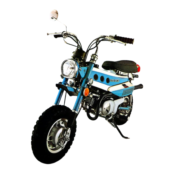
- Page 100 MT50 Suzuki has outstanding mechanism s such as reed val ve, Suzuki "C.C.I." system and automatic clutch. The engine performance has been improved especially in low speed and climbing abilit y .
- Page 101 RIGHT AND LEFT SIDE VIEWS...
-
Page 102: Table Of Contents
1. O U T S T AND I N G NEW ME C HAN I SM " R EED V AL V E EN G I NE" .... 2. R EV O L U TIONA R Y "SUZUKI C . C . I . "... -
Page 103: Outstanding New Mechanism "Reed Valve Engine
The size of the ports and timing of the ports are very important factors which determine the performance of the engine. The Suzuki MT50 engine has a reed intake valve and a third scavenging port, which result in ideal intake, scavenging and exhaust operations. - Page 104 1-2. Explanation of mechanism �EED VALVE SYSTEM IN THIS SYSTEM REED VALVE f..I CONTROLS t T AKE 9F FUEL AND PISTON CONTROLS EXHAUST OF BURNT GASES. '..REED VALVE OPENS. ALLCNV\NG EXHAUST PORT OPENS. PERMITTING COMPRESSED FUEl IN COMBUSTION SCAVEI'.GING PORT OPENS.
- Page 105 Piston valve Reed valve Closing When engine rpm. is low When engine rpm. is high Fig. 1-4 Comparison between piston valve and reed valve engines in intake port timing. The most important factors deciding engine performance are the intake of as much fuel as possible into the limited displacement of the cylinder and the completeness of the burning of the fuel.
- Page 106 Third Scavenging Port 1-5. Fuel stream Fuel stream · Scavengi ng port Sca venging port Third port Fig. 1-5 Comparision of scavenging streams In the conventional engine with both intake and exhaust ports in the cylinder wall, only two scavenging ports to transfer the fuel from the crankcase into the combustion char:nber can.
-
Page 107: Revolutionary "Suzuki C.c.i
Of the various lubrication systems for two-stroke engines, Suzuki C.C .I. developed by the Suzuki Motor C o., Ltd., the world's leading producer of two-stroke engines, is not only the newest but is quite the best by a large margin. - Page 108 2-3. Features of Suzuki C.C.I. Mixing of gasoline and oil is eliminated. Pure, fresh oil is supplied directly to the engine so lubrication efficiency is excellent.
-
Page 109: Automatic Clutch
In ordinary clutches, friction'between the plates is released by pulling a lever which controls the release mechanism. A wet, multi-plate, automatic clutch which utilizes centrifugal force to engage and disen gage the plates is installed in the Suzuki MT50. 3-2. Explanation of Meehan ism Fig. 3-1. Exploded view of clutch Attach a weight to a strip of rubber and twirl it at various speeds. -
Page 110: Specifications
Air cleaner Fuel tank capacity 2.5 ltr (0. 7/0.6 gal, US/Imp) Lubrication Sys te m special lubrication "Suzuki C.C.I." En gin e oi I bath, 550 cc (0.58/0.48 qt, US/Imp) Gearbox 0.8 ltr ( 1 .7 /1.4 pt , US/Imp) - Page 111 Ignition System flywheel magneto Ignition 20° ( 1.40 mm) before top dead center Ignition timing NGK BP-4H Spark plug Transmission System wet multi-disc, automatic centrifugal Clutch type 3-speed, constant-mesh Gearbox left foot, lever-operated return type Gear shifting • 3.84 : 1 (73/19) Primary reduction ratio (by gear) Final reduction ratio (by chain) 2.15 : 1 (28/13)
- Page 112 5. PERFORMANCE CURVES 5-1. Engine Performance Curves Mu. ootput .... 3 . 0HP/6,000r.p.m. m/5,500r.p.m. t or a ue .... 0.311< a (Xl OOO ) Crankshaft r.p.m. 5-2. Motorcycle Performance Curves X1000 � � � 4 .,:S flat road RIIUl ing resi stan ce Motorcycle .speed (kp/1)
- Page 113 6. TIPS ON OPERATION Please advise your customers to faithfully observe these tips to keep their MT50 in a peak condition and it will be ready to serve them with top performance at all times. 0 Breaking-in The life of the motorcycle depends greatly on the breaking in of the engine and the way the motorcycle is treated while it is new.
- Page 114 7. TROUBLE SHOOTING When trouble occurs with a motorcycle, it is important to find the source of the trouble as rapidly as possible. It is also necessary to perform only the work required to repair the machine. and not bother with parts which are functioning correctly. The list of possible troubles and their courses given below should help the service man to repair motorcycles qtJickly _without loss of effort.
- Page 115 3. Check to see that engine If engine compression is improper. compression is proper. (Turn engine with kick starter) 1. Worn cylinder and piston rings Repair or replace 2. Stiff piston ring on piston Repair or replace 3. Damage cylinder head gasket Replace 4.
- Page 116 Engine does not run smoothly at · high rpm. 1. Clogged or damaged fuel line Clean or replace 2. Dirty or improperly adjusted Clean and adjust spark plug 3. Improperly working contact Adjust breaker 4. Too late ignition (Retarded) Adjust 5.
- Page 117 Action Description Check Points Order 1. Check to see if oiling Adjust 1. Improperly adjusted oil pump control lever adjusting marks system is in good Remove air condition 2. Air in oil lines 3 . Choked oil tank breather pipe Correct Use prescribed oils 4.
- Page 118 7-6. Deffective Brakes First check the play in the front brake lever and the rear brake lever. Inspect the following points. Order Description Check Points Action 1. Insufficient braking 1. Worn brake linings Replace 2. Dirty brake linings Clean 3. Brake drum worn or dirty with Replace or clean mud or water 4.
- Page 120 19 . 09910-80112 Crankcase separating tool 09931-00110 Timing gauge check ignition timing 09900-27002 Timing tester check ignition timing hold engine sprocket 09921- 10 1 11 Engine sprocket holder As regards the details, refer to the Suzuki Special Tool Catalogue.
- Page 122 9. ENGINE CONTENTS 9- 1. Work with Engine in Frame ........21 9- 2.
-
Page 123: Work With Engine In Frame
9-1. Work with Engine in Frame Thes e parts can be inspected, adjusted and replaced without removing the engine from the frame. When removing the crankcase cover for repairing clutch, gear shifting shaft, etc, first remove the oil drain plug located on the bottom of the engine to n the oil from the gearbox and clutch chamber . -
Page 124: Work With Engine Removed From Frame
9-2. Work with Engine Removed from Frame Remove the engine from the frame into right left halves and separate the crankcase for these jobs. Parts Operation Inspect for shake, repair or replace; Check bearings for wear, Crankshaft replace; Check oil seals for leakage, replace Transmission Check gears and shafts, adjust or replace;... - Page 127 Unscrewing carburetor rubber cap screw Unscrew the four carburetor rubber cap screw Fig. 9-3-11 Unscrewing four carburetor rubber cap screws Removing· carburetor cover Remove the carburetor cover by loose ning three fitting bolts. Fig. 9-3-12 Removing carburetor cover Loosening carburetor clip bolt Loosen the carburetor clip bolt with flat head screw driver inserted...
- Page 128 Removing starter plunger Unscrew the starter plunger with 12 mm open wrench and pull it out of the plunger hole. Be careful not to lose the plunger and plunger spring after removed. Fig. 9-3-1 5 Remov ing star ter plunger Disconnecting muffler joint clamp Disconnect the muffler joint clamp and unscrew the rear muffler fitting...
-
Page 129: Tips On Assembling And Disassembling Engine
To install the engine into the frame reverse the order of removal. Connect wires according to the wiring diagram. Check the oil pump control lever adjusting marks. Inspect the clutch operation. 9-4. Tips on Assembling and Disassembling Engine The Engine is the heart of the motorcycle and consists of precisely manufactured parts, which must be handled and assembled most carefully. -
Page 130: Cylinder
9 -5-3. Installing Place the cylinder head gasket on the cylinder and then fit the cylinder head thereon, with the upper dome of its combustion chamber on the opposite side to the .exhaust port over the 4 studs. Place flat washer beneath each cylinder head nut. - Page 131 9-6-2 Inspecting Check the cylinder for wear. To determine the amount of wear measure the cylinder bore with a cylinder gauge. Measure the cy linder bore from front to back and from side to side at three points, mm (0.24 in) below the cylinder face (a), 9 mm (0.35 in) above...
-
Page 132: Piston Pin
9-6-3. Servicing Carbon deposits accumu l ated around the ex haust port increase resistance to the passage of exhaust gas and cause loss in engine power Remove carbon de and engine overheating. posits every 6,000km (4,000mi) with a scraper or screw driver. Be careful not to scratch or score the cylinder wall or passage surface. -
Page 133: Piston Pin Bearing
9-8. Piston Pin Bearing 9-8-1. Removing The piston pin bearing is installed on the con rod small end and its fit is loose, so it can be removed by hand. Fig. 9-8-1 Removing piston pin bearing 9-8-2. Inspecting To check the piston pin bearing for wear, fit the bearing into the small end of a new con... - Page 134 Checking wear and damage: Inspect the piston pin holes and piston ring locating pins for wear and the piston surface for burned spots, scratches, etc. Excessively worn locating pins allow piston rings to turn in the grooves and possibly catch on the ports of 1the cylinder.
-
Page 136: Piston Ring
Insta ll the secon d ring with the stam ped Second ring Top ring · mark "R" facing upward on it and finally the top ring to the top groove with the stamped mark "R" facing upward. When fitting the piston rings in the piston, take care of the following matters. -
Page 137: Drive Sprocket
Fig. 9-11-3 Disconnecting neutral indi Fig. 9-11-4 Unscrewing fitting screws cator switch wire Fig. 9-11-5 Removing magneto stator Fig. 9-11-6 Removing woodruff key 9-12. Drive Sprocket 9-12-1. Removing The drive sprocket is set as in the picture at right. Remove the two bo lts, match the teeth with the spline channels of the driveshaft, and pull it toward you;... -
Page 138: Neutral Indicator Switch
9-12-2. Inspecting lnspeet the engine sprocket teeth for wear. An excessively worn sprocket does not engage the drive chain properly and shortens the I ife of the drive chain. Replace the drive sprocket with a new one if excessively worn. 9-13. - Page 139 9-14-1. The dual-opening oil pump: The dual-openin g oil pump has been adopted in order that the required amount of oil can be pressure-fed to the necessary places. check valve Aligning marks Fi g . 9-14-3 Oil outlet pipe Fig. 9-14-2 Oil pump The oil, pressure-fed from the oil outlet pipe, drips from a nozzle directly in front of the reed valve.
- Page 140 9-14-3. Removing 9-14-6 Fig. Unscrewing oil pump Fig. 9-14-7 Unscrewing oil pump outlet union bolts fitting screws Fig. 9-14-9 Removing oil pump driving piece 9-14-11 Fig. Removing union bolt 9-14-10 Fig. Removing union bolt from crankcase left half from crankcase right cover Fig.
- Page 141 9-14-4. Inspecting and servicing Do not disassemble the oil pump as it is pre cision made and its pumping performance may change after it is reassembled. Expelling air Check the C.C.I. system for a1r especially when the oil pipes are disconnected for over haul or at periodical inspections.
- Page 142 B. Adjusting oil pump control cable. If the oil pump control wire is too taut, more oil is consumed and, not only will the engine become bad, but in some extreme cases, the throttle valve may not open completely. the other hand, if the control wire is too loose, it will affect the engine because the required amount of oil will not reach it.
-
Page 143: Clutch
9-15. Clutch The MT50 is equipped with a wet, multi-plate, automatic clutch which utilizes centrifugal force to engage and disengage the plates. Fig. 9-15-1 Clutch operation 9-15-1. Operation When the engine is stopped or running at low rpm, the rollers are pulled to the inside (2). - Page 146 •D Clutch housing : Construction clutch housing complete consists � i clutch housing ( 1), primary gear and pri mary gear fitting plate into which dampers are inserted and secured with screws as shown in Fig. 9-15-14. Checking for scoring Scores on the clutch housing slots catch the 9-15-14 Construction of clutch...
- Page 147 9-15-5. Servicing 1. Measure the clearance between the clutch inner plate and clutch inner cork plate. After the clutch is assembled, measure the clearance between the clutch in ner plate and clutch inner cork plate with a feeler gauge. Standard clearance is 1.4-1.8mm (0.055-0.071 in).
-
Page 148: Reed Valve
B. If engine rpm is too high: Clearance between the clutch cork plates and steel plates is larger than standard. The clutch rollers are arranged incorrectly. 9-16. Reed valve The reed valve is m?de of special steel so wear is very small. After long use,... - Page 149 Fig. 9-17-4 Removing kick sta· r ter shaft Fig. 9-17-5 Removing kick starter shaft return spring circlip B. Tips on in stalling When fitting the kick starter shaft return spring retainer and guide, pay attention to ( See Fig. 9-17-1.) their fitting direction.
- Page 150 A. Removing 9-17-9 Fig. Flattening shifting cam 9-17-10 Fig. Unscrewing shifting cam guide lock washer guide fitting bolt 9-17-11 Fig. Removing shifting cam 9-17-12 Fig. Removing shifting cam guide stopper B. Tips on installing Don't forget place the stopper \/1/aSher Stopper beneath the stopper, as it is easy to overlook.
- Page 151 9-17-3. Gear shifting shaft p awl return \Spring A. Inspecting Gear shifting shaft: Check the rivet calking of the shaft and arm joint to see if it is not loose. Replace the Shaft return shaft complete if its rivet calking is loose. Spring Gear shifting shaft return spring: A gear shifting shaft return spring which has...
-
Page 152: Crankcase
9-18. Crankcase 9-18-1. Disassembling Fig. 9-18-2 Loosening primary pinion Fig. 9-18-1 Straightening primary pinion washer Fig .. 9-18-3 Removing primary pinion Fig. 9-18-4 Removing woodruff key the primary pinion Note: When loosening nut, with the cylinder and piston in posit ion, u se a flywheel rotor holder (special tool_ 09930-40111) to pre... - Page 153 Special tool N o . 0 9910-08 112 Fig. Removing crankcase joining Fig. Separating crankcase 9-18-6 9-18-7 screw from left crankcase Note: When loosening the crankcase joining screw, be sure to loosen them bit by crisscross fashion. Use a crankcase separating tool {special tool to separate the crank...
- Page 154 9-18-3. Assembling Fig. 9-18-13 Fitting crankcase gasket dowel pins Fig. 9-18-12 Installing dowel pins Note: Install the crankshaft and gearbox com ponents in the crankcase right half. Checking to see that the two dowel pins are properly located, .fit the left half over the right half.
-
Page 155: Transmission
9-19. Transmission 2 3 12 Counter shaft L = 174.5 (6.87), NT= 11 Countershaft thrust I.D. = 21 (0.827), O.D. = 30 washer (1.18), T = 1.0 (0.04) Drive shaft L= 121 (4.77),NT= 16 Ball washer Second drive N.T. = 15 gear ·... - Page 156 Fig. 9-19-3 Gear positions at low speed Fig. 9-19-2 Gear positions at neutral Fig. 9-19-5 Gear positions at top speed Fig. 9-19-4 Gear positions at second speed Stee l ball 9-19-1. Operation Engine power is transmitted to the primary gear on the clutch housing by the primary pinion.
- Page 157 9-19-3. Inspecting Gears Inspect the transmission gears for wear or da mage to the teeth and rnternal bushings. inspect wear of the internal bushings, insert a relative new shaft into the gears. If they worn damaged excessively, replace them. Shifting fork grooves Fig.
- Page 158 9-19-4. Installing Place the crankcase right half on a work bench. Place the kick starter gear thrust washer on the kick starter gear pressed into the countershaft bearing. Place the thrust washer on the drive shaft fitting hole of crankcase and then the kick starter idle gear, with the flat surface down.
- Page 159 9-20. Kick Starter Mechanism Kick starter pinion Pawl roller Rubber bushing Pawl Thrust washer Thrust washer 00 � 30 (1.18 in) 00-29 (1.14 in) 10-12 (0.47 in) 10-14 (0.55 in) T-1.5 (0.06 in) T-1.5 (0.06 in) Kick starter shaft Screw Pawl spring Stopper Kick starter pinion left washer...
-
Page 160: Kick Starter Mechanism
Primary gear Primar y pinion Kick starter lever Kick starter shaft Kick starter pinion Fig. 9-20-2 Kick starter mechanism Inside the kick starter pm1on is installed a ratchet mechanism consisting of a pawl, pawl roller and pawl spring. When the kick starter lever is depressed, the kick starter shaft turns in a counterclockwise direction as seen from the lever end of the shaft. - Page 161 Once the engine is started and the kick starter lever is released, the kick starter shaft is returned to its original position by the return spring and the pawl is pushed back out of the way by the kick starter shaft stopper so that the engine revs are not transmitted to the kick starter shaft.
-
Page 162: Crankshaft
9-20-3. Tips on disassembling and assembl The kick starter shaft assembly can be remov ed from the crankcase easily by hand, but take care not to lose the thrust washers, kick pawl spring or kick pawl roller. When assembling the kick starter system, be sure to f it one thrust washer on either side of the kick starter shaft large section. - Page 163 The crankshaft assembly is supported by two ball bearings which are shrink-fitted in the crankcase. The left crankshaft bearing is lubricated by the oil supplied under pressure from the oil pump. The right crankshaft bearing is lubricated by the transmission oil. The Needle bearings are installed on the large and small ends of the connecting rod, assuring smooth turning and minimum wear.
- Page 164 B. Connecting rod small end shake: Rest the crankshaft assembly on a pair of V blocks and place the connecting rod at its top dead center. Place the extension foot of the dial gauge against the small end. Incline the connecting rod to the left as far as it wi II go and then to the right and measure the con...
-
Page 165: Gear Shifting Mechanism
9-22. Gear Shifting Mechanism Gear shifting cam stopper Top pinion Top gear 9-22-1 Fig. Gear shifting mechanism 9-22-1. Operation When the gear shifting lever is depressed, the gear shifting pawl on the gear shifting shaft pushes the gear shifting cam pin, turning the gear shifting cam. At this moment guided by the gear shifting fork guides which slide in the grooves machined on the cam drum, the gear shifting forks move in the axial direction, causing the top gear and top pinion to travel on the splines of the shafts so that low, second or top is selected. - Page 166 An anti-Jumping contrivance is designed into the gear shifting mechanism to prevent the gears from jumping over the position wanted due to rotational inertia of the gear shifting cam even when the gear shifting lever is operated with a rapid motion. When the gears are shifted up, the gear shifting shaft arm holds the gear shifting cam stopper at point "...
-
Page 167: Oil Seal
Short pin 2. Use new cotter pins every time they are removed. Be sure to insert cotter pins from the round side and bend their ends open tightly against the flat surface. 3. In case the shifting cam pins have been removed for some reason, first refit a short pin into the hole just on the opposite side neutral... - Page 169 9-25-2. Specifications � 1 0 5 Main jet 2.0 mm ¢> Air jet ..... 3 G9, clipped into 3 rd groove Jet needle .
- Page 170 from the float chamber at medium speeds from � to % throat opening. As the throttle valve is raised, the clearance increases due to the taperin g of the jet needle. Needle jet : The needle jet determines the amount of fuel in combination with the jet needle.
- Page 171 Starter plunger : The starter plunger is a kind of valve which controls the starter system. If it is raised, the passages for air and fuel are opened and a rich fuel/air mixture enough to start the coldest engine is dispensed. If it is lowered to the bottom, the passages are closed.
- Page 172 9-25-3. Disassembling Remove four fitting screws with a cross head screw driver and separate the float chamber body from the mixing chamber body. Remove the float from the mixing chamber body by pulling the float pin out by hand. Be careful not to bend or raise the float tongue which contacts the needle valve and Fig.
- Page 173 5. Check the tapered end of the needle valve for stepped wear. If the needle valve is worn, there will be left a gap between the valve seat and needle valve even when the fuel level in the float chamber rises and the float tongue pushes the needle valve, and an overflow will result.
- Page 174 9-25-5. Adjusting idling Preparations : Removing four fitting screws, slip the car buretor rubber cap up along cables. Make sure the ferrule of the throttle cable �heath is properly seated in the cable ad juster on the top of the carburetor. 3.
- Page 175 9-25-6. Adjusting fuel/air mixture A. Checking mixture: Too rich or too lean fuel adversely affects engine performance. The fuel/air mixture can be adjusted by adjusting carburetor settings. Check to see that fuel and air is properly mix 1. Symptoms of too rich a mixture a.
-
Page 176: Electrical Equipment
10. ELECTRICAL EQUIPMENT The electrical equipment such as flywheel mag neto, ignition coil, selenium rectifier, etc. on the MT50 is almost same on the K 1 OP, so please refer to the K 1 OP Service M anual for details. - Page 177 Connect meters in accordance with the connection diagram when checking the performance of the flywheel magneto. 10-3. Spark Plug Cross-Reference Table The standard s p ark plug for e MT50 engine is NG K BP-4H which is (0.55 in) in thread diameter and 12.7 mm...
- Page 178 Pointer moves. Pointer does not mova. Pointer moves. will be demagnetized Fig. 10-3 Inspecting selenium rectifier To check the selenium rectifier, wire circuits as shown in Fig. 10-3. (Turn the selector knob of a Suzuki pocket tester to "RX1 ".)
- Page 179 10-6. Battery Trouble Shooting If battery has tendency to get discharged If the battery often gets discharged and needs a supplemental charge, first check how the motorcycle is operated in order to determine whether its cause is in a rather extraordinary way of operation or in a defect in the charging system.
- Page 180 11. BODY · 1 1-1. ·Fuel Cock This fuel cock was specially designed for MT50 1n which the air vent for the fuel tank and the carburetor fuel passage are incorporated, in order to prevent fuel from flowing out of the fuel tank in such case as the bike is laid down on the carrier or car trunk room during transportation.
- Page 181 11-2. Wheel Rim The wheel rim can be separated to R.H. and L.H. halves to get easier operation when tire is repaired or replaced. Be careful when installing the front and rear wheel rims, put then in correct place of drums with the air inflating valves faced toward right side respectively. Otherwise, the wheels will be found off-set in the front and rear suspensions as shown Fig.
- Page 182 12. MAINTENANCE, INSPECTIONS AND ADJUSTMENTS Explanation 12-1. This section includes instructions on adjusting the motrocycle after assembling, and daily maintenance, inspections and adjustments. To have the motorcycle give good performance it is necessary to take care of the machine properly as outlined here. Engine Compressior' 12-2.
- Page 183 12-4. Adjusting Point Gap and Ignition Tim- After long distance of runs the contact points follower are worn, changing ignition timing. Incorrect ignition timing decreases engine per formance and shortens the life of the engine. So it is necessary to check the ignition timing periodically.
- Page 184 Checking timing with timing lamp : A kind of stroboscope called "timing lamp" is incorporated in a Suzuki electro tester. This timing lamp enables you to check the ignition timing dynamically.
- Page 185 Adjusting ignition timing : If it is found on inspecting the ignition timing that the piston is not at mm before tdc 1.56 or the timing marks are not aligned, adjust the ignition timing in the following way: Holding the flywheel rotor with a flywheel rotor holder (special tool 09930-401 1 1), remove the flywheel rotor nut with a...
- Page 186 12-7. Cleaning Air Cleaner If the air cleaner is clo gg ed with dust, a sufficient amount of air is not supplied to the en g ine causing power drop of the en g ine. Clean the air cleaner element by blowin g com pressed air.
- Page 187 12-11. Adjusting Drive Chain Always keep the drive chain play 15-20 (0"6-0"8 in) with the motorcycle propped on the cente r stand" To adjust the drive chain play, first loosen the two nuts on the rear axle and then turn both the right and l�ft adjuste r nuts Make sure marks on both chain adjusters...
- Page 188 12-14. Checking Inflation Pressure Keep tire inflation pressure proper at all times to prolong the I ife of the tires and for safe and comfortable ridin g . Solo ridin g Dual ridin g k g /sq em k g /sq em Front ( 14 lb/sq in)
- Page 189 Ref. No. Description O'ty Tightening torque Spark p lug 220 kg-em ( 190 I b-in, 16 lb-ft) Cylinder head nuts 100 kg-em ( 90 I b-in, 7 lb-ft) Steering handle adjusting ring set nuts 220 kg-em ( 190 I b-in, 6 lb-ft) Front axle nut 440 kg-em (386 lb-in, 31 lb-ft)
- Page 190 PERIODICAL INSPECTIONCHART The chart below indicates time when inspections, adjustments and maintenance are required based on the distance the motorcycle runs, that is first 1,000km (750mi), and every 3,000 km (2,000mi), 6,000km (4,000mi) and 12,000km (8,000mi) thereafter. According to the chart, advise users to make the motorcycle checked and serviced at your shop.
- Page 191 MTSO WIRING DIAGRAM rn signal indicator lamp (6V 1.7WI B: Neutral indicator lamp (6V 3W) ..Orange High beam ator lamp (6V 3W) .Vor .. Y J--- Speed o meter lamp (6V 3W) .., ..Yellow ..
- Page 192 EXPLODED VIEW OF MT50 ENGINE Spark Plug NGK BP-4H Ignition Timing: 20° ( 1.56mm) B.T.D.C. Gearbox Oil Capacity : 450cc (0.48/0.40qt, US/Imp) SUZUKI Recommended Oil If the temperature is below 1CfC(50°F) • SHELL 2T TWO STROKE OIL SUPER SHELL MOTOR OIL...
Need help?
Do you have a question about the MT50 and is the answer not in the manual?
Questions and answers