
Subscribe to Our Youtube Channel
Related Manuals for ABB GE Power Break II GEH6271


Summary of Contents for ABB GE Power Break II GEH6271
- Page 1 GEH6271 INSTALLATION INSTRUCTIONS Power Break® II Devices Draw Out 800–4000 Ampere Frames...
- Page 2 Features may be described herein that are not present in all hardware and software systems. ABB Industrial Systems assumes no obligation of notice to holders of this document with respect to changes subsequently made.
-
Page 3: Table Of Contents
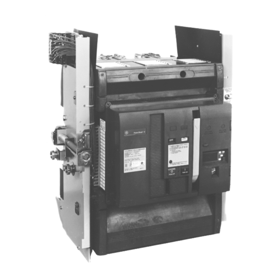
Power Break® II Devices Draw-Out Device Installation Table of Contents Description..................................... 1 Features....................................1 Installing the Device ................................3 Removing the Device ................................5 Maintenance Procedures ..............................6 Lubrication ....................................6 List of Figures 1. Rear view of the Power Break® II draw-out device......................1 2. -
Page 4: Description
Power Break® II Devices Draw-Out Device Installation Description Rollers. The rollers on the sides of the device ride on retract- Types SSD and SHD Power Break II draw-out circuit breakers able rails in the draw-out substructure for easy installation are used in types SPS and SPH substructures, with and removal. -
Page 5: Right Side Of The Device, Showing The Rejection Feature, Drawout Position Indicator, And Electric Operator Cutoff Switch
Power Break® II Devices Draw-Out Device Installation Substructure Breaker SSD08X 202, X204, X208 SSD08X SPSDOS08 SHD08X202, X204, X208 SPHDOS08 SSD16X210,X216 SPSDOS16 SHD16X210,X216 SPHDOS16 SSD20X220 SPSDOS20 SHD20X220 SPHDOS20 SSD25X210,X220,X325 SPSDOS25 SHD25X210,X220,X325 SPHDOS25 SSD30X330 SPSDOS30 Rejection SHD30X330 SPHDOS30 Feature SSD40X440 SPSDOS40 SHD40X440 SPHDOS40 Draw-Out Position... -
Page 6: Installing The Device
Power Break® II Devices Draw-Out Device Installation Installing the Device Pipe Use the following procedure to install the draw-out device into the substructure. Attach the Lifting Bar, catalog number TDOLB, by Lifting Bar locating the hooks on the bar beneath the shoulder Shoulder studs of the device, as illustrated in Figures 4 and 5. -
Page 7: Device Installed On Rails, Ready To Be Pushed Into The Substructure
Power Break® II Devices Draw-Out Device Installation Substructure Rejection Feature .06 in minimum Device Rejection Feature Compartment — Position Figure 6. Device installed on rails, ready to be pushed into the substructure. Indicator — Figure 8. Compartment position indicator on the front of the device. Racking Tool —... -
Page 8: Removing The Device
Power Break® II Devices Draw-Out Device Installation Removing the Device Use the following procedure to remove the draw-out device from the substructure. CAUTION: The device must be OFF before it is dis- connected and removed. ATTENTION: Le mécanisme doit être à OFF avant qu’il ne soit débroché... -
Page 9: Maintenance Procedures
Power Break® II Devices Draw-Out Device Installation Maintenance Procedures Check primary and secondary disconnecting surfaces for signs of abnormal wear or overheating. If required, A regular maintenance schedule should be established to clean contacts with a suitable solvent. Discoloration of obtain the best service and reliability. - Page 10 GE is a trademark of GE. Manufactured We reserve the right to make technical 305 Gregson Drive by ABB Inc. under license from GE. changes or modify the contents of this in the subject matter and illustrations Cary, NC 27511.
Need help?
Do you have a question about the GE Power Break II GEH6271 and is the answer not in the manual?
Questions and answers