RAM TRUS-T-LIFT Supplemental Manual
Hide thumbs
Also See for TRUS-T-LIFT:
- Installation manual (32 pages) ,
- Supplemental manual (11 pages) ,
- Supplemental manual (9 pages)
Table of Contents
Advertisement
Advertisement
Table of Contents

Related Manuals for RAM TRUS-T-LIFT


Summary of Contents for RAM TRUS-T-LIFT
- Page 1 TRUS-T-LIFT SUPPLEMENTAL MANUAL #1 SAFETY PAN & CARRIAGE GATE...
- Page 2 RAM Elevators + Lifts 1-800-563-4382...
-
Page 3: Table Of Contents
2.2: Additional Symbols ......................... 1 2.3: Safety Notes ............................. 2 Section 3: Safety Pan ..........................3 3.1: Installation ............................4 Section 4: Carriage Gate ........................... 6 4.1: Carriage Gate Diagram ........................7 4.2: Installation ............................8 1-800-563-4382 RAM Elevators + Lifts... -
Page 4: Section 1: Introduction
This supplemental manual has been provided to walk you through the safe and efficient installation of a Trus-T-Lift Carriage Gate and Safety Pan. Please read this manual, as well as the main installation manual, thoroughly before installing and operating your lift. We recommend your lift and any add-ons be installed and serviced by a qualified technician. -
Page 5: Safety Notes
The lift is intended for use by people and not to be used for cargo or other purposes. Lifting capacity is up to a maximum of 750 lb. unless otherwise noted on the lift and in RAM’s supplied documentation. (DO NOT OVERLOAD THE LIFT). Overloading the lift will render RAM’s warranty null and void. -
Page 6: Section 3: Safety Pan
Section 3: Safety Pan RAM Elevators + Lifts 1-800-563-4382... -
Page 7: Installation
1) Wire the safety pan into the bottom junction box of the lift as per the provided electrical schematics and wiring diagram, using protective conduit as per the applicable electrical code requirements. This junction box is connected to the guide frame, as shown below. 1-800-563-4382 RAM Elevators + Lifts... - Page 8 3) Set the platform’s mechanical stops ( A ) evenly such that they will stop the platform on the ground prior to the safety pan being activated. To ensure proper function, test the position of the mechanical stops at full load 4) Continue installation as normal from section 4.6 in the main manual. RAM Elevators + Lifts 1-800-563-4382...
-
Page 9: Section 4: Carriage Gate
Section 4: Carriage Gate 1-800-563-4382 RAM Elevators + Lifts... -
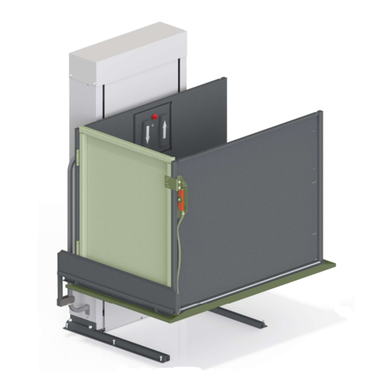
Page 10: Carriage Gate Diagram
4.1: Carriage Gate Diagram Gate Hinge Carriage Gate Door Gate Spring Hinge Interlock + Mounting Angle Interlock Tab & Gate Latch Interlock Cable RAM Elevators + Lifts 1-800-563-4382... -
Page 11: Installation
(for cars with safety pan ensure car is resting evenly on mechanical stops ). Fasten the door gate latch and interlock key tab to the gate door making sure to line up with the interlock head when the gate closes. 1-800-563-4382 RAM Elevators + Lifts... - Page 12 5) Run the interlock cable under the toe plate angle and fasten it there with provided nylon tie straps. If you have a safety pan, there are holes pre-drilled into the pan for the tie straps. RAM Elevators + Lifts 1-800-563-4382...
- Page 13 1-800-563-4382 RAM Elevators + Lifts...
Need help?
Do you have a question about the TRUS-T-LIFT and is the answer not in the manual?
Questions and answers
How can I purchase a lost 644 key