RAM Trus-T-Lift Installation Manual
Hide thumbs
Also See for Trus-T-Lift:
- Supplemental manual (13 pages) ,
- Supplemental manual (11 pages) ,
- Supplemental manual (9 pages)
Table of Contents
Advertisement
Advertisement
Table of Contents

Related Manuals for RAM Trus-T-Lift


Summary of Contents for RAM Trus-T-Lift
- Page 1 RESIDENTIAL TRUS-T-LIFT INSTALLATION MANUAL...
- Page 2 This page is left intentionally blank. RAM Elevators + Lifts 1-800-563-4382...
-
Page 3: Table Of Contents
5.1: Full Load Testing ................................26 5.2: Upper Limit and Upper Final Limit Switch ......................26 5.4: Lower Limit Switch ..............................27 5.5: Additional Testing Notes ............................27 5.6: Reinstalling the Front Cover ........................... 28 Section 6: Troubleshooting ............................29 1-800-563-4382 RAM Elevators + Lifts... - Page 4 Supplemental Manual #3 – Tall Tower”. For additional instructions for installing emergency operation devices such as a UPS or a Tower of Power, “Trus-T-Lift please see Supplemental Manual #4 – Emergency Operation Devices”. RAM Elevators + Lifts 1-800-563-4382...
-
Page 5: Lift Diagrams
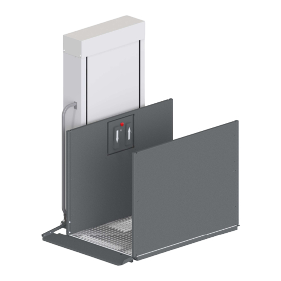
Lift Diagrams Top Cover Grab Rail Toe Plate Rocker Arm Toe Plate Front Cover Control Wall Control Box Handrail Wall 1-800-563-4382 RAM Elevators + Lifts... - Page 6 Lift Motor Drive Screw Guide Rail Tube Upper Limit Bracket Guide Frame Upper Limit Switch Lower Limit Switch RAM Elevators + Lifts 1-800-563-4382...
-
Page 7: Section 1: Introduction
Section 1: Introduction Thank you for selecting the Trus-T-Lift™. When operated properly, the Trus-T-Lift™ is designed to provide years of trouble-free service. This manual is provided to walk you through installation safely and efficiently. Please read this manual thoroughly before installing and operating your lift for the first time. -
Page 8: Section 2: Safety Information
The following are additional symbols and conventions used through the manual: Detail callout, used to call attention Step Callout, labels which step to a detailed mentioned in the body the given diagram relates to of the instructions. RAM Elevators + Lifts 1-800-563-4382... -
Page 9: Safety Notes
The lift is intended for use by people and not to be used for cargo or other purposes. Lifting capacity is up to a maximum of 750 lb. unless otherwise noted on the lift and in RAM’s supplied documentation. (DO NOT OVERLOAD THE LIFT). Overloading the lift will render RAM’s warranty null and void. -
Page 10: Section 3: Pre-Installation
3/8” Socket ratchet 15/16” Socket Note Keep the manual crank components in a safe place near the lift, as in the event of an emergency, you may need them to manually lift or lower the platform. RAM Elevators + Lifts 1-800-563-4382... -
Page 11: Table Of Provided Fasteners
3/4" Long 3/16” ID, 9/16” OD Galvanised Steel White Plastic Wall Mounting Small Plastic Washers Washer 1/4" ID, 5/8” OD 3/16” ID, 7/16” OD Galvanised Steel White Plastic All figures to scale unless otherwise noted. 1-800-563-4382 RAM Elevators + Lifts... -
Page 12: Site Preparation
3.3: Site Preparation When preparing to install a Trus-T-Lift, there are a few things that you should consider. The support base for the Trus-T-Lift must be solid and capable of anchoring and supporting the base frame. We recommend a 60 by 60-inch concrete pad approximately 4 inches thick. -
Page 13: Unpacking
Instructions Note When you receive your Trus-T-lift, be sure to carefully inspect the packaging for any damage. Note any potential damage on the waybill from the shipper and take photos. 1) Remove the outer layers of packaging, careful to not damage any components underneath. - Page 14 3/4" socket and combination wrench. Caution! Use best lifting practises when moving the lift. Not doing so can lead to serious injury. 5) Carefully move the lift off of the pallet, and put it near its final location. RAM Elevators + Lifts 1-800-563-4382...
-
Page 15: Section 4: Installation
2) Remove each mounting bolt (1/2” Bolt) with its ( B ) washers and slide the legs into place. 3) Reinstall the mounting bolts. 4) Repeat for the other base leg. 1-800-563-4382 RAM Elevators + Lifts... -
Page 16: Locating Lift Keys
Put the on-off key into the center key slot on the front of the control box and turn it to the right. On/Off Control Control Box Cover RAM Elevators + Lifts 1-800-563-4382... -
Page 17: Platform
2) Remove the front cover screws using the Phillips head screwdriver and remove the front panel ( 3 ). 3) Carefully slide the platform onto the base legs until it lines up with the guide frame. 1-800-563-4382 RAM Elevators + Lifts... - Page 18 5) Fasten the platform to the guide frame using the Platform mounting bolts (1/2” bolts) and the 3/4" socket. Ensure you do not over tighten these (only until one or two threads are visible on the other side of the nut) RAM Elevators + Lifts 1-800-563-4382...
-
Page 19: Plug In And Test Operation
The rotating screw will be exposed when running the machine without the front cover. Keep hair, loose clothing, or anything that could get caught in the screw away from the machine. 3) Test the lift’s operation by pressing the up and down paddles. 1-800-563-4382 RAM Elevators + Lifts... -
Page 20: Toe Plate
Note In the next step, do not over-tighten the bolts, as the toe plate will not be able to operate correctly. RAM Elevators + Lifts 1-800-563-4382... - Page 21 7) Test the toe plate’s operation by raising and lowering the platform. It should come down to become a ramp at the bottom, and raise fully verticle as the platform raises. 1-800-563-4382 RAM Elevators + Lifts...
- Page 22 It is recommended that a carriage gate is used to provide additional protection when lift is being used by powered wheelchairs, powered scooters, standing persons or if the user has limited control of their wheelchair when entering the lift at the upper landing. RAM Elevators + Lifts 1-800-563-4382...
-
Page 23: Platform Walls
1) Slide the control wall into place onto the two corner posts in the tower side of the platform. 2) Fasten the wall to the posts using two bolts with washers on each side. 3) Repeat this process for the handrail. 1-800-563-4382 RAM Elevators + Lifts... -
Page 24: Final Positioning & Leveling
2) Lower the corner leveling bolts on each leg using the 9/16” socket and 6” extension until the legs rest only on the bolts, with none of the base touching the ground. 3) Adjust the levelling bolts so that the travel line of the platform is parallel with the travel wall. RAM Elevators + Lifts 1-800-563-4382... -
Page 25: Platform Tilt
(1/8” to 3/16”). This way, when the lift is loaded, it will be level to the landing. Note Ensure that the tilt bolts are adjusted equally, as unequal tilt bolts will make the platform bounce like a spring. 3/16” Landing Un-Loaded Loaded 1-800-563-4382 RAM Elevators + Lifts... -
Page 26: Setting The Upper Limit Bracket
Final adjustments will be made later. 4) Tighten the two clamping screws on the upper limit bracket so that it does not move, but do not insert the self tapping locking screw yet. RAM Elevators + Lifts 1-800-563-4382... - Page 27 After the next step, fine adjustment is more difficult, so make sure that you are happy with the position of the bracket at this point. 9) Use the self tapping locking screw that is taped the bracket to pin the upper limit bracket securely in place. 1-800-563-4382 RAM Elevators + Lifts...
-
Page 28: Anchoring
4.11: Installing Additional Components If you ordered your lift with an additional component that is not referred to in this manual, proceed to the supplemental manual for such add on now (ex. Call Station, UPS, etc.) RAM Elevators + Lifts 1-800-563-4382... -
Page 29: Section 5: Testing
Using the manual crank, continue to raise the lift above the upper landing (approximately 2”) until the upper final limit switch engages. Attempt to run the lift up down. The lift should not run in either direction. When the test is 1-800-563-4382 RAM Elevators + Lifts... -
Page 30: Lower Limit Switch
Verify that is the E-stop button is pressed then the lift will not operate. Key Switches Verify that when a key switch at each landing or on board the lift is turned to the off position the corresponding buttons and control paddles do not operate the lift. RAM Elevators + Lifts 1-800-563-4382... -
Page 31: Reinstalling The
5) Slide the top cover on again, making sure that the smaller plastic washer is on the inside of the cover, and tighten the four top cover screws. Be careful to not over- tighten these. 1-800-563-4382 RAM Elevators + Lifts... -
Page 32: Section 6: Troubleshooting
If you have a UPS, check that the UPS is turned on. Lift won’t raise full Clean the guide rail surfaces using Simple Green capacity and is vibrating cleaner and/or squealing when going down Clean and grease screw using Mobilith SHC 460PM RAM Elevators + Lifts 1-800-563-4382...
Need help?
Do you have a question about the Trus-T-Lift and is the answer not in the manual?
Questions and answers