Advertisement
2021SSN BUBBLE Spa Control Base Repair Guide
Item # 28426/28428/28476
Panel Digital Cable
Control Panel
Tub shape
Production date
The purpose of this guide is to help you understand how to repair
the most common issues with the main heating and filtration unit.
This includes problems with the various internal sensors, the
internal computer (printed circuit board), water and air pumps.
Unplug the power cord before replacing spare parts.
Page 1
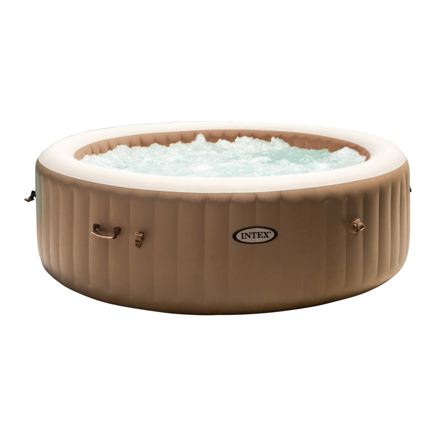
Pure Spa
Characteristic Feature
Control base #:
(new) hexagon type
Power button on the panel
Round & Octagon type
Start from 2020-6-15
Introduction
IMPORTANT
Model #:
12836
SB-H20;SB-H20N
Advertisement
Table of Contents

Related Manuals for Intex PureSpa SB-H20


Summary of Contents for Intex PureSpa SB-H20
- Page 1 Pure Spa 2021SSN BUBBLE Spa Control Base Repair Guide Characteristic Feature Model #: Item # 28426/28428/28476 12836 Control base #: SB-H20;SB-H20N Panel Digital Cable (new) hexagon type Control Panel Power button on the panel Tub shape Round & Octagon type Production date Start from 2020-6-15 Introduction...
- Page 2 28426 Internal Part Page 2...
- Page 3 28426 Internal Part REF. DESC 12840 SPA CONTROL PANEL FOR 28425/28426 12913 BUBBLE SPA CONTROL BASE BACK COVER-KHAKI 12770W CONTROL BASE SIDE COVER 12846 PTC HEATER FOR 28442 12848 AIR BLOWER FOR 28442 12836 SPA CONTROL BASE FOR 28426/28428/28476 11998 SPA RCD 12914 AIR PIPE SET DOWNWARD FOR BUBBLE SPA-KHAKI...
-
Page 4: Table Of Contents
Table of Contents PCB Schematic ---- 5 ---- Basic Tool ---- Understanding a Multimeter ---- Basic Spa Components Control Base Repair ---- Schematics ---- Opening the Control Base ---- Accessing to PCB ---- Internal Parts 13-15 ---- Display Errors Code E90 – No water flow ---- ---- Flow Sensor... -
Page 5: Pcb Schematic
PCB Schematic Remark: From 2020-11-03, Rectifier bridge built in Main circuit board#13052, terminal block E&F change to Q&R. The PCB layout has been totally different with before. Page 5... -
Page 6: Basic Tool
Basic Tools This is a list of basic tools required to repair almost any problem encountered with a control base. Tools such as a digital multimeter and clip-on ammeter are used to test the electrical current of various components on the control base. Psophometers are used to test certain components based on the loudness of the sound they produce. -
Page 7: Understanding A Multimeter
Understanding a Multi-Meter The range with a V and a wavy line measures AC voltage The range with a V and a straight line measures DC voltage First determine whether you will be testing for AC or DC voltage based on this guide and adjust the meter to a range above the expected reading. -
Page 8: Basic Spa Components
Basic Spa Components Control Base - This part houses the heater, water pump, and an air pump. Control Panel- The Control Panel has a display used to adjust temperature and provide diagnostic information when there are problems with the Control Base Spa Tub- Holds the water. - Page 9 Model # SB-H20: Code (SB)n1-(H)n2(20)n3 SB = Spa Bubble H = With Hard Water features 20 = 220-240V working wattage Page 9...
- Page 10 Wiring Schematic Main circuit Board Page 10...
-
Page 11: Opening The Control Base
Opening the Control Base Begin by removing 6 screws around the enclosure. Then take strength to pull out the connector. Open the deflation outlet cap with the included bolt wrench and unscrew the one screw that link the outlet cap to release it from the wire. -
Page 12: Accessing To Pcb
The Control Panel connector is attached to the outer casing, lift the cover vertically carefully to ensure the cable is not pulled and connection between base and cover is not damaged. Accessing the PCB Remove the 2 screws that secure the white PCB cover to reveal the PCB. Unscrew the 2 screws on the holder to remove the PCB set from the Control Base. -
Page 13: Internal Parts
Internal Parts : The terminal has been changed from Nov.03-2020, the indicate mark is Q, R, C, D Page 13... -
Page 14: Pcb
ITEM Part # Transformer 12919 Air Blower 12848 PCB (Main Circuit Board) 13052 Base 12917 20-40℃ Temperature Sensor 12025 Heating Element 12846 Flow sensor 12310 84℃ Temperature Sensor 12029 50℃ Temperature Sensor 12026 Internal Parts Page 14... -
Page 15: Water Pump
Part # ITEM Water Inlet for Tub 12601 Water Outlet for Tub 12915 Air Inlet nut 12914 Electrical Cord with RCD 11998 Water Pump (Filter) 12778 Internal Parts Main circuit Board Black:"50C 黑" - Water Temperature Sensor White:"20~40C 白" - Water Temperature Green: "FLOW 绿"... -
Page 16: Transformer
Error Code E90 This code indicates low water pressure which could be due to an obstruction or a problem with an internal component. Ensure the correct connection between the control base and tub. The tub is filled with water to the recommended level. - Page 17 Error Code E90 (Flow Sensor) 1. Check the connection of the flow sensor. Make sure connectors are in good contact. Ensure that the pins inside the connector are not broken or bent. Color and style of connector may be different from the one shown in the photo below.
- Page 18 Error Code E90 (Water Pump) If the display indicates Code 90 & there is no water flow; 1. If only a click can be heard from the pump when attempting to turn on the unit, there is likely a problem with the water pump. Check the water pump for any broken parts inside. a.
- Page 19 e. Carefully drop the impeller into the pump and ceramic shaft. The magnetism from the impeller is strong so take care not to position your fingers between the impeller and the pump. Add a washer on the ceramic shaft and a rubber cap over the washer. f.
- Page 20 iv. Once the transformer has been exposed, remove 2 screws holding down the cover on the transformer. Take off the cover to expose the transformer. At the picture below, all parts taken from the jet spa are laid out for reference. v.
- Page 21 Error Code E94 This code indicates very low water temperature which could be due frigid water or a problem with the 20-40 C water temperature sensors. Please follow the logic diagram and instructions as below: Display E94 1. Add warn water if water temp. <4℃ 2.
- Page 22 Run the filtering function for 1 minute. If the spa display does not indicate an error code and the unit is circulating water without issue, no further troubleshooting is necessary. Remove the unit for further testing if Error Code 94 is confirmed. a.
- Page 23 Error Code E95 This code indicates very high water temperature which could be hot water or a problem with the 50 ℃ water temperature sensor. Display E95 1. Add cold water if water temp. >50℃ 2. Replace 50C temperature sensor 3.
- Page 24 Error Code E97 This code indicates dry--fire protection which could be due hot water or a problem with the 84C thermal fuse. Display E97 1. Remove cartridge and run heat system. 2. Replace 84C temperature fuse 3. Or replace a PCB Run heat 1 min., E97? Go Back to Next Step...
- Page 25 Error Code E99/ 100℃/ 000℃ This code indicates a bad 20-40 ℃ water temperature sensor. Run the filtering function for 1 minute. If the spa display does not indicate an error code and the unit is circulating water without issue, no further troubleshooting is necessary. Display E99/100/000/212 1.
-
Page 26: End/ Heating Problems
END/ Heating problems This code indicates if after 72 hours of continuous heating operation, the system will hibernate automatically. The defect reason could be heater or a problem with PCB. Display END Run heat 5 min., heater current 4~6A each one? 1. - Page 27 3) If no current was read from terminals (9&10) and (11&12), proceed to change the PCB. Page 27...
- Page 28 Black blank A blank reading on a spa Control Panel indicates components such as RCD failure, PCB failure or a connection issue between the Panel & Base. Plug in and Reset RCD Reconnect Signal Line Panel Blank? Replace a control panel, run system Panel Blank? 1.
-
Page 29: Random Display Or 888
Random Display or 888 If the display is showing random numbers or all the LEDs are lit up, it is possible that there is a connection problem. Random Display/ Code 888 1. Replace Control Panel 2. Replace PCB Random Code? Go Back to Next Step In addition, disconnect and reconnect the cable for the Control Panel. -
Page 30: Air Blower Problem
Air Blower Problems Issues with the air can be due to a defective air pump, bad tub, and damaged or missing seals. Problems with the air pump could also be due to it becoming overheated. No Bubble Run Bubble, bubble come out? 1. - Page 31 If the air blower is too noisy: First check the sound the air blower is making with a psophometer. The Control Base should not be attached to a Tub. Run the air blower function and check for the noise level using the psophometer. If the noise is less than 90 decibels, there is no problem with the air blower.
-
Page 32: How To Replace Rcd
How to Replace RCD 1. Plug the in the Control Base and test the RCD “TEST” and “RESET” functions. In the event the RCD fails, replace the RCD. 2. Change the Control Panel with a new one. Check terminals (1&2) for wall voltage. If there is no voltage, check the electrical outlet and RCD. - Page 33 How to replace PCB 1. Refer to the instruction of Opening the Control Base to remove the screws and open the cover. 2. Remove the 2 screws that secure the white PCB cover to reveal the PCB. Once PCB internal layout is appearing.
- Page 34 How to replace the broken base of spa control 4. Refer to the instruction of Opening the Control Base to remove the screws. 5. Turn over the whole control base and remove the base. Page 34...
Need help?
Do you have a question about the PureSpa SB-H20 and is the answer not in the manual?
Questions and answers