
Related Manuals for ADCMT 6240B


Summary of Contents for ADCMT 6240B
- Page 1 Cover 6240B DC Voltage Current Source/Monitor Operation Manual FOE-00000115B00 MANUAL NUMBER First printing April 23, 2015 ADC CORPORATION 2015 All rights reserved. Printed in Japan...
- Page 3 Safety Summary Safety Summary To ensure thorough understanding of all functions and to ensure efficient use of this instrument, please read the manual carefully before using. Note that ADC Corporation (hereafter referred to as ADC) bears absolutely no re- sponsibility for the result of operations caused due to incorrect or inappropriate use of this instrument. If the equipment is used in a manner not specified by ADC, the protection provided by the equipment may be im- paired.
- Page 4 Safety Summary • Do not place anything on the product and do not apply excessive pressure to the product. Al- so, do not place flower pots or other containers containing liquid such as chemicals near this product. • When the product has ventilation outlets, do not stick or drop metal or easily flammable ob- jects into the ventilation outlets.
- Page 5 Safety Summary Main Parts with Limited Life Part name Life Unit power supply 5 years Fan motor 5 years Electrolytic capacitor 5 years LCD display 6 years LCD backlight 2.5 years Memory backup battery 5 years • Hard Disk Mounted Products The operational warnings are listed below.
- Page 6 Environmental Conditions This instrument should be only be used in an indoor area which satisfies the following conditions: • An area free from corrosive gas • An area away from direct sunlight • A dust-free area • An area free from vibrations •...
- Page 7 Types of Power Cable Replace any references to the power cable type, according to the following table, with the appropriate power cable type for your country. Rating, color Model number Plug configuration Standards and length (Option number) PSE: Japan 125 V at 7 A Straight: A01402 Black...
-
Page 11: Table Of Contents
TABLE OF CONTENTS 6240B DC Voltage Current Source/Monitor Operation Manual TABLE OF CONTENTS PREFACE ...................... Product Overview ....................Supplied Accessories ..................Optional Accessories ..................Operating Environment ..................1.4.1 Environmental Conditions ................1.4.2 Power Specification ..................1.4.3 Changing Power Voltage, and Checking or Replacing Power Fuse .. - Page 12 6240B DC Voltage Current Source/Monitor Operation Manual Table of Contents 2.2.5 DC Measurement ..................2-34 2.2.6 Pulse Measurement ..................2-38 2.2.7 Sweep Measurement ................... 2-42 2.2.8 Random Sweep Source ................2-47 2.2.9 Low-Resistance Measurement ..............2-52 Saving and Loading Parameters ................
- Page 13 6240B DC Voltage Current Source/Monitor Operation Manual Table of Contents 5.2.3.1 Operations in DC Sweep Source Mode ............5-15 5.2.3.2 Operations in Pulse Sweep Source Mode ........... 5-17 5.2.3.3 Random Sweep and Random Pulse Sweep ..........5-18 5.2.3.4 2-Slope Linear Sweep .................
- Page 14 6240B DC Voltage Current Source/Monitor Operation Manual Table of Contents 5.4.1 Block Diagram .................... 5-75 5.4.2 Operational Principles ................5-75 REMOTE PROGRAMMING ..............Using Interface ....................6.1.1 Selecting Interface ..................Remote Command Index ................... GPIB ........................6.3.1 Overview ....................6.3.2 Precautions when Using GPIB ..............
- Page 15 6240B DC Voltage Current Source/Monitor Operation Manual Table of Contents SPECIFICATIONS ..................Source and Measurement .................. Source and Measurement Function ..............Setting Time ...................... 9-10 General Specifications ..................9-12 Supplementary Descriptions ................9-13 9.5.1 How to Calculate Accuracy for Current Source, Current Measurement and Current Limiter ..........
- Page 17 6240B DC Voltage Current Source/Monitor Operation Manual LIST OF ILLUSTRATIONS Title Page Voltage and Current Output Range .................. Operating Environment ..................... Setting Power Voltage Indicator ..................Power Cable ........................Connecting Power Cable ....................1-10 Self-Test in Progress ......................1-10 Self Test Completion ......................
- Page 18 6240B DC Voltage Current Source/Monitor Operation Manual List of Illustrations Title Page Reducing Stray Capacitance and Lead Inductor ............... Preventing DUT Oscillation ..................... Preventing 6240B Oscillation ................... Connection for High Current Measurement ..............Connection with 12701A ....................Random Sweep and Random Pulse Sweep ...............
- Page 19 6240B DC Voltage Current Source/Monitor Operation Manual LIST OF TABLES Title Page Standard Accessory List ....................Optional Accessory List ....................Power Supply Specification ....................Menu and Key Functions ....................2-26 Tolerable Current and Wire Thickness ................Operations in DC Source Mode ..................
-
Page 21: Preface
This chapter describes the accessories, operating environment, precautions, and operating check for person- nel who operate the 6240B. Read this manual before using the 6240B. Product Overview The 6240B is a DC Voltage Current Source/Monitor that offers high sensitivity with 4 digit source resolu- tion and 5 digit measurement resolution, as well as various sweep functions and a pulse measurement func- tion with a minimum pulse width of 50 s. -
Page 22: Voltage And Current Output Range
6240B DC Voltage Current Source/Monitor Operation Manual 1.1 Product Overview Current Voltage DC, Pulse Pulse (with conditions) For the conditions of pulse output, refer to Section 5.2.5.3, "Restrictions on Output Range." Pulse source value Base value Tw: Pulse width Pulse period... -
Page 23: Supplied Accessories
6240B DC Voltage Current Source/Monitor Operation Manual 1.2 Supplied Accessories Supplied Accessories The 6240B standard accessories are listed below. If any accessory is missing or damaged, contact an ADC CORPORATION sales representative. Specify the part number when ordering. Table 1-1 Standard Accessory List... -
Page 24: Optional Accessories
6240B DC Voltage Current Source/Monitor Operation Manual 1.3 Optional Accessories Optional Accessories The 6240B optional accessories are listed below. Specify the part number when ordering. Table 1-2 Optional Accessory List Name Part number Remarks Test fixture 12701A Connecting cable A01041... -
Page 25: Operating Environment
Obstructing the vents will cause the internal temperature to rise, possibly causing faulty operation. • Mounting in a rack Ensure that exhaust air from other devices is not directed at the vents on the side of the 6240B. To prevent the temperature in the rack from rising, install a heat sink fan. -
Page 26: Operating Environment
• Keep the rear panel more than 10 centimeters away the rear panel facing down. from the wall Figure 1-2 Operating Environment NOTE: Warm-up Time Allow the 6240B to warm up for at least 60 minutes after turning on the power to ensure the specified accuracy of the 6240B. -
Page 27: Power Specification
1.4.2 Power Specification 1.4.2 Power Specification Table 1-3 below shows the 6240B power supply specifications. CAUTION: To prevent damage to the 6240B, do not apply a voltage or frequency that exceeds the specified range. Table 1-3 Power Supply Specification Optional Standard... -
Page 28: Changing Power Voltage, And Checking Or Replacing Power Fuse
1.4.3 Changing Power Voltage, and Checking or Replacing Power Fuse 1.4.3 Changing Power Voltage, and Checking or Replacing Power Fuse The 6240B power voltage can be changed manually. This section describes the procedure for changing the power voltage, and checking and replacing the power fuse. -
Page 29: Power Cable
6240B DC Voltage Current Source/Monitor Operation Manual 1.4.4 Power Cable 1.4.4 Power Cable CAUTION: Use a power cable that conforms to the power outlet voltage and type. However, for use outside of Japan, use only a power cable approved for the respective country. -
Page 30: Operating Check
1.5 Operating Check Operating Check This section describes the simple self-test which must be performed when operating the 6240B for the first time. Follow the procedure below to ensure the instrument operates correctly. Ensure that the POWER switch on the front panel is set to OFF. -
Page 31: Self Test Completion
6240B DC Voltage Current Source/Monitor Operation Manual 1.5 Operating Check Software revision Figure 1-7 Self Test Completion Figure 1-8 Start-Up Screen NOTE: Depending on the previous conditions, the screen display may be different from Figure 1-8. If a problem occurs, an error message appears on the screen. -
Page 32: Vsvm 0 V Measurement In 300 Mv Range
Verify that the VM measured value is within 150 V of 0 V in the VS 300 mV range. Press STBY. The OPR indicator goes OFF and the 6240B enters the Standby (output OFF) sta- tus. The operation check is complete. -
Page 33: Cleaning, Storage, And Transport Methods
Storage Store the 6240B in a location where the temperature is within the range of -25º C to +70 ºC. If storing for an extended period (90 days or longer), place the 6240B in a moisture-proof bag together with a desiccant. -
Page 34: Warm-Up Time
6240B DC Voltage Current Source/Monitor Operation Manual 1.7 Warm-up Time Warm-up Time Allow the 6240B to warm up for at least 60 minutes after turning on the power to ensure the specified accu- racy of the 6240B. Calibration Calibrate the 6240B in accordance with the procedure described in Chapter 8. "CALIBRATION."... -
Page 35: 1.10 Product Disposal And Recycling
1.10 Product Disposal and Recycling 1.10 Product Disposal and Recycling Correctly dispose of the 6240B in accordance with local and national regulations. Before disposal, remove the following parts from the product to prevent dispersal of substances that may adversely affect the environment, human health, or the ecosystem. - Page 36 6240B DC Voltage Current Source/Monitor Operation Manual 1.10 Product Disposal and Recycling Name of substance or removed part Used? Location Unit Part Nickel or its compounds Unit Electronic components, mechanical components Lead or its compounds Unit BPL-034287X04 Lead solder used for...
-
Page 37: Operation
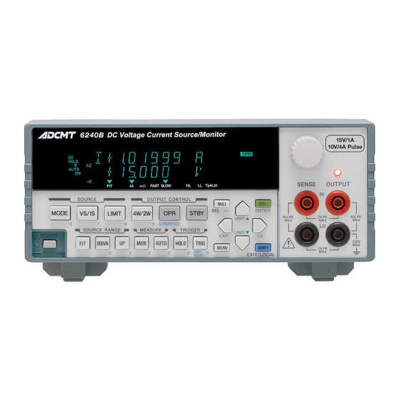
6240B DC Voltage Current Source/Monitor Operation Manual 2. OPERATION OPERATION This chapter describes the part names and functions on the front and rear panels and screen display (annota- tions) elements. The basic operations are explained by using measurement examples. Panel Description This section describes the part names and functions on the front and rear panels and the screen display (anno- tation) elements. -
Page 38: Display Section
6240B DC Voltage Current Source/Monitor Operation Manual 2.1.1 Front Panel 2.1.1.1 Display Section Figure 2-2 Display Section Display The screen employs a vacuum fluorescent display. It displays the source value, the measurement value and the unit operational status. It functions as setting screen when changing the setting parame- ters. -
Page 39: Source Range Section
6240B DC Voltage Current Source/Monitor Operation Manual 2.1.1 Front Panel 2.1.1.3 SOURCE RANGE Section Figure 2-4 SOURCE RANGE Section FIT key Selects the optimum fitting range (FIT) or the currently setting range to input the source values. DOWN key Lowers the source range. -
Page 40: Output Control Section
6240B DC Voltage Current Source/Monitor Operation Manual 2.1.1 Front Panel 2.1.1.5 OUTPUT CONTROL Section 2, 3 Figure 2-6 OUTPUT CONTROL Section 4W/2W key Selects the output sensing 4-wire or 2-wire connection. OPR key Switches between Operate and Suspend*. * : Suspend status outputs the suspended voltage without turning OFF the output relays. -
Page 41: Other Keys
6240B DC Voltage Current Source/Monitor Operation Manual 2.1.1 Front Panel 2.1.1.7 Other Keys 7, 8, 9 Figure 2-8 Other Keys MENU key Displays a parameter group setting (menu) screen. NULL key Turns ON or OFF the NULL calculation. 123... key Switches to the direct input mode which accepts the numerical input and sets input values. -
Page 42: Output Section
6240B DC Voltage Current Source/Monitor Operation Manual 2.1.1 Front Panel 2.1.1.8 Output Section Figure 2-9 Output Section OUTPUT terminals Voltage and current output terminals SENSE terminals Function as sensing terminals for voltage output and input termi- nals for voltage measurement in the remote sense mode (4-wire connection). -
Page 43: Screen Display (Annotations)
6240B DC Voltage Current Source/Monitor Operation Manual 2.1.2 Screen Display (Annotations) 2.1.2 Screen Display (Annotations) This section describes the screen display (annotations). Figure 2-11 Screen Display (Annotations) Source value Displays a voltage source (VS) or current source (IS) value with a unit. - Page 44 6240B DC Voltage Current Source/Monitor Operation Manual 2.1.2 Screen Display (Annotations) Left status indicators PLS: Pulse source mode or low-resistance measurement pulse source mode SWP: Sweep source mode NOTE: PLS+SWP means pulse sweep, and DC+SW means DC sweep. DC source mode.
- Page 45 6240B DC Voltage Current Source/Monitor Operation Manual 2.1.2 Screen Display (Annotations) 11. Right status indicators RMT : Remote control Addressed as Lister or Talker via GPIB SRQ: SRQ is being transmitted. MAX, MIN, AVE, : MAX/MIN calculation is ON. :...
- Page 46 2.1.3 Rear Panel Figure 2-12 Rear Panel AC power connector Connects the 6240B to the AC power supply by using the supplied power cable. Voltage selector and fuse holder Selects voltage manually to match the AC power supply. A fuse is contained inside.
- Page 47 6240B DC Voltage Current Source/Monitor Operation Manual 2.1.3 Rear Panel INTERLOCK|OPERATE IN/OUT INTERLOCK : Interlock signal input The input resistance is approximately 10 k. OPERATE IN : Sets Standby by a rising edge signal input in the STBY In function.
-
Page 48: Basic Operation
6240B DC Voltage Current Source/Monitor Operation Manual 2.2 Basic Operation Basic Operation This section describes the following items: • Setting the source value • Setting the limit values • How to use the menu and basic measurement functions NOTE: The operation procedures listed permit the settings to be made in the shortest time. If the display differs from the one shown, repeat the procedure from the beginning. -
Page 49: Setting Source Value Using Cursor Keys/Rotary Knob
6240B DC Voltage Current Source/Monitor Operation Manual 2.2.1 Setting Source Value 2.2.1.2 Setting Source Value Using Cursor Keys/Rotary Knob (with FIT Indicator OFF) Change the source value using the cursor keys ( ) and the UP/DOWN keys ( ) or the rotary knob ( keys move the cursor (blinking) position left and right. - Page 50 6240B DC Voltage Current Source/Monitor Operation Manual 2.2.1 Setting Source Value Press or rotate one click counterclockwise. The figure indicated by the cursor decreases by one increment. Cursor (blinking) Keep pressing The figure indicated by the cursor increases incrementally while the key is being pressed.
- Page 51 6240B DC Voltage Current Source/Monitor Operation Manual 2.2.1 Setting Source Value Changing the source range Change the source range by using the DOWN or UP key. • The range change adjusts to synchronize the source value before and after the change.
- Page 52 6240B DC Voltage Current Source/Monitor Operation Manual 2.2.1 Setting Source Value • When changing 1A range to 4 A range, the smallest digit is rounded off to an even number. (1 A range) (4 A range) • If the final value would exceed the valid range, change is not possible.
-
Page 53: Setting Source Value Using Cursor Keys/Rotary Knob
6240B DC Voltage Current Source/Monitor Operation Manual 2.2.1 Setting Source Value 2.2.1.3 Setting Source Value Using Cursor Keys/Rotary Knob (with FIT Indicator When the FIT indicator turns ON, the range is automatically adjusted so that the source value is generated in the optimum range. -
Page 54: Setting Source Value Using Direct Input Mode
6240B DC Voltage Current Source/Monitor Operation Manual 2.2.1 Setting Source Value Press or rotate one click counterclockwise. The source range is automatically set to 3 V. Cursor (blinking) 2.2.1.4 Setting Source Value Using Direct Input Mode Press 123... key to turn to the direct input mode, and set the source value by using the numeric keys and the unit key which are printed in green on the panel. - Page 55 6240B DC Voltage Current Source/Monitor Operation Manual 2.2.1 Setting Source Value Press 3, ., and 1 in this order. While inputting figures, the cursor blinks. Blinking Press ENTER. The numeric value has been applied and the direct input mode is released.
-
Page 56: Setting Limit Values
6240B DC Voltage Current Source/Monitor Operation Manual 2.2.2 Setting Limit Values 2.2.2 Setting Limit Values Press LIMIT to set the limit value setting screen. To change the limit values, follow the procedure described in Section 2.2.1, "Setting Source Value." How- ever, the range cannot be set. - Page 57 6240B DC Voltage Current Source/Monitor Operation Manual 2.2.2 Setting Limit Values Press or rotate one click clockwise. The range increases by one, and the LL value also changes at the same time. The LL value cannot be changed directly. Separate setting Press LIMIT.
- Page 58 6240B DC Voltage Current Source/Monitor Operation Manual 2.2.2 Setting Limit Values Press NULL (SEL). The cursor moves to the LL value, and the HL value is displayed at half-bright- ness. Half-brightness Cursor (blinking) Move the cursor to 3. Half-brightness Cursor (blinking)
- Page 59 6240B DC Voltage Current Source/Monitor Operation Manual 2.2.2 Setting Limit Values Press LIMIT to display the limit value setting screen. Cursor (blinking) Half-brightness Press NULL (SEL) to select LL and move the cursor to 3. Half-brightness Cursor (blinking) Press twice, and press once.
-
Page 60: 2.2.3 Menu Operation
6240B DC Voltage Current Source/Monitor Operation Manual 2.2.3 Menu Operation 2.2.3 Menu Operation The 6240B functions and parameters are set on a hierarchical menu. The menu is a 3-level hierarchical structure. Level 1 Category level Select a category. Level 2 Select level Select a parameter to set within the category. -
Page 61: Menu Operation Overview
6240B DC Voltage Current Source/Monitor Operation Manual 2.2.3 Menu Operation HOME screen Level 1 Category level Level 2 Select level Level 3 Input/Run level Cursor flashes Select parameter on numeric blinks parameter Direct input Unit Numeric value *1 Enter a parameter to return to the normal screen. -
Page 62: Menu And Key Functions
6240B DC Voltage Current Source/Monitor Operation Manual 2.2.3 Menu Operation Table 2-1 Menu and Key Functions Input/Run level Category level Select level Numeric Select parameter parameter Go to Category Go to Select level Go to Select level Go to Select level... -
Page 63: Menu Structure And Parameter Setting
6240B DC Voltage Current Source/Monitor Operation Manual 2.2.3 Menu Operation 2.2.3.2 Menu Structure and Parameter Setting Category level Select level Input/Run level Parameter type MENU A) SOURCE 1) PLS Base Pulse source base value Numeric VS +000.00 mV to 15.000 V +00.000 mA to 1.0000 A... - Page 64 6240B DC Voltage Current Source/Monitor Operation Manual 2.2.3 Menu Operation Category level Select level Input/Run level Parameter type C) SWEEP VAL 1) Start Value Numeric Linear sweep start value In Linear mode VS +000.00 mV to 15.000 V +00.000 A to 4.0000 A...
- Page 65 6240B DC Voltage Current Source/Monitor Operation Manual 2.2.3 Menu Operation Category level Select level Input/Run level Parameter type D) TIME 1) Hold Time Hold time Numeric 1 ms to 60 s 2) Src Delay Source delay time Numeric 30 s to 59.998 s...
- Page 66 6240B DC Voltage Current Source/Monitor Operation Manual 2.2.3 Menu Operation Category level Select level Input/Run level Parameter type G) RANDOM MEM 1) Data Set .. Random memory setting Numeric * Press [SEL] to switch between address and data input. 2) Save/Clear Random memory clear (RAM)/ Random memory save (RAM ...
- Page 67 6240B DC Voltage Current Source/Monitor Operation Manual 2.2.3 Menu Operation Category level Select level Input/Run level Parameter type J) EXT SIGNAL 1) OPR Signal INTERLOCK/OPERATE IN/OUT control signal function Select setting STBY In / IntrLock In / Operate Out / OPR/SUS In...
- Page 68 6240B DC Voltage Current Source/Monitor Operation Manual 2.2.3 Menu Operation Category level Select level Input/Run level Parameter type M) SYSTEM 1) Limit Buz Limiter detection buzzer Select Off / On 2) Compare Buz Comparator calculation result buzzer Select Off / HI / GO / LO / HI or LO...
-
Page 69: Initializing Setting Conditions
6240B DC Voltage Current Source/Monitor Operation Manual 2.2.4 Initializing Setting Conditions 2.2.4 Initializing Setting Conditions The following procedure initializes the 6240B to the factory default settings. However, the following items are not initialized. • Selected interface • GPIB address •... -
Page 70: 2.2.5 Dc Measurement
-3 mA (c) Operating Point Figure 2-15 DC Measurement Preparation Initialize the 6240B in accordance with the procedure described in Section 2.2.4, "Initializing Setting Conditions." Connect the DUT with the supplied input and output cables and alligator clips. • Connect the A08532 alligator clips to the A01044 input and output cables. - Page 71 The following example operation uses ideal values, assuming that the 1 k resistor, the cables, the 6240B and other properties have no errors in both source and measurement. In the actual operation, some error factors do exist and the measured values will be different from the example.
- Page 72 6240B DC Voltage Current Source/Monitor Operation Manual 2.2.5 DC Measurement Voltage source (VSIM) Press OPR. The OPR indicator goes ON showing the Operate status (output ON). The mea- sured current value is displayed when 1 V is applied to the 1 k resistor. (See Point A in Figure 2-15).
- Page 73 As the source current is limited by the current limiter, the limiter indicator goes ON. (See Point D in Figure 2-15.) Current source (ISVM) 11. Press VS/IS. The measurement changes to current source and the 6240B goes into Suspend status. Blinking Cursor (blinking) 12.
-
Page 74: 2.2.6 Pulse Measurement
6240B DC Voltage Current Source/Monitor Operation Manual 2.2.6 Pulse Measurement 13. Press MON twice to switch to voltage measurement. (See Point B in Figure 2-15.) Cursor (blinking) 2.2.6 Pulse Measurement This section describes an example operation which uses the pulse source mode. - Page 75 6240B DC Voltage Current Source/Monitor Operation Manual 2.2.6 Pulse Measurement Preparation Follow the same procedure described in Section 2.2.5, "DC Measurement." Setting the pulse source value Press 123…, 2, UNIT , and ENTER in order. The pulse source value is set to 2 V.
- Page 76 6240B DC Voltage Current Source/Monitor Operation Manual 2.2.6 Pulse Measurement 11. Press tto select 3) Meas Delay. Press to enter the Input/Run level. 12. Press 123..., 3 and ENTER in order. Tdl is set to 3 ms. 13. Press to select 4) Pls Width. Press to enter the Input/Run level.
- Page 77 6240B DC Voltage Current Source/Monitor Operation Manual 2.2.6 Pulse Measurement 22. Press to change the source value (pulse value) to 2.5 V. The measured current value with the pulse value of 2.5 V is displayed. Cursor (blinking) Current measurement with the base value 23.
-
Page 78: Sweep Measurement
6240B DC Voltage Current Source/Monitor Operation Manual 2.2.7 Sweep Measurement 2.2.7 Sweep Measurement This section describes how to read out measurement data from the memory by using the sweep source mode. In voltage source current measurement (VSIM), linear sweep is performed with steps of 0.5 V from 0.5 V to 5 V as shown in Figure 2-17 below. - Page 79 6240B DC Voltage Current Source/Monitor Operation Manual 2.2.7 Sweep Measurement Preparation Follow the same procedure described in Section 2.2.5, "DC Measurement." Setting the current limit value Press 123…, 3, 0, UNIT and ENTER in order. The current limit value is set to ±30 mA.
- Page 80 6240B DC Voltage Current Source/Monitor Operation Manual 2.2.7 Sweep Measurement 11. Press 123…, 5, UNIT and ENTER in order. The stop value is set to 5 V. 12. Press to select 3) Step Value. Press to enter the Input/Run level.
- Page 81 6240B DC Voltage Current Source/Monitor Operation Manual 2.2.7 Sweep Measurement 26. Press MENU. The HOME screen is displayed. 27. Confirm that the ST indicator goes ON. Starting sweep measurement 28. Press OPR. The Operate status is set. The source value indicates the bias value.
- Page 82 6240B DC Voltage Current Source/Monitor Operation Manual 2.2.7 Sweep Measurement 33. Press to select 2) Mem Recall. Press to enter the Input/Run level. The data stored in the measurement data memory is read out. The final stored data is displayed.
-
Page 83: Random Sweep Source
6240B DC Voltage Current Source/Monitor Operation Manual 2.2.8 Random Sweep Source 2.2.8 Random Sweep Source This section describes an example of random sweep from 1 V to 3 V as shown below. Turning off measurement enables high-speed sweep. Press TRIG... - Page 84 6240B DC Voltage Current Source/Monitor Operation Manual 2.2.8 Random Sweep Source Preparation Initialize the 6240B following the same procedure described in Section 2.2.5, "DC Measurement." Setting the sweep source mode Press MODE. Rotate or press to select DC-SWP, and press ENTER.
- Page 85 6240B DC Voltage Current Source/Monitor Operation Manual 2.2.8 Random Sweep Source 11. Press 123..., 2, and ENTER in order. The stop address is set to 2. Setting the time 12. Press in order to select D) TIME. 13. Press to select 1) Hold Time. Press to enter the Input/Run level.
- Page 86 6240B DC Voltage Current Source/Monitor Operation Manual 2.2.8 Random Sweep Source 18. Press 123..., 2, and ENTER in order. The period time is set to 2 ms. Setting measurement to OFF 19. Press in order to select E) MEASURE. 20. Press in order to select 3) Measure SW.
- Page 87 6240B DC Voltage Current Source/Monitor Operation Manual 2.2.8 Random Sweep Source Starting random sweep 28. Press OPR. The Operate status is set. The source value indicates the bias value. 29. Press TRIG. Random sweep starts while displaying the source value. When the sweep is com- plete, the initial screen is returned.
- Page 88 4 wire Figure 2-19 Low-Resistance Measurement Preparation Initialize the 6240B following the same procedure described in Section 2.2.5, "DC Measurement." Connect the DUT in 4 wires with the supplied input and output cables and alli- gator clips. For more information on the 4-wire connection, refer to Section 5.1.2, "Remote Sensing (2-Wire/4-Wire Connection)."...
- Page 89 6240B DC Voltage Current Source/Monitor Operation Manual 2.2.9 Low-Resistance Measurement Setting the low-resistance measurement pulse source mode Press MODE. Rotate or press to select PLS-RM, and press ENTER. The PLS indicator and the m indicator go ON, showing the low-resistance measurement pulse source mode has been set.
- Page 90 6240B DC Voltage Current Source/Monitor Operation Manual 2.2.9 Low-Resistance Measurement 12. Press to select 4) Pls Width. Press to enter the Input/Run level. 13. Press 123..., 2, 0 and ENTER in order. The pulse width is set to 20 ms.
-
Page 91: Saving And Loading Parameters
2.3.1 Auto Load at Power ON When the 6240B is turned on, it starts up with the setting parameters from when it was previously turned off. However, the 6240B also starts up with the same condition by loading the parameters saved in Area 0. -
Page 92: 2.3.2 Saving Parameters
6240B DC Voltage Current Source/Monitor Operation Manual 2.3.2 Saving Parameters 2.3.2 Saving Parameters Operation Character display area Press MENU and select K) PARAMETER with K) PARAMETER 1) Parm Load Enter the Select level with Load0 2) Parm Save Select 2) Parm Save with... -
Page 93: Measurement Example
6240B DC Voltage Current Source/Monitor Operation Manual 3. MEASUREMENT EXAMPLE MEASUREMENT EXAMPLE This chapter describes the application examples of the 6240. Diode Measurement This section describes an example of measuring diode forward voltage (VF) using pulse current. NOTE: Use 4-wire connection for accurate measurement of the forward voltage. -
Page 94: Diode Measurement Connection
6240B DC Voltage Current Source/Monitor Operation Manual 3.1 Diode Measurement Connecting the DUT Connect the A08532 alligator clips to the supplied A01044 input and output cables and connect the diode as shown below. 2-wire connection is used in this measurement example. -
Page 95: Battery Charge And Discharge Test
The charge and discharge test takes a long time and should be executed by a system via remote control. How- ever, a manual operation example is described here to show how to use the functions of the 6240B. The battery is charged with DC constant current and voltage, and is stopped charging when the charge current reaches the specified current or below. -
Page 96: Battery Charge Discharge Test Connection
6240B DC Voltage Current Source/Monitor Operation Manual 3.2 Battery Charge and Discharge Test Connecting the DUT Use 4-wire connection as shown below so that the cables do not cause a voltage drop. Connect the COMPLETE OUT terminal with the OPERATE IN terminal on the rear panel by using the BNC-BNC cables A01036. - Page 97 6240B DC Voltage Current Source/Monitor Operation Manual 3.2 Battery Charge and Discharge Test Test conditions are described below. Charge test: Charge with a constant current of 500 mA. After the voltage reaches 1.45 V, charge with a constant voltage. When the current reaches 100 mA or below, stop charging.
-
Page 98: Battery Discharge Test Waveforms
6240B DC Voltage Current Source/Monitor Operation Manual 3.2 Battery Charge and Discharge Test Discharge test: As shown below, discharge with a constant current of 500 mA, a pulse width of 20 ms and a 1 s period. When the voltage reaches 1.0 V, stop discharging. -
Page 99: Menu Index
6240B DC Voltage Current Source/Monitor Operation Manual 4. REFERENCE REFERENCE This chapter describes panel keys, parameter groups, parameter items and parameter functions in the follow- ing sections. • 4.1 Menu Index: Use this section as an index for the parameters in the menu. - Page 100 6240B DC Voltage Current Source/Monitor Operation Manual 4.1 Menu Index Step1 Val ..........4-7 Step2 Val ..........4-7 Stop Value ..........4-6 Store Mode ..........4-9 Suspend V ..........4-4 Suspend Z ..........4-4 SWEEP ........... 4-5 Sweep Adr ..........4-7 Sweep Type ..........
-
Page 101: Function Description
6240B DC Voltage Current Source/Monitor Operation Manual 4.2 Function Description Function Description This section describes the panel keys and the parameter functions in alphabetical order. 4.2.1 AUTO key (Measurement Range) Switches between measurement auto range and fixed range. Auto range: Measures in the optimum range between the limiter range and the minimum range. -
Page 102: Hold Key (Trigger Mode)
6240B DC Voltage Current Source/Monitor Operation Manual 4.2.4 HOLD Key (Trigger Mode) 4.2.4 HOLD Key (Trigger Mode) Switches the source and measurement trigger mode. Source mode AUTO HOLD DC/Pulse Repeats source and measurement within Executes source and measure- the period time of the time parameter. - Page 103 6240B DC Voltage Current Source/Monitor Operation Manual 4.2.6 MENU Key (Parameter Setting) LMT Input Selects the current limiter HL and LL values setting. Balance : The HL and LL values change simultaneously in both polarities Separate: The HL and LL values are separately set.
-
Page 104: Linear Sweep
6240B DC Voltage Current Source/Monitor Operation Manual 4.2.6 MENU Key (Parameter Setting) Linear: SWEEP VAL Start Value Sets the start value for linear sweep. Stop Value Sets the stop value for linear sweep. Step Value Sets the step value for linear sweep. - Page 105 6240B DC Voltage Current Source/Monitor Operation Manual 4.2.6 MENU Key (Parameter Setting) Random: SWEEP VAL Sweep Adr Sets the start and stop addresses for random sweep. Select the parameter by using the NULL (SEL) key. Bias Value Sets the bias value (source value before sweep start).
- Page 106 6240B DC Voltage Current Source/Monitor Operation Manual 4.2.6 MENU Key (Parameter Setting) Pls Width Sets the pulse width (Tw) in the pulse source mode or pulse sweep mode. Period Sets the following period time (Tp). • Auto sampling period in the DC source mode •...
- Page 107 6240B DC Voltage Current Source/Monitor Operation Manual 4.2.6 MENU Key (Parameter Setting) Measure SW Switches measurement ON or OFF. Executes measurement. Off: Does not execute measurement. Disp Digit Selects the number of measurement display digits. Spaces are displayed as blank digits but do not affect any mea- surement data.
- Page 108 6240B DC Voltage Current Source/Monitor Operation Manual 4.2.6 MENU Key (Parameter Setting) COMPUTE Set the calculation-related parameters. Compare SW Switches the comparator calculation ON or OFF. Executes the comparator calculation. The calculation result is reflected on the indicator, the header of GPIB data output and the status byte.
-
Page 109: Stby In
Operate or Suspend Operate and Suspend are disabled. Figure 4-5 InterLock In Operate Out: Outputs LO when the 6240B is in Operate status, and HI in Standby or Suspended status. Operate Operate Out signal output Standby or Suspend Figure 4-6 Operate Out... - Page 110 6240B DC Voltage Current Source/Monitor Operation Manual 4.2.6 MENU Key (Parameter Setting) OP/STBY In: Sets Standby when the signal level changes from LO to HI. Sets Operate when the signal level changes from HI to LO. OPR/STBY In signal input...
- Page 111 6240B DC Voltage Current Source/Monitor Operation Manual 4.2.6 MENU Key (Parameter Setting) PARAMETER Loads or saves the setting parameters. Parm Load Loads the setting parameters from the non-volatile memory. Not displayed on the menu screen in Operate status. Load0: Loads the data from area 0 of the non-volatile memory as setting parameters.
- Page 112 6240B DC Voltage Current Source/Monitor Operation Manual 4.2.6 MENU Key (Parameter Setting) Header Switches the header ON or OFF. Header ON Off: Header OFF Talk Only Switches between Addressable and Talk Only. NOT displayed when the USB interface is selected.
-
Page 113: Mode Key (Source Mode)
6240B DC Voltage Current Source/Monitor Operation Manual 4.2.7 MODE Key (Source Mode) 4.2.7 MODE Key (Source Mode) Selects the source mode by using Source Mode Switches the source mode. Enabled only in Standby or Suspend status. Sets the DC source mode which generates DC voltage or DC current. -
Page 114: Null/Sel Key
6240B DC Voltage Current Source/Monitor Operation Manual 4.2.9 NULL/SEL Key 4.2.9 NULL/SEL Key NULL key: Switches the NULL calculation ON or OFF. For more information on the NULL calculation function, refer to Section 5.2.10.1, "NULL Calculation." SEL Key: Selects the parameters at the Input/Run level in the menu. -
Page 115: Shift/Local Key (Shift Mode/Local)
6240B DC Voltage Current Source/Monitor Operation Manual 4.2.11 SHIFT/LOCAL Key (Shift Mode/Local) 4.2.11 SHIFT/LOCAL Key (Shift Mode/Local) SHIFT key (in normal operation): Functions as SHIFT key, and the SHIFT indicator goes ON. In the shift status, function names printed in blue characters on the panel are enabled. -
Page 116: Trig/Swp Stop Key (Trigger/Sweep Stop)
6240B DC Voltage Current Source/Monitor Operation Manual 4.2.13 TRIG/SWP STOP Key (Trigger/Sweep Stop) 4.2.13 TRIG/SWP STOP Key (Trigger/Sweep Stop) TRIG key: Functions as source or measurement trigger key. Trigger mode Source mode AUTO HOLD DC source mode/pulse source mode/ Triggers measurement and pulse low-resistance measurement pulse source mode source. -
Page 117: Vs/Is Key (Source Function)
6240B DC Voltage Current Source/Monitor Operation Manual 4.2.15 VS/IS Key (Source Function) 4.2.15 VS/IS Key (Source Function) Selects the source function, voltage source or current source. The unit indicates the present source func- tion. There are the following restrictions on switching between VS and IS: •... -
Page 119: Technical References
This chapter describes the detailed functions for more accurate measurement. DUT Connection 5.1.1 Note for Output Terminals Figure 5-1 below shows the internal wire connection of the 6240B. The output terminals are cut off from the internal circuits by the Operate/Standby relays in Standby status. HI SENSE HI OUTPUT... -
Page 120: Remote Sensing (2-Wire/4-Wire Connection)
5.1.2 Remote Sensing (2-Wire/4-Wire Connection) 5.1.2 Remote Sensing (2-Wire/4-Wire Connection) When connecting the 6240B and the DUT, use 2-wire or 4-wire connection while considering the follow- ing conditions: • Apply 2-wire connection if the output current is relatively low and the cable line resistance does not matter. - Page 121 6240B DC Voltage Current Source/Monitor Operation Manual 5.1.2 Remote Sensing (2-Wire/4-Wire Connection) NOTE: The maximum remote sensing voltage (tolerable voltage difference between OUTPUT and SENSE) is 1 V at both HI and LO sides. To satisfy the specified accuracy, maintain the following restriction for r to r ...
-
Page 122: Preventing Oscillation
5.1.3 Preventing Oscillation 5.1.3 Preventing Oscillation The DUT itself may oscillate, or the 6240B may oscillate if capacitance or inductance exceeding the spec- ified value is connected (due to stray capacitance or retained inductance from connected cables, a scanner, or a fixture). -
Page 123: Preventing Dut Oscillation
6240B DC Voltage Current Source/Monitor Operation Manual 5.1.3 Preventing Oscillation 5.1.3.2 Preventing DUT Oscillation The DUT itself may oscillate due to the stray capacitance of cables and a test fixture. Particularly a high transistor or a high gm FET has a higher probability of oscillation. -
Page 124: Connection For High Current Measurement
6240B DC Voltage Current Source/Monitor Operation Manual 5.1.4 Connection for High Current Measurement 5.1.4 Connection for High Current Measurement Be sure to use 4-wire connection to measure high current. Twist together the cables between HI OUTPUT and LO OUTPUT and between HI SENSE and LO SENSE from the output terminals to the DUT terminals as in Figure 5-6 to avoid overshoot or delay in response because of cable inductance. -
Page 125: Connection With Fixture 12701A
CAUTION:Follow the procedure below to prevent electric shock. Be sure to ground the 12701A protective grounding terminal Connect the 12701A LID SIGNAL to the INTERLOCK terminal on the 6240B rear panel, and set the param- eter "OPR Signal" to InterLock In. -
Page 126: Functions In Detail
6240B DC Voltage Current Source/Monitor Operation Manual 5.2 Functions in Detail Functions in Detail 5.2.1 Operations in DC Source Mode The following table shows operations in the DC source mode. Table 5-2 Operations in DC Source Mode (1/2) Operational Trigger mode... - Page 127 6240B DC Voltage Current Source/Monitor Operation Manual 5.2.1 Operations in DC Source Mode Table 5-2 Operations in DC Source Mode (2/2) Operational Trigger mode Description Operation Remarks condition Source value Tp: Period time changing induces Td: Measurement delay time range changing.
-
Page 128: 5.2.2 Operations In Pulse Source Mode
6240B DC Voltage Current Source/Monitor Operation Manual 5.2.2 Operations in Pulse Source Mode 5.2.2 Operations in Pulse Source Mode The following table shows operations in the pulse source mode. Table 5-3 Operations in Pulse Source Mode (1/2) Operational Trigger mode... - Page 129 6240B DC Voltage Current Source/Monitor Operation Manual 5.2.2 Operations in Pulse Source Mode Table 5-3 Operations in Pulse Source Mode (2/2) Operational Trigger mode Description Operation Remarks condition Source value Tp: Period time changing induces Tw: Pulse width range changing.
-
Page 130: Operations In Sweep Source Mode
6240B DC Voltage Current Source/Monitor Operation Manual 5.2.3 Operations in Sweep Source Mode 5.2.3 Operations in Sweep Source Mode The following table shows operations in the sweep source mode. Table 5-4 Operations in Sweep Source Mode (1/2) Sweep types Description... - Page 131 6240B DC Voltage Current Source/Monitor Operation Manual 5.2.3 Operations in Sweep Source Mode Table 5-4 Operations in Sweep Source Mode (2/2) Sweep types Description Waveform Sweeps with staircase pulse wave- forms of the step value between the Linear sweep first value and the last value.
- Page 132 6240B DC Voltage Current Source/Monitor Operation Manual 5.2.3 Operations in Sweep Source Mode Changing the sweep measurement parameters The sweep measurement parameters are basically changeable only in Standby or Suspend status, but the following parameters are changeable during sweep stop in Operate status.
-
Page 133: Operations In Dc Sweep Source Mode
6240B DC Voltage Current Source/Monitor Operation Manual 5.2.3 Operations in Sweep Source Mode 5.2.3.1 Operations in DC Sweep Source Mode The following table shows operations in the DC sweep source mode. Table 5-5 Operations in DC Sweep Source Mode (1/2) - Page 134 6240B DC Voltage Current Source/Monitor Operation Manual 5.2.3 Operations in Sweep Source Mode Table 5-5 Operations in DC Sweep Source Mode (2/2) Operational Trigger mode Description Operation Remarks condition Changes the mea- Th: Hold time Auto range processing surement range Tp: Period time during sweep.
-
Page 135: Operations In Pulse Sweep Source Mode
6240B DC Voltage Current Source/Monitor Operation Manual 5.2.3 Operations in Sweep Source Mode 5.2.3.2 Operations in Pulse Sweep Source Mode The following table shows operations in the pulse sweep source mode. Table 5-6 Operations in Pulse Sweep Source Mode Operational... -
Page 136: Random Sweep And Random Pulse Sweep
6240B DC Voltage Current Source/Monitor Operation Manual 5.2.3 Operations in Sweep Source Mode 5.2.3.3 Random Sweep and Random Pulse Sweep The random sweep function sweeps waveforms of the source values stored in the random memory from the specified start address to stop address. -
Page 137: 2-Slope Linear Sweep
6240B DC Voltage Current Source/Monitor Operation Manual 5.2.3 Operations in Sweep Source Mode 5.2.3.4 2-Slope Linear Sweep The 2-slope linear sweep function initially sweeps staircase waveform (staircase pulse waveform) of the 1st step value between the designated first value and middle value. Next, it sweeps staircase waveforms (staircase pulse waveforms) of the 2nd step value between the designated middle value and last value. -
Page 138: Reverse Function
6240B DC Voltage Current Source/Monitor Operation Manual 5.2.3 Operations in Sweep Source Mode 5.2.3.5 Reverse Function Turning ON or OFF the reverse function switches the sweep operation between one-way sweep and round sweep. Reverse OFF: One way sweep Reverse ON:... -
Page 139: Rtb Function
6240B DC Voltage Current Source/Monitor Operation Manual 5.2.3 Operations in Sweep Source Mode Table 5-8 Reverse Operations in Pulse Sweep Mode Operational Trigger mode Operation Remarks condition Th: Hold time Tp: Period time Td: Measurement RTB ON Bias value delay time... -
Page 140: Operations In Low-Resistance Measurement Pulse Source Mode
Such a thermal electromotive force primarily causes measurement errors when low resistance is measured. The 6240B has the "low-resistance measurement pulse source mode" that can cancel thermal electromo- tive forces. This function makes it possible to measure precisely resistance such as the resistance of con- nectors or wire harnesses. -
Page 141: Operations In Low-Resistance Measurement Pulse Source Mode
6240B DC Voltage Current Source/Monitor Operation Manual 5.2.4 Operations in Low-Resistance Measurement Pulse Source Mode Table 5-9 Operations in Low-Resistance Measurement Pulse Source Mode (1/3) Operational Trigger Description Operation Remarks condition mode Executes continu- Tp: Period time ous measurement Tw: Pulse width... - Page 142 6240B DC Voltage Current Source/Monitor Operation Manual 5.2.4 Operations in Low-Resistance Measurement Pulse Source Mode Table 5-9 Operations in Low-Resistance Measurement Pulse Source Mode (2/3) Operational Trigger Description Operation Remarks condition mode Source value Tp: Period time changing does not...
- Page 143 6240B DC Voltage Current Source/Monitor Operation Manual 5.2.4 Operations in Low-Resistance Measurement Pulse Source Mode Table 5-9 Operations in Low-Resistance Measurement Pulse Source Mode (3/3) Operational Trigger Description Operation Remarks condition mode Source value Tp: Period time changing induces Tw: Pulse width range changing.
- Page 144 6240B DC Voltage Current Source/Monitor Operation Manual 5.2.4 Operations in Low-Resistance Measurement Pulse Source Mode The low-resistance measurement pulse source mode has the following restrictions: The source function and the measurement function cannot be changed, and are fixed to ISRM.
-
Page 145: 5.2.5 Source Function
6240B DC Voltage Current Source/Monitor Operation Manual 5.2.5 Source Function 5.2.5 Source Function This section describes restrictions on and operations of the source function. 5.2.5.1 Source Mode, Source Function and Setting Parameters The following shows relationships between the source-related setting parameters. -
Page 146: Restrictions On Switching Source Function
6240B DC Voltage Current Source/Monitor Operation Manual 5.2.5 Source Function 5.2.5.2 Restrictions on Switching Source Function Switching the source function has the following restrictions: While operating in the DC or pulse source mode, switching between Vs and Is causes Suspend status. - Page 147 NOTE: If the load current beyond the restrictions is applied, the unit will detect overload and set Standby status. To prevent damage to the 6240B, do not apply a load current that exceeds the above restrictions. Restriction on load current pulse width in VS...
-
Page 148: Source Range
6240B DC Voltage Current Source/Monitor Operation Manual 5.2.5 Source Function 5.2.5.4 Source Range Source range • The source value (pulse value) for the DC source, pulse source or low-resistance measurement pulse source mode is output in the displayed range. •... -
Page 149: Suspend Function
5.2.5.5 Suspend Function The 6240B can select from three output statuses; Standby (output relay OFF), Suspend HiZ (output relay ON and high resistance), and Suspend LoZ (output relay ON and low resistance). Using this function can reduce unnecessary relay ON/OFF actions, which reduces deterioration of the throughput due to relay operation time and improves the life spans of the relays. - Page 150 Suspend status outputs Vsus voltage in Vs status regardless of Vs/Is output status. As the output status is high resistance, it rarely affects the DUT. The 6240B operates as follows in Operate status. Vs setting: Vsus Vs output Is setting: Vsus Is function Is output...
- Page 151 6240B DC Voltage Current Source/Monitor Operation Manual 5.2.5 Source Function Setting the output resistance in Suspend status Set selecting A) SOURCE and then 3) Suspend Z in the menu. HiZ: High resistance output status. The current limit values are set to 300 nA.
-
Page 152: Measurement Function
6240B DC Voltage Current Source/Monitor Operation Manual 5.2.6 Measurement Function 5.2.6 Measurement Function 5.2.6.1 Measurement Function The following measurement functions are available. Voltage measurement function Current measurement function Resistance measurement function For the voltage source function, resistance values are displayed by measuring current. -
Page 153: Measurement Ranging
6240B DC Voltage Current Source/Monitor Operation Manual 5.2.6 Measurement Function 5.2.6.2 Measurement Ranging The measurement range is determined by the relationship between the measurement auto range ON/OFF and the source/measurement function. Measurement auto range OFF Measurement auto range ON Source function... - Page 154 6240B DC Voltage Current Source/Monitor Operation Manual 5.2.6 Measurement Function Measurement auto range for the DC source mode The following example shows how the measurement range and the limiter range operate in the DC source mode. In this example, the current limit value is set to 200 mA. Current of 1 mA is measured and then 100...
- Page 155 6240B DC Voltage Current Source/Monitor Operation Manual 5.2.6 Measurement Function Measurement auto range during sweep While sweeping, measurements are performed in each step. When the measurement range is set to Auto, auto ranging continues until measurement data is determined in each step.
- Page 156 Standby. The operation above is unavoidable in principle. For using the 6240B under the above condition, do not use the measurement auto range. NOTE: In the current source function, apply an external VB voltage within the voltage limiter range.
-
Page 157: Measurement Delay Time And Measurement Value
6240B DC Voltage Current Source/Monitor Operation Manual 5.2.6 Measurement Function 5.2.6.3 Measurement Delay Time and Measurement Value Measurement at the pulse value timing Pulse value Pulse source Base value Base value Measurement Measurement at the base timing Pulse value Base value... -
Page 158: Measurement In Sample Hold
6240B DC Voltage Current Source/Monitor Operation Manual 5.2.6 Measurement Function 5.2.6.4 Measurement in Sample Hold The sample hold is available only when the source mode is pulse mode, pulse sweep mode or low-resis- tance measurement pulse source mode. Set the sample hold using the integration time parameter. -
Page 159: Auto Zero Function
5.2.6.5 Auto Zero Function The 6240B has a function for canceling offset drift of the AD converter. This "auto zero function" period- ically measures the zero point and cancels drift. When the Auto-Zero function is set to ON, auto zero operation takes place under the following conditions: •... -
Page 160: Relation Between Prefixes And Exponents
6240B DC Voltage Current Source/Monitor Operation Manual 5.2.6 Measurement Function 5.2.6.6 Switching Unit Display Set the display unit by selecting the parameters E) MEASURE 5) Disp Unit in the menu. Prefix: Displays measurement data by using a decimal point and a unit symbol. -
Page 161: Limiter (Compliance)
For voltage source, the current limiter is set. For current source, the voltage limiter is set. Appropriate settings of these limiters can prevent DUT damage due to over-voltage or over-current. The 6240B limiters for both voltage and current have HI and LO limit values and they can be set individ- ually. -
Page 162: Setting Limiters
6240B DC Voltage Current Source/Monitor Operation Manual 5.2.7 Limiter (Compliance) 5.2.7.2 Setting Limiters Setting Types Two types of limit value settings are available; one is Balance setting. This sets the same absolute value on both the polarities, + and -; the other is Separate setting. This sets a different value on each polarity. -
Page 163: Displaying And Outputting Of Limiter Detection
Alarm Detection The 6240B has a function to detect the following alarms to prevent itself and the DUT from being dam- aged. When any of these alarms is detected, a message is displayed and output to the remote device event status register, the error register and the header of measurement data. -
Page 164: Source And Measurement Timing
5.2.9 Source and Measurement Timing 5.2.9 Source and Measurement Timing The source and measurement timings of the 6240B differ depending on the source mode as shown in Table 5-13. To ensure accurate measurement, consider the relevant source and measurement timings and set the required parameters. -
Page 165: Restrictions On Time Parameters
6240B DC Voltage Current Source/Monitor Operation Manual 5.2.9 Source and Measurement Timing 5.2.9.1 Restrictions on Time Parameters The time parameters have restrictions for setting in relation to the others. If the time parameters are set to exceed any of these restrictions, an error message is displayed when the output is set to Operate or when sweep starts, and measurement does not start. - Page 166 6240B DC Voltage Current Source/Monitor Operation Manual 5.2.9 Source and Measurement Timing Source delay time (Tds) + pulse width (Tw) + 300 s < period time (Tp) • 300 s or more Period time (Tp) 600 ms • Conditions: Source mode...
-
Page 167: Measurement Delay And Settling Time
5.2.9.2 Measurement Delay and Settling Time In the pulse source or sweep source mode, the 6240B waits for source value settling and then starts mea- surement. This section describes the settling time of the 6240B and the measurement delay to be set. - Page 168 5.2.9 Source and Measurement Timing Voltage source The settling time (Ts) of the 6240B is defined by the voltage source value (Vs), the current limit value DIL (digits), and the settling time setting (Fast/Slow), as shown below. Set the measurement delay (Td) to Ts or over.
- Page 169 5.2.9 Source and Measurement Timing Current source The settling time (Ts) of the 6240B is defined by the current source value (Is), the current sense re- sistance (Rs), the load voltage (VRL = Is RL), and the settling time setting (Fast/Slow), as shown below.
-
Page 170: Integration Time And Measurement Time
6240B DC Voltage Current Source/Monitor Operation Manual 5.2.9 Source and Measurement Timing 5.2.9.3 Integration Time and Measurement Time The measurement time (Tm) is calculated from the integration time (Tit) and the internal processing time (Tk) according to the following formula: Tm = Tit + Tk The integration time (Tit) can be selected between 100 s and 200 ms. - Page 171 6240B DC Voltage Current Source/Monitor Operation Manual 5.2.9 Source and Measurement Timing Time 300 A range measurement 30 A range measurement 32 A Time Tar: Auto range delay Range switching The auto range delay function is enabled only in the current measurement (IM) auto range.
-
Page 172: Calculation Functions
6240B DC Voltage Current Source/Monitor Operation Manual 5.2.10 Calculation Functions 5.2.10 Calculation Functions 5.2.10.1 NULL Calculation NULL calculation is used to cancel leak current or offset value. Calculation expression R = X - Xnull Calculation result Present measurement data Xnull: NULL data Timing to acquire NULL value (Xnull) •... -
Page 173: Scaling Calculation
6240B DC Voltage Current Source/Monitor Operation Manual 5.2.10 Calculation Functions 5.2.10.2 Scaling Calculation Calculation expression The scaling calculation is defined using the following formula: X-Constant B Scaling calculation = Constant C Constant A X: Measurement value Operation • When the scaling calculation is ON, the MATH indicator goes ON. -
Page 174: Comparator Calculation
6240B DC Voltage Current Source/Monitor Operation Manual 5.2.10 Calculation Functions 5.2.10.3 Comparator Calculation Calculation expression The result of the comparator calculation is judged as shown below: Du < X ...... HI X Du ....GO X < D ....... -
Page 175: Max/Min Calculation
6240B DC Voltage Current Source/Monitor Operation Manual 5.2.10 Calculation Functions 5.2.10.4 Max/Min Calculation Calculation expression The Max/Min calculation obtains the maximum, minimum, average, and total values while the cal- culation is set to ON. Calculation result Select the parameters, H) COMPUTE and 4) View Mx/Mn on the menu screen to refer to the results. -
Page 176: External Control Signals
6240B DC Voltage Current Source/Monitor Operation Manual 5.2.11 External Control Signals 5.2.11 External Control Signals These signals are I/O signals for synchronizing multiple units, scanner or DMM control, and interlock and other external controls. The following table shows the signal names, levels and functions. -
Page 177: Restrictions On Using External Trigger
The minimum time is required for the time Top from specifying Operate by a remote command or the external signal (OPR In signal) to inputting the external trigger. (See Table 5-17.) Allow the 6240B at least 10 ms after completion of the previous sweep to input the TRIGGER IN signal for sweep start. -
Page 178: Ta Value
6240B DC Voltage Current Source/Monitor Operation Manual 5.2.11 External Control Signals Table 5-16 TA Value Memory mode Tp Setting time BURST NORMAL, OFF 300 s 5 ms 1.000 ms to 60.000 ms 400 s 60.01 ms to 600.00 ms 500 s 600.1 ms to 6000.0 ms... - Page 179 6240B DC Voltage Current Source/Monitor Operation Manual 5.2.11 External Control Signals • When the source mode is PLS (Minimum value with the memory mode; BURST and measurement; • When the source mode is PLS SWP (Minimum value with the memory mode; BURST and measure- ment;...
-
Page 180: Operating Multiple 6240B
5.2.12.1 Synchronous Operation The synchronous operation of multiple 6240B units allows synchronization of measurement timing in the DC source mode, as well as allowing synchronization of both source and measurement in the pulse source mode and the sweep source mode. - Page 181 Synchronous delay time Tsync=Approx. 30 s Restrictions on setting The 6240B has a Tsync time delay of approximately 30 s from the external trigger input to the • measurement start. This delay is increased to approximately 50 s in the low-resistance meas- urement pulse source mode.
- Page 182 6240B DC Voltage Current Source/Monitor Operation Manual 5.2.12 Operating Multiple 6240B 6240B (Master) 6240B (Slave) SYNC OUT TRIGGER IN (Set to HOLD) Measurement trigger Tds1 6240B (Master) Source Measurement Measure- Measure- ment ment SYNC OUT TRIGGER IN Tsync Tsync Internal...
-
Page 183: Serial Connection
Figure 5-15 Serial Connection CAUTION: If the load is short-circuited, the two 6240B units apply reverse polarity voltage to each other. Depending on the settings, an overload may be generated when a short circuit occurs. Only two units can be connected serially. Do not connect three or more units serially. If the load is short-cir- cuited, the maximum applicable voltage will be exceeded, and the 6240B may be damaged. -
Page 184: Parallel Connection
5.2.12.3 Parallel Connection Two 6240B units connected in parallel can generate up to 2 A/15 V. The following shows a connection diagram in which two units are connected in parallel using a 4-wire con- nection. Two units are used for voltage measurements at two points of different timing, such as for a pulse charge and discharge test of a battery. -
Page 185: Measurement Data Memory Function
5.2.13 Measurement Data Memory Function 5.2.13 Measurement Data Memory Function The 6240B features a measurement data memory for storing up to 8000 measurement data items. This section describes how data is stored in and cleared from the measurement data memory. 5.2.13.1 Memory Store Two ways of storing the measured data are available;... -
Page 186: Memory Clear
6240B DC Voltage Current Source/Monitor Operation Manual 5.2.14 Memory Clear Table 5-18 Comparison of Memory Store Operations Normal Burst Recommended usage Normal measurement High-speed measurement When storing measured data for regular When reading the measured data after measurement such as DC or pulse mea-... -
Page 187: 5.2.15 Error Log
5.2.15 Error Log 5.2.15 Error Log The 6240B holds the error number in the error log memory when it detects an error. Operation A maximum of five memory areas are available for error logs and they operate as follows: • A maximum five error numbers are stored in the order of detection. -
Page 188: 5.2.16 Self Test
5.2.16 Self Test 5.2.16 Self Test The 6240B can self-test internal operations by turning on the power, executing the remote command, or manual operation. For more information on the self-test items and output results, see Table 5-19. Table 5-19 Self-Test Items (1/2) - Page 189 6240B DC Voltage Current Source/Monitor Operation Manual 5.2.16 Self Test Table 5-19 Self-Test Items (2/2) Execution method TER register (*1) Error code Description Message Power ON *TST? Register Data operation Low Limit 300 mV +FS LL 0.3V +FS Low Limit 300 mV -FS LL 0.3V -FS...
-
Page 190: Self-Test Operation
6240B DC Voltage Current Source/Monitor Operation Manual 5.2.16 Self Test Self-test execution by manual operation or turning the power ON When executing the self test by manual operation, select the parameters M) SYSTEM and 5) Self Test in that order on the menu screen and press ENTER. -
Page 191: Compatibility
This section describes the compatibility with the earlier 6243 and 6244 models. 5.3.1 Remote Command Compatibility The 6240B has the same functions as the 6243/6244 but does not have command compatibility. For more information on the remote operation, refer to Section 6.7.3, "Remote Command List." The following commands have compatibility. -
Page 192: Notes For Synchronous Operation
The 6243/6244 does not have a delay time from the external trigger input to the measurement start, but the 6240B has Tsync delay time. Therefore, consider the Tsync delay time when using the 6240B with the 6243/6244 in synchronous oper- ation. For more information, refer to Section 5.2.12.1, "Synchronous Operation."... -
Page 193: Operational Principles
5.4.2 Operational Principles • The 6240B contains a DA converter SrcDAC, for setting the voltage source or current source. It also has DA converters, HiLimitDAC and LoLimitDAC for setting the current limiters and the voltage limiters. The SrcDAC has 16-bit conversion accuracy, and the HiLimitDAC and the LoLimitDAC have 13-bit conversion accuracy. - Page 194 6240B DC Voltage Current Source/Monitor Operation Manual 5.4.2 Operational Principles • Voltage range switching is done by A , and voltage measurement, voltage source, and voltage lim- iter always take place in the same range. • The A and A amplifiers have high input impedance to minimize leakage.
-
Page 195: Remote Programming
This chapter also contains lists of commands for programming and introduces program examples. Using Interface The 6240B is equipped with the GPIB and USB interfaces. These interfaces cannot be used at the same time. Select which interface you wish to use. -
Page 196: 6.2 Remote Command Index
6240B DC Voltage Current Source/Monitor Operation Manual 6.2 Remote Command Index Remote Command Index Use the following remote command index for remote commands described in Chapter 6. Remote Command Pages Remote Command Pages *CLS ............6-37 DL ............6-36 *ESE ............6-37 DL0 ............ - Page 197 6240B DC Voltage Current Source/Monitor Operation Manual 6.2 Remote Command Index IT7 ............6-31 RCLP1 ............ 6-34 IT8 ............6-31 RCLP2 ............ 6-34 KA ............6-33 RCLP3 ............ 6-34 KB ............6-33 RCLR ............6-29 KC ............6-33 RD ............6-31 KHI ............
- Page 198 6240B DC Voltage Current Source/Monitor Operation Manual 6.2 Remote Command Index ST ............6-31 XUP ............6-38 ST0 ............6-31 XVLH ............. 6-38 ST1 ............6-31 XVLL ............6-38 ST2 ............6-31 XVM ............6-38 STP0 ............6-34 XVS ............6-38 STP1 ............
-
Page 199: Gpib
As GPIB signals from the 6240B are electrically isolated inside the unit from the measurement signal sys- tem, the connection of external devices does not affect the measured values. -
Page 200: Precautions When Using Gpib
6240B DC Voltage Current Source/Monitor Operation Manual 6.3.2 Precautions when Using GPIB 6.3.2 Precautions when Using GPIB Do not use connection cables to measuring instruments or bus cables to controllers that are longer than necessary. Ensure that these cables do not exceed 20 m in length. ADC CORPORATION offers the following standard bus cables. -
Page 201: 6.3.3 Setting Gpib
6240B DC Voltage Current Source/Monitor Operation Manual 6.3.3 Setting GPIB 6.3.3 Setting GPIB These settings are enabled when the GPIB interface is selected. • Setting the address Operation Character display area L) I/F Press MENU and select L) I/F with... -
Page 202: Usb
6.4.1 Overview The 6240B is equipped with USB (Universal Serial Bus) conforming to USB 2.0 standard. USB allows function settings and reading of measurement data with respect to multiple instruments con- nected to the bus from a PC, making it simple to configure an automated measurement system. -
Page 203: Precautions When Using Usb
6240B DC Voltage Current Source/Monitor Operation Manual 6.4.3 Setting Up USB 6.4.3.2 Setting USB ID These settings are enabled when the USB interface is selected. Operation Character display area L) I/F Press MENU and select L) I/F with 1) I/F BUS... -
Page 204: Status Register Structure
The 6240B has a hierarchical status register structure that conforms to the IEEE standard 488.2-1987 and can send various statuses of the 6240B to the controller. The following explains an operational model of the status structure and allocation of events. -
Page 205: Status Register Structure
6240B DC Voltage Current Source/Monitor Operation Manual 6.5 Status Register Structure The following figure shows the 6240B status register structure. Status Register Structure Device Event Status Register Comparator HI Comparator GO Comparator LO Arrive at Store Number Suspend Limiter Low Limiter High Ext. -
Page 206: Status Byte Register Structure
6240B DC Voltage Current Source/Monitor Operation Manual 6.5 Status Register Structure Event Enable Register Each Event Register has an Enable Register that decides which bit is to be enabled. The Enable Register sets the relevant bit in decimal values. •... -
Page 207: Status Byte Register (Stb)
6240B DC Voltage Current Source/Monitor Operation Manual 6.5 Status Register Structure Table 6-3 Status Byte Register (STB) Name Description Not in use Always set to 0 Not in use Always set to 0 Not in use Always set to 0... - Page 208 6240B DC Voltage Current Source/Monitor Operation Manual 6.5 Status Register Structure Standard Event Status Register The following table shows the allocations of the Standard Event Status Register. Table 6-4 Standard Event Status Register (SESR) Name Description ON: Set to 1 when all operations are complete after receiving the *OPC com- Operation Complete mand.
- Page 209 6240B DC Voltage Current Source/Monitor Operation Manual 6.5 Status Register Structure Device Event Status Register The following table shows the allocations of the Device Event Status Register. Table 6-5 Device Event Status Register (DESR) Name Description ON: Set to 1 when the comparator calculation result is HI.
- Page 210 6240B DC Voltage Current Source/Monitor Operation Manual 6.5 Status Register Structure Common conditions in which the Device Event Status Register is cleared • All cleared when the power is turned ON. • All cleared by *CLS. • All cleared when read by DSR?.
-
Page 211: Errors Register (Err)
6240B DC Voltage Current Source/Monitor Operation Manual 6.5 Status Register Structure Error Register The following table shows the allocations of the Error Register. Table 6-6 Errors Register (ERR) Description ON: Set to 1 when a self-test error occurs at power ON. -
Page 212: Data Output Format (Talker Format)
6240B DC Voltage Current Source/Monitor Operation Manual 6.6 Data Output Format (Talker Format) Data Output Format (Talker Format) The measurement data and the measurement data memory (RECALL) are read in the following format. Single data reading: E CRLF Multiple data reading: ... - Page 213 6240B DC Voltage Current Source/Monitor Operation Manual 6.6 Data Output Format (Talker Format) Header Sub header Main header The header is not output when the header setting is OFF. • Main header DV: DC voltage measurement DI: DC current measurement...
- Page 214 6240B DC Voltage Current Source/Monitor Operation Manual 6.6 Data Output Format (Talker Format) Mantissa part and exponent part The exponent columns below show exponents when scaling calculation is not performed. Unit display Decimal point and unit Exponent form Measurement function...
- Page 215 6240B DC Voltage Current Source/Monitor Operation Manual 6.6 Data Output Format (Talker Format) Unit display Decimal point and unit Exponent form Measurement function symbol form Exponent Exponent Mantissa part Mantissa part part part Range over 9.99999 9.99999 E+35 E+35 IS is below 20 digits or +9.99999...
-
Page 216: Remote Commands
(,). For more information on the data types, refer to Section 6.7.2, "Data Format." Describing multiple commands The 6240B allows multiple commands to be described consecutively or separated by semicolon (;), comma (,), or space ( ) in one line. 6-22... -
Page 217: Data Format
Current Current NOTE: When numeric data is expressed in an exponent format in the 6240B, the number conversion time becomes too long if the exponent is set to ±31 or higher (xx.xxxE±31). The exponent setting should not exceed ±30. 6-23... -
Page 218: Remote Command List
6240B DC Voltage Current Source/Monitor Operation Manual 6.7.3 Remote Command List 6.7.3 Remote Command List The Default column shows default settings at Power ON or at factory shipment. • The Power ON column shows the status when the power is turned ON. - Page 219 6240B DC Voltage Current Source/Monitor Operation Manual 6.7.3 Remote Command List Default Operation Item Command Description Factory DC/pulse Sweep Power ON shipment OPR/SUS OPR/SUS Source Source range SIRX Optimal range SIR-1 30 µA range SIR0 300 µA range SIR1 3 mA range...
- Page 220 6240B DC Voltage Current Source/Monitor Operation Manual 6.7.3 Remote Command List Default Operation Item Command Description Factory DC/pulse Sweep Power ON shipment OPR/SUS OPR/SUS SUV data Source Suspend voltage Suspend voltage setting Setting range: 0 to 15 V Response: SUV d.ddddE d...
- Page 221 6240B DC Voltage Current Source/Monitor Operation Manual 6.7.3 Remote Command List Default Operation Item Command Description Factory DC/pulse Sweep Power ON shipment OPR/SUS OPR/SUS Source Time parameter Th: Hold time 3 ms Th,Td,Tp[,T Td: Measurement delay time Unit: ms 4 ms Tp: Period Tw can be omitted.
- Page 222 6240B DC Voltage Current Source/Monitor Operation Manual 6.7.3 Remote Command List Default Operation Item Command Description Factory DC/pulse Sweep Power ON shipment OPR/SUS OPR/SUS Sweep 2-slop linear fd: First value 0.01 mV/ sweep 0.001 A [fd, md, md: Middle value 1 mV/ ld, st1, st2]...
- Page 223 6240B DC Voltage Current Source/Monitor Operation Manual 6.7.3 Remote Command List Default Operation Item Command Description Factory DC/pulse Sweep Power ON shipment OPR/SUS OPR/SUS Sweep Random sweep N [adr] Random sweep memory data setting starts from the N command and completes at the P command.
- Page 224 6240B DC Voltage Current Source/Monitor Operation Manual 6.7.3 Remote Command List Default Operation Item Command Description Factory DC/pulse Sweep Power ON shipment OPR/SUS OPR/SUS Sweep Sweep range Auto Fixed Response: SR0 or SR1 Reverse mode Response: SV0 or SV1 Sweep repeat...
- Page 225 6240B DC Voltage Current Source/Monitor Operation Manual 6.7.3 Remote Command List Default Operation Item Command Description Factory DC/pulse Sweep Power ON shipment OPR/SUS OPR/SUS Integration time 100 µs sure 500 µs ment 1 ms 5 ms 10 ms 1 PLC...
- Page 226 6240B DC Voltage Current Source/Monitor Operation Manual 6.7.3 Remote Command List Default Operation Item Command Description Factory DC/pulse Sweep Power ON shipment OPR/SUS OPR/SUS Measurement RN n[,adr] 0... Releases recall execution status. sure buffer memory 1... Sets recall execution status.
- Page 227 6240B DC Voltage Current Source/Monitor Operation Manual 6.7.3 Remote Command List Default Operation Item Command Description Factory DC/pulse Sweep Power ON shipment OPR/SUS OPR/SUS NULL calculation NL0 cula tion Response: NL0 or NL1 KNL data Sets the NULL constant. (An error occurs when the NULL calculation is set to OFF.)
- Page 228 6240B DC Voltage Current Source/Monitor Operation Manual 6.7.3 Remote Command List Default Operation Item Command Description Factory DC/pulse Sweep Power ON shipment OPR/SUS OPR/SUS System User parameter STP0 Saves the current setting parameters to area 0 of the non-volatile memory.
- Page 229 6240B DC Voltage Current Source/Monitor Operation Manual 6.7.3 Remote Command List Default Operation Item Command Description Factory DC/pulse Sweep Power ON shipment OPR/SUS OPR/SUS System Comparator calculation buzzer ON (Comparator calculation result: HI) ON (Comparator calculation result: GO) ON (Comparator calculation result: LO)
- Page 230 6240B DC Voltage Current Source/Monitor Operation Manual 6.7.3 Remote Command List Default Operation Item Command Description Factory DC/pulse Sweep Power ON shipment OPR/SUS OPR/SUS System Synchronous con- COMPLETE signal output Meas Front (measurement trol signal I/O set- start) ting COMPLETE signal output Meas End (measurement...
- Page 231 6240B DC Voltage Current Source/Monitor Operation Manual 6.7.3 Remote Command List Default Operation Item Command Description Factory DC/pulse Sweep Power ON shipment OPR/SUS OPR/SUS GPIB SRQ Response: S0 or S1 Status *STB? Query of the Status Byte Register (STB) Response: ddd *SRE Sets the Service Request Enable Register (0 to 255).
- Page 232 6240B DC Voltage Current Source/Monitor Operation Manual 6.7.3 Remote Command List Default Operation Item Command Description Factory DC/pulse Sweep Power ON shipment OPR/SUS OPR/SUS Cali Calibration switch CAL0 OFF (Exits the calibration mode.) CAL1 ON (Enters the calibration mode.) tion...
- Page 233 6240B DC Voltage Current Source/Monitor Operation Manual 6.7.3 Remote Command List Commands compatible with former models Default Operation Item Command Description Power Factory DC/pulse Sweep shipment OPR/SUS OPR/SUS Source Function and Voltage source function 300 mV range source range Execut-...
-
Page 234: Ter? Command
6240B DC Voltage Current Source/Monitor Operation Manual 6.7.4 TER? Command Default Operation Item Command Description Power Factory DC/pulse Sweep shipment OPR/SUS OPR/SUS Source Operate/Standby Sets the output to OFF (Standby). Sets the output to ON (Operate). E?, H? Returns the present output status. -
Page 235: Sample Programs
6240B DC Voltage Current Source/Monitor Operation Manual 6.8 Sample Programs Sample Programs This section describes program examples to remotely control the 6240B via GPIB or USB. Download these programs from ADC's website. http://www.adcmt.com/samplesoft/samplesoft_01.html 6.8.1 Program Example for GPIB [Operating environment]... -
Page 237: Performance Test
7. PERFORMANCE TEST PERFORMANCE TEST This chapter describes the methods for checking whether the 6240B operates in the specified accuracy. Measuring Instrument Necessary for Performance Test For the performance test, use a measuring instrument which meets the specifications shown in Section 8.1, "Measuring Instrument and Cables Necessary for Calibration"... - Page 238 Set the DMM to DCV, auto range and integration time of 10 PLC or longer. Set the 6240B to DC source mode, AUTO trigger and integration time of 200 ms. Select voltage source voltage measurement, and set the output to Operate.
- Page 239 7.3 Test Method Current source and measurement test (4 A range) Connect the 6240B, a DMM and a standard resistor (100m) as shown in Figure 8-2. Set the DMM to DCV, 1000 mV range and integration time of 10 ms.
-
Page 241: Calibration
CALIBRATION This chapter describes how to calibrate the 6240B to perform within the specified accuracy ranges. In order to use the 6240B in the specified accuracies, periodic calibration at least once a year is recom- mended. Contact an ADC CORPORATION sales representative for the calibration service. -
Page 242: Safety Precautions
Temperature Relative humidity 70% or lower Allow the 6240B to warm-up for 2 hours or longer before calibration. Allow other measuring instruments to be used in calibration to warm-up for the period of time spec- ified before the calibration. After calibration, note the dates of the calibration and the next scheduled calibration on a card or sticker, etc. -
Page 243: Connections
6240B DC Voltage Current Source/Monitor Operation Manual 8.3 Connections Connections The following figure shows connections for calibrating the 6240B using a DMM. 6240B (a) Checking and calibrating voltage source measurement 6240B (b) Checking and calibrating current source measurement Figure 8-1 Connections for Calibration... -
Page 244: Calibration Points And Tolerance Ranges
6240B DC Voltage Current Source/Monitor Operation Manual 8.4 Calibration Points and Tolerance Ranges Calibration Points and Tolerance Ranges For calibration, use measuring instruments satisfying the required accuracy described in Section 8.1, "Measuring Instrument and Cables Necessary for Calibration" to meet the tolerance ranges shown in the following table. - Page 245 6240B DC Voltage Current Source/Monitor Operation Manual 8.4 Calibration Points and Tolerance Ranges Calibration point Item Range Tolerance range Zero Full Scale 30 A +30.00 A Current HI limiter 5 nA 300 A +300.0 A 50 nA 3 mA +3.000 mA 500 nA 5 A...
-
Page 246: Calibration Procedure
8.5 Calibration Procedure Calibration Procedure The 6240B is calibrated by using the remote commands through GPIB or USB. Figure 8-3 to Figure 8-7 show the calibration procedures. For more information on the remote commands, refer to the calibration parameters described in Section 6.7.3, "Remote Command List."... -
Page 247: Calibration Procedure
6240B DC Voltage Current Source/Monitor Operation Manual 8.5 Calibration Procedure Voltage source /limiter calibration [Calibration mode setting] VS mode VS-Hi mode VS-Lo mode [Range setting] Within tolerance range? Enters the DMM data input mode. DMM data acquisition XD DMM data DMM data input *Out-of-range setting results in a parameter error. -
Page 248: Calibration Procedure
6240B DC Voltage Current Source/Monitor Operation Manual 8.5 Calibration Procedure Voltage measurement calibration VM mode [Range setting] Within tolerance range? Enters the DMM data input mode. DMM data acquisition XD DMM data DMM data input *Out-of-range setting results in a parameter error. -
Page 249: Calibration Procedure
6240B DC Voltage Current Source/Monitor Operation Manual 8.5 Calibration Procedure Current source/limiter calibration [Calibration mode setting] IS mode IL-Hi mode IL-Lo mode [Range setting] Within tolerance range? Enters the DMM data input mode. DMM data acquisition XD DMM data DMM data input *Out-of-range setting results in a parameter error. -
Page 250: Calibration Procedure
6240B DC Voltage Current Source/Monitor Operation Manual 8.5 Calibration Procedure Current measurement calibration IM mode [Range setting] Within tolerance range? Enters the DMM data input mode. DMM data acquisition XD DMM data DMM data input *Out-of-range setting results in a parameter error. -
Page 251: 8.5.1 Overall Calibration Procedure
6240B DC Voltage Current Source/Monitor Operation Manual 8.5.1 Overall Calibration Procedure 8.5.1 Overall Calibration Procedure This section describes the overall calibration procedure according to Figure 8-3 Calibration Procedure (1). Enter the calibration mode by CAL1. When executing all the calibrations, initialize calibration data only once by XINI at the start of the calibrations. -
Page 252: 8.5.3 Voltage Measurement Calibration
6240B DC Voltage Current Source/Monitor Operation Manual 8.5.3 Voltage Measurement Calibration 11. Check the full-scale calibration value. Fine-adjust the calibration coefficient by XUP and XDN. 12. Move to the next step When changing the voltage calibration mode: XNXT When moving to voltage measurement calibration: XNXT XVM 8.5.3... - Page 253 6240B DC Voltage Current Source/Monitor Operation Manual 8.5.4 Current Source/Current Limiter Calibration 8.5.4 Current Source/Current Limiter Calibration Select the current calibration mode. Current source: Current HI limiter: XILH Current LO limiter: XILL Select the range. 30 A rang: XR-1 300 A rang:...
-
Page 255: Specifications
6240B DC Voltage Current Source/Monitor Operation Manual 9. SPECIFICATIONS SPECIFICATIONS All accuracy specifications are guaranteed for one year at a temperature of 23 5 C and a relative humidity not exceeding 85 %. Source and Measurement Setting Measurement Range... - Page 256 6240B DC Voltage Current Source/Monitor Operation Manual 9.1 Source and Measurement Voltage/current limiter (compliance) range: Maximum setting range Setting resolution 100 V Voltage limiter 0 V to 320 mV 320.1 mV to 3.2 V 1 mV 3.201 V to 15 V 10 mV 100 nA to 32 A...
- Page 257 6240B DC Voltage Current Source/Monitor Operation Manual 9.1 Source and Measurement Accuracy 1-day stability Temperature coefficient Range (ppm of setting + A + A (% of setting + A +A Vo/1 V) Vo/1 V)/C 30 A Current source 0.03 + 10 nA + 300 pA...
- Page 258 6240B DC Voltage Current Source/Monitor Operation Manual 9.1 Source and Measurement Accuracy 1-day stability Temperature coefficient Range (ppm of reading + A + (%of reading + A + A Vo/1 V) A Vo/1 V)/C 30 A Current 0.03 + 8 nA + 300 pA 0.01 + 4 nA + 100 pA...
- Page 259 6240B DC Voltage Current Source/Monitor Operation Manual 9.1 Source and Measurement Typical value of full scale item tolerance Voltage source range Voltage limiter range Tolerance 10 V 3 A 30 mA 300 mV 10 mA 1 m 10 V 30 A 103 ...
- Page 260 6240B DC Voltage Current Source/Monitor Operation Manual 9.1 Source and Measurement Output noise: For voltage source, within the range from no load to the maximum load [Vp-p] For current source, at the following load [Ap-p] High frequency Low frequency noise...
- Page 261 6240B DC Voltage Current Source/Monitor Operation Manual 9.1 Source and Measurement Time to reach the final value 0.1% when varying from zero to the full scale. Settling time: Setting conditions: Source values and limit values are full-scale settings. Load conditions:...
- Page 262 6240B DC Voltage Current Source/Monitor Operation Manual 9.1 Source and Measurement 0.1 % or less under pure resistance load, at the standard cable end and with Over shoot: the output response SLOW (30 A, 300 A, 1 A and 4 A ranges excluded) 0.003 % of range or less...
-
Page 263: Source And Measurement Function
6240B DC Voltage Current Source/Monitor Operation Manual 9.2 Source and Measurement Function Source and Measurement Function DC source and measurement: Source and measurement of DC voltage and current Pulse source and measurement: Source and measurement of pulse voltage and current... -
Page 264: Setting Time
6240B DC Voltage Current Source/Monitor Operation Manual 9.3 Setting Time Voltage measurement input resistance: 1 G or higher Voltage measurement input leak current: 1 nA or lower GPIB: Compliant with IEEE-488.2-1987 Interface function; SH1, AH1, T5, L4, SR1, RL1, PP0, DC1, DT1, C0, E2 Connector;... - Page 265 6240B DC Voltage Current Source/Monitor Operation Manual 9.3 Setting Time Pulse width: Setting range Resolution Setting accuracy 1 s 0.050 ms to 60.000 ms 10 s (0.1 % + 10 s) 60.01 ms to 600.00 ms 100 s 600.1 ms to 6000.0 ms...
-
Page 266: General Specifications
6240B DC Voltage Current Source/Monitor Operation Manual 9.4 General Specifications General Specifications Operating environment conditions: Temperature 0 ºC to +50 ºC, relative humidity 85 % or below with no condensation Storage environment conditions: Temperature -25 ºC to +70 ºC, relative humidity 85 % or below with... -
Page 267: Supplementary Descriptions
6240B DC Voltage Current Source/Monitor Operation Manual 9.5 Supplementary Descriptions Supplementary Descriptions 9.5.1 How to Calculate Accuracy for Current Source, Current Measurement and Current Limiter Example) Calculating the accuracy in current source of 3 mA (3 mA range) with resistance of 1 k... -
Page 268: How To Calculate Accuracy For Resistance Measurement
6240B DC Voltage Current Source/Monitor Operation Manual 9.5.2 How to Calculate Accuracy for Resistance Measurement 9.5.2 How to Calculate Accuracy for Resistance Measurement Example) Calculating the accuracy in current source of 3 mA (3 mA range) and voltage measurement of 3 V (3 V range) The accuracies for resistance measurement must be calculated separately. - Page 269 6240B DC Voltage Current Source/Monitor Operation Manual 9.5.2 How to Calculate Accuracy for Resistance Measurement CMV item digit value = A Vo / 1 V = 30 nA 3 V / 1 V (*1) = 90 nA The source resolution in the 3 mA range for current source is 100 nA according to the specification.
-
Page 270: Low-Resistance Measurement
6240B DC Voltage Current Source/Monitor Operation Manual 9.5.3 How to Calculate Accuracy for Low-Resistance Measurement 9.5.3 How to Calculate Accuracy for Low-Resistance Measurement The accuracy for low-resistance measurement is calculated by using the following formulas: Low-resistance measurement Reading item: (Current source setting item + Voltage measurement reading item) - Page 271 6240B DC Voltage Current Source/Monitor Operation Manual 9.5.3 How to Calculate Accuracy for Low-Resistance Measurement Example) Calculating the accuracy in current source of 1 A (1 A range) with a resistance measured value of 10 m and in the voltage limiter range 300 mV 1.
-
Page 273: Appendix
A.1 When Problems Occur (Before Requesting Repairs) If any problem is encountered when using the 6240B, inspect the unit referring to Table A-1. If the problem cannot be solved by the suggested remedial actions, contact an ADC CORPORATION sales representative. - Page 274 6240B DC Voltage Current Source/Monitor Operation Manual Table A-1 Items to be Inspected before Requesting the Repair (2/2) Q (Symptom) A (Cause and Solution) 3. Does not output or Cause: The output status is Standby or Suspend. display the measure-...
-
Page 275: A.2 Error Message List
6240B DC Voltage Current Source/Monitor Operation Manual A.2 Error Message List If an error occurs when using the 6240B, an error code and a message appear on the screen. The contents are explained in the following: Table A-2 Error Message List (1/3) - Page 276 6240B DC Voltage Current Source/Monitor Operation Manual Table A-2 Error Message List (2/3) Classification Error code Message Description Self-test LL 0.3V +FS Low limit 300 mV +FS test error LL 0.3V -FS Low limit 300 mV -FS test error LL 3V +FS...
- Page 277 6240B DC Voltage Current Source/Monitor Operation Manual Table A-2 Error Message List (3/3) Classification Error code Message Description Hardware error Fan Stopped Fan stopped Over Heat Overheat Source Unit Source unit circuit error Over Load Overload OverRange Source/measurement error -...
-
Page 278: A.3 Execution Time
6240B DC Voltage Current Source/Monitor Operation Manual A.3 Execution Time A.3.1 GPIB/USB Remote Execution Time (Typical Value) Computer: DELL OPTIPLEX 755 Windows XP GPIB hardware: NATIONAL INSTRUMENTS PCI-GPIB GPIB Item Program code Condition Unit [ms] Unit [ms] Operate/ Operate (In Standby) - Page 279 6240B DC Voltage Current Source/Monitor Operation Manual GPIB Item Program code Condition Unit [ms] Unit [ms] Voltage source * Source value SOV<data> Operate Range not 6 to 7 changed Pulse value BS<data> HOLD Base value SB<data> status Range changed 9 to 10...
- Page 280 6240B DC Voltage Current Source/Monitor Operation Manual Measurement execution time Conditions: Source range; fixed Measurement range; fixed, Trigger mode; external trigger, Number of measurement digits; 5 digits Integration time; 100 s, Measurement delay; 0.3 ms, Source delay; 30 s Period; 2 ms, Pulse width; 1 ms Header;...
- Page 281 6240B DC Voltage Current Source/Monitor Operation Manual Data read time GPIB Number Item execution execution of data time time Source value data read by query 3 ms 18 ms Measurement buffer memory read after 3 ms 20 ms RN1 command 130 ms 1.31 s...
-
Page 282: Internal Processing Time (Typical Value
6240B DC Voltage Current Source/Monitor Operation Manual A.3.2 Internal Processing Time (Typical Value) Source processing time Time from external trigger signal input until the source value (pulse value or base value) starts to change. For the time from when the source value changes to when the source value settles, refer to Section 5.2.9.2. -
Page 283: Dimensional Outline Drawing
DIMENSIONAL OUTLINE DRAWING EXT-1... -
Page 285: Alphabetical Index
ALPHABETICAL INDEX ALPHABETICAL INDEX 6240B DC Voltage Current Source/Monitor Operation Manual ALPHABETICAL INDEX [Numerics] 123... Key (Direct Input Mode) ....4-19 Data Output Format (Talker Format) ..6-18 2-Slope Linear Sweep ......5-19 Data Set........... 4-9 4W/2W Key (Remote Sensing) ....4-19 DC Measurement ........ - Page 286 6240B DC Voltage Current Source/Monitor Operation Manual Alphabetical Index How to Operate Menu ......2-24 MODE Key (Source Mode) ....4-15 MON Key (Measurement Mode) .... 4-15 Monitor ........... 4-15 [ I ] I/F ............4-13 I/F BUS ........... 4-13 Initializing Setting Conditions ....
- Page 287 6240B DC Voltage Current Source/Monitor Operation Manual Alphabetical Index Preventing 6240B Oscillation ....5-4 Screen Display (Annotations) ....2-7 Preventing DUT Oscillation ....5-5 Selecting Interface ........6-1 Preventing Oscillation ......5-4 Self Test ..........4-14, 5-70 Product Disposal and Recycling ..... 1-15 Serial Connection ........
- Page 288 6240B DC Voltage Current Source/Monitor Operation Manual Alphabetical Index Synchronous Operation ......5-62 SYSTEM ..........4-14 Talk Only ..........4-14 TECHNICAL REFERENCES ....5-1 TER? Command ........6-40 Test Method ..........7-1 TIME ............4-7 Total ............4-10 TRIG/SWP STOP Key (Trigger/Sweep Stop) ......
- Page 289 IMPORTANT INFORMATION FOR ADC CORPORATION SOFTWARE PLEASE READ CAREFULLY: This is an important notice for the software defined herein. Computer programs including any additions, modifications and updates thereof, operation manuals, and related materials provided by ADC CORPORATION (hereafter referred to as "SOFTWARE"), included in or used with hardware produced by ADC CORPORATION (hereafter referred to as "PRODUCTS").
- Page 290 5. EXCEPT TO THE EXTENT EXPRESSLY PROVIDED HEREIN, ADC CORPORATION HEREBY EXPRESSLY DISCLAIMS, AND THE PURCHASER HEREBY WAIVES, ALL WARRANTIES, WHETHER EXPRESS OR IMPLIED, STATUTORY OR OTHERWISE, INCLUDING, WITHOUT LIMITATION, (A) ANY WARRANTY OF MERCHANTABILITY OR FITNESS FOR A PARTICULAR PURPOSE AND (B) ANY WARRANTY OR REPRESENTATION AS TO THE VALIDITY, SCOPE, EFFECTIVENESS OR USEFULNESS OF ANY TECHNOLOGY OR ANY INVENTION.
Need help?
Do you have a question about the 6240B and is the answer not in the manual?
Questions and answers