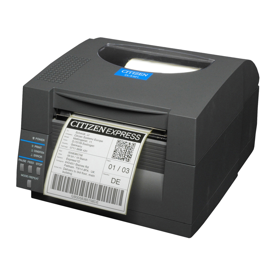
Citizen CL-S521 User Manual
Thermal & barcode printer
Hide thumbs
Also See for CL-S521:
- User manual (66 pages) ,
- Quick start manual (4 pages) ,
- Features & specifications (2 pages)
Table of Contents
Advertisement
Advertisement
Table of Contents
Troubleshooting

Related Manuals for Citizen CL-S521


Summary of Contents for Citizen CL-S521
- Page 1 SER'S ANUAL Thermal Label & Barcode Printer CL-S521...
-
Page 2: Table Of Contents
Normal Operating Mode -----------------------------------------------------------19 Setting the Media ------------------------------------------------------------------ 21 Mode Settings ---------------------------------------------------------------------- 25 Emulation Auto Detect: Cross-Emulation Manually Selecting the Printer Emulation ---------------------------------------- 38 Chapter 3 Printer Adjustments Sensor Adjustments --------------------------------------------------------------- 39 Media Thickness Adjustment ----------------------------------------------------- 42 Media Width Adjustment ---------------------------------------------------------- 43... -
Page 3: Introduction
INTRODUCTION Thank you very much for purchasing Citizen's compact direct thermal label & barcode printer Model CL-S521 that offers high performance printing at 6 inches per second on 4.1 inch media at very low cost. Main Features <High-speed, high-quality printing>... -
Page 4: Compliance Statement For European Users
Operation of this equipment in a residential area is likely to cause harmful interference in which case the user will be required to correct the interference at his own expense. The model name printed on the CL-S521 rating label is JM30-M01. -
Page 5: Emi Compliance Statement For Canadian Users
EMI COMPLIANCE STATEMENT FOR CANADIAN USERS This Class A digital apparatus complies with Canadian ICES-003. This equipment generates and uses radio frequency energy and if not installed and used properly, that is, in strict accordance with the manufacturer's instructions, may cause interference to radio and television reception. -
Page 6: Important Safety Instructions
Important Safety Instructions Read all of these instructions and save them for later reference. Follow all warnings and instructions marked on the product. Unplug this product from the wall outlet before cleaning. Do not use liquid or aerosol cleaners. Use a damp cloth for cleaning. -
Page 7: Notice
We are not liable for any damage caused by user's erroneous use of the printer and inadequate environment. Data residing in the printer is temporary. Therefore, all data will be lost if power is lost. We are not liable for any damage or loss of profits caused by data loss due to failures, repairs, inspections, etc. -
Page 8: Safety Instructions
Do not use a power voltage or frequency other than those specified. Do not plug/unplug the power cord or attach/detach the interface cable by simply grabbing the power cord or interface cable. Do not pull or carry the printer when the tension of the power cord or interface cable is increased. -
Page 9: Precautions When Installing The Printer
Do not put anything on the top of printer. Do not place the printer near a radio or television, and do not use the same wall outlet for the printer and radio or television. Radio or television reception could be adversely affected. -
Page 10: Chapter 1 Setup
Confirmation of Carton Contents Removing the Packing Material The printer is shipped with adhesive tape in place to hold the top cover closed. Simply remove the two pieces of tape on either side of the top cover. Then simply open the cover by lifting up and tipping it backwards. -
Page 11: Part Names And Functions
The printer may cause injury or property damage if dropped. Be sure to grip the printer housing firmly when taking it out of the carton. Do not grip the printer by the foam packing material which may break, causing the printer to drop. - Page 12 (p.42) 5 Media holder bar The media is supported by the media holder bar when installed in the printer. 6 Media holder guide This guide is moved horizontally to match the media size. The guide can be sliding it from the holder bar.
-
Page 13: Thermal Printhead
Setting sensor positions (p.23) Sensor Adjustments (p.39) Media Setting (p.24) = Thermal printhead This is the printhead. Avoid touching this with your fingertips and leaving grease or dirt on the printhead surface. ~ Platen Interlocked with the thermal printhead, it feeds media backwards or forwards. -
Page 14: Operation Panel
This is lit when the printer is able to print. (green) 3 CONDITION LED This is on when selecting settings. (orange) 4 ERROR LED This is lit or flashes when the printer is in an alarm or error status. (red) 5 PAUSE key This temporarily stops printing. 6 FEED key This key feeds the media to the top of the next label or form. -
Page 15: Rear View
This receives serial transmission of data from a host computer. 2 USB interface This receives USB transmission of data from a host computer. 3 Power switch The is the power switch for the printer. 4 Power cord inlet The connector of the enclosed power cord is connected here. Setup... -
Page 16: Connection To Power
Setup Connection to Power 1. Check that the power switch to the printer is turned OFF. 2. Connect the connector of the power cord to the power cord inlet on the printer. 3. Insert the plug of the power cord in the AC outlet. -
Page 17: Connection To A Computer
1. Turn OFF both power switches of the printer and the computer. 2. Connect one end of the interface cable to the interface connector on the back of the printer and secure it with locks or locking screws, where available. -
Page 18: Chapter 2 Printer Operation
Printer Operation Power ON/OFF Turning on the power 1. Turn on the power switch on the back of the printer. 2. The POWER and PRINT LED are lit. Operation Panel Power Switch Turning off the power 1. Turn off the power switch on the back of the printer. -
Page 19: Normal Operating Mode
The control keys activate the following functions. 1 PAUSE key: Temporarily pauses printing • When this key is pushed once, the PRINT LED turns off and the printer temporarily pauses. • When it is pushed during printing, the printer pauses after the label currently being printed is issued. -
Page 20: Led Functions
Normal Operating Mode LED Functions In addition to normal operating mode, when an abnormal condition is detected in the printer, an alarm sounds and each LED either lights up or flashes to indicate the type of error. 1 POWER LED It lights up when printer power is turned on. -
Page 21: Setting The Media
* If the label pitch is 1 inch or less, set the Small Media Adjustment menu to ON and match it to the label that uses the value of the Small Media Length menu. Printer Operation Continuous media Notch detection... -
Page 22: Installing The Media
4. Set the media roll and media holder in to the printer as shown above. It is advisable to pull a length of media forwards and through the mechanism ready for later positioning. -
Page 23: Printer Operation
Adjust the position of the sensor so that the reflective sensor marker of the bottom sensor is at the center of the black mark of the media as shown below. Media Bottom sensor Black mark Platen Printer Operation Setting the Media Upper sensor Bottom sensor Movable media guide Front... - Page 24 8. Lower and lock the head unit. Align it with the width of the media that has been set, then set the media width and media thickness adjustment dials. See “Chapter 3 Printer Adjustments”. Head unit Media width adjustment 9. With the power switched on, push the FEED key to feed the media.
-
Page 25: Mode Settings
Turning power on while pushing the MODE/REPEAT key. HEX Dump Mode When using label media Turn on printer power while pushing the STOP key. If the PRINT LED has begun to flash slowly, release the STOP key, and then the printer enters HEX DUMP mode. -
Page 26: Self Print Mode
(p.43) Self Print Mode Performing a self test print is an easy way to check on the state of printer setting and printing quality. Install the media as explained in “Installing the Media” and then operate the printer as follows. -
Page 27: Menu Setup Mode
Menu Setup Mode If the printer power is turn on while the MODE/REPEAT key is pressed, the printer enters menu setup mode. In this mode, the printer’s configuration can be changed using the VuePrint Menu System. During menu setting mode, the PRINT LED and CONDITION LED are on. - Page 28 Printer Operation ® Mode Settings [Datamax Emulation] Menu Setting Flow Chart The following is a flow chart showing the CL-S521 VuePrint menu system. 7 Datamax ® Emulation Menu Setup Mode (p.27) MODE/REPEAT key + Power on Do you Printing during top menu...
- Page 29 Press FEED key for 3 seconds Initialization of the content of the settings Are you sure? (Initialization to the settings when the printer was shipped.) Printing the contents of the present setting EXIT Do you want to change "Global Config Menu"...
- Page 30 (p.28) Menu Setting Flow Chart (p.28) Shown below is a sample menu output from the CL-S521 VuePrint menu system. This particular example is changing the print speed and print darkness then continues through the remainder of the “Print Setup” menu.
- Page 31 <Example of CL-S521 Datamax * The settings of the Symbol Set can be changed only by a command. Note: Citizen continually enhances its printers with new options and settings based on our customer's requests. Extra or changed menu items may appear on the above print out in some case.
-
Page 32: Menu Setting Table
Emulation] Menu Setting Table Global Config menu - allows you to switch between 3 complete ‘config sets’ contained within the printer. Page Setup Menu - allows you to change settings related to the media or print quality. System Setup Menu - allows you to change settings for the printer hardware and basic control systems. - Page 33 2400 None None Sets the communication parity of the serial interface. Even 8 bits 8 bits Sets the character length of the serial 7 bits interface. Printer Operation Mode Settings ® [Datamax Emulation] ® /Zebra ® compatibility ® IClass ®...
- Page 34 RS-232C Stop bit RS-232C X-ON IEEE1284 Web Monitor* USB Device Class USB VCOM Protocol * Displayed only when an optional LAN board is connected to a printer. Default Menu Remarks 1 bit 1 bit Sets the stop bit of the serial interface.
- Page 35 When on, prevents software commands from changing the values set by the VuePrint menu Prevents the control panel from affecting the printer's configuration. (User "lock-out") Selects whether or not to initiate media measurement when the power in ON. Activates/deactivates the CI command.
- Page 36 Printer Operation Mode Settings ® [Zebra Emulation] Top Menu Sub Menu After Print AutoConfigure Function Select Cutter Action* Paper Position Mode/Repeat Key Interface RS-232C Baud RS-232C Parity RS-232C Length RS-232C Stop bit RS-232C X-ON IEEE1284 * Effective only when the optional unit is attached.
- Page 37 Top Menu Sub Menu Web Monitor* USB Device Class USB VCOM Protocol * Displayed only when an optional LAN board is connected to a printer. Default Menu Remarks Auto Auto Selecting the web monitor function. Printer Printer Selects the USB device class.
-
Page 38: Emulation Auto Detect: Cross-Emulation Tm
Alternatively, you can use the “Quick Switch” option as follows: 1. Turn on the printer holding down PAUSE and FEED keys together. The printer will beep three times and the CONDITION LED will flash. -
Page 39: Chapter 3 Printer Adjustments
STOP key simultaneously. 2. After the PRINT LED and CONDITION LED light up, release the keys to change the printer to sensor adjustment setting mode. Sensor Selection Method (Transparent To switch from transparent to reflective sensor, ensure the CONDITION LED is lit then hold down the MODE/REPEAT key and then press the STOP key. -
Page 40: Printer Adjustments
Printer Adjustments Sensor Adjustments Media Setting (p.23) Sensor Selection Method (Transparent Reflective) (p.39) Adjusting the Transparent sensor 1. Push the large blue-head open lever to open the head unit and sensor arm, then return only the sensor arm to its original position. - Page 41 CONDITION LED return to their original status. If it does not stop normally (adjustment impossible), the CONDITION LED and ERROR LED flash. 6. If the STOP key is pushed, it exits sensor adjustment mode. Printer Adjustments Sensor Adjustments Black mark Reflective sensor marker...
-
Page 42: Media Thickness Adjustment
Self Print Mode (p.26) Media Thickness Adjustment It may be necessary to adjust the printer according to the thickness of the media being used. This can be done easily by rotating the media adjustment dial to improve the print quality. -
Page 43: Media Width Adjustment
The head pressure varies according to the width of the media being printed. The head pressure balance must be adjusted according to media width so that constant head pressure is applied to the head. With this printer, it can be adjusted easily by turning the media width adjustment dial. -
Page 44: Cleaning
Do not use any solvent other than ethyl alcohol. Solvents such as benzene, acetone and thinner will dissolve plastic parts and destroy the thermal printhead, platen and much of the printer! Try to avoid using "excessive amounts" of ethyl alcohol to clean the platen. -
Page 45: Chapter 4 Troubleshooting
Cleaning (p.44) Menu Setting Table (p.32) This chapter explains corrective actions taken when the printer malfunctions or when an error message is displayed. Items to check when a malfunction occurs When the printer malfunctions during operation, take corrective action with reference to the following table. -
Page 46: Troubleshooting
If a label is stuck to the head, remove Note: Do not use a metal object to remove a label stuck to the inside of the printer. (This may damage the print head.) If adhesive label material is stuck to the thermal printhead, remove it with a soft cloth soaked in ethyl alcohol. -
Page 47: Appendixes
Appendixes Specifications Item Printing Printing method Resolution Max. print width Max. print length Print density Printing speed Printing speed setting Print mode Batch mode Tear off mode Cut mode Peel mode Media Types of media Kinds of media Recommended media Max. - Page 48 Appendixes Specifications Item Bar code One-dimension ® (for Zebra emulation) Two-dimension Font ® (for Datamax emulation) Font ® (for Zebra emulation) Symbol set Control language Outline of electronic devices RAM (for Datamax ® ® RAM (for Zebra emulation) Media detection Transparent sensor sensors Reflective sensor...
- Page 49 Item Power (standards) 100V version 220V version Environment Operating temperature conditions: Storage temperature conditions: External dimensions Weight Accessories Option *1: Options can be separately purchased. *2: When a media pitch of less than 1 inch is used, activate the “Small Media Adjustment” setting in the “Page Setup.” *3: The OCR font may have a low recognition rate according to the reader.
-
Page 50: Interfaces
There are three types of computer interfaces, and these are connected to devices suited to each type of interface. The printer can also be connected to a computer by the optional Ethernet and wireless LAN. Serial Interface... - Page 51 XON/XOFF Protocol Requirements to output X-ON code • Communication is possible when the power is on. • When the receive buffer has less than 128 byte available, XOFF code is output, then the receive buffer has at least 1024 bytes available. Requirements to output the X-OFF code •...
-
Page 52: Usb Interface
Appendixes Interfaces USB Interface Specifications Standards Transmission speed Receive buffer Connector Signal line and pin arrangement Pin No. Complies with Universal Serial Bus Specification Compatible with 12Mbps (full speed) transmission 16kB DUSB DUSB-BRA42-T1 1(DDK) Signal code Signal Function VBUS USB power USB power (+5V) Signal line + + signal line... -
Page 53: Parallel Interface (Option)
16kB Transmission modes Compatible mode It is an asynchronous forward direction of the byte width (from host to printer) channel, and the interface line of the data is operated in accordance with signal line definitions of Centronics. NIBBLE mode Nibble mode is asynchronous reverse channel communication with data transmission controlled by the host computer. -
Page 54: Parallel Port Status Signals When An Error Occurs
Appendixes Interfaces Parallel port status signals when an error occurs The status of a signal line will not be changed in bi-directional mode such as nibble or ECP mode. Error Paper end Error other than paper end • Head open •... - Page 55 [While receiving INIT signal] Min. 10 to 15 sec *Init BUSY *Ack *Fault SELECT Note: If the *Init signal does not have width of 10 to 15 µ sec or more, it cannot act as an Init signal. If it is lower, the *Init signal is ignored. BUSY starts up when the *Init signal is perceived.
- Page 57 363 Van Ness Way, Suite 404 Torrance, CA 90501. USA Tel: (310) 781-1460 Fax:(310) 781-9152 http://www.citizen-systems.com Mettinger Strasse 11 D-73728, Esslingen Germany Tel: +49 (0) 711 3906 400 Fax:+49 (0) 711 3906 405 http://www.citizen-europe.com 6-1-12, Tanashi-cho, Nishi-Tokyo-shi Tokyo, 188-8511. Japan...
Need help?
Do you have a question about the CL-S521 and is the answer not in the manual?
Questions and answers