Table of Contents
Advertisement
GETTING STARTED GUIDE
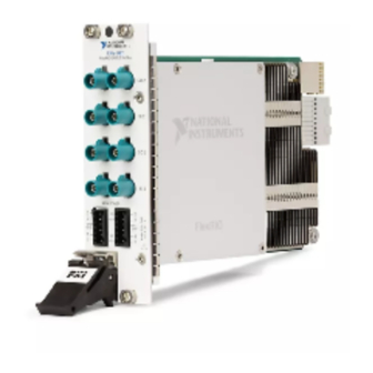
PXIe-1486
FlexRIO FPD-Link Interface Module
This document explains how to install and configure the following variants of the PXIe-1486:
•
PXIe-1486 FlexRIO FPD-Link
•
PXIe-1486 FlexRIO FPD-Link
•
PXIe-1486 FlexRIO FPD-Link
After completing the tasks described in this document, you will have a hardware and driver
setup that allows you to design and test your software application.
Note
If you purchased the PXIe-1486 as part of an NI system, refer to your system
documentation for application-specific instructions for using the PXIe-1486.
Contents
FlexRIO Documentation and Resources...................................................................................2
Preparing the System Components........................................................................................... 3
Unpacking the Kit............................................................................................................. 3
Verifying the Kit Contents................................................................................................ 3
System Components..........................................................................................................3
Prerequisites.............................................................................................................................. 4
Verifying the System Requirements..................................................................................4
Installing the Software.............................................................................................................. 4
Installing the PXIe-1486........................................................................................................... 4
Cabling the PXIe-1486..............................................................................................................4
Configuring the PXIe-1486 in MAX........................................................................................ 8
Accessing FlexRIO with Integrated I/O Examples...................................................................9
Common FlexRIO with Integrated I/O Examples.......................................................... 10
Component-Level Intellectual Property (CLIP)..................................................................... 10
Front Panels, Connectors, and Block Diagrams......................................................................11
PXIe-1486 Deserializer Front Panel, Connectors, and Block Diagram..........................11
PXIe-1486 Serializer Front Panel, Connectors, and Block Diagram..............................14
PXIe-1486 SerDes Front Panel, Connectors, and Block Diagram................................. 17
FPGA Carrier Block Diagram.........................................................................................20
Where to Go Next................................................................................................................... 20
NI Services.............................................................................................................................. 20
™
Deserializer
™
Serializer
™
SerDes
Advertisement
Table of Contents

Related Manuals for NI PXIe-1486


Summary of Contents for NI PXIe-1486
-
Page 1: Table Of Contents
After completing the tasks described in this document, you will have a hardware and driver setup that allows you to design and test your software application. Note If you purchased the PXIe-1486 as part of an NI system, refer to your system documentation for application-specific instructions for using the PXIe-1486. Contents FlexRIO Documentation and Resources...................2... -
Page 2: Flexrio Documentation And Resources
FlexRIO Documentation and Resources Use the following resources to find more information about the PXIe-1486. All product documentation can be found at ni.com/manuals or in LabVIEW by clicking Help. Table 1. FlexRIO Documentation and Resources Document Contents • Installation instructions... -
Page 3: Preparing The System Components
Unpack any other items and documentation from the kit. Store the device in the antistatic package when the device is not in use. Verifying the Kit Contents Verify that the following items are included in the PXIe-1486 kit. Figure 1. Kit Contents 1. PXIe-1486 Module 3. -
Page 4: Prerequisites
LabVIEW FPGA Module • FlexRIO Installing the PXIe-1486 For instructions on how to install your PXIe-1486 into the chassis, refer to your chassis documentation, available at ni.com/manuals. Cabling the PXIe-1486 Complete the following steps to connect your PXIe-1486 to other system components. - Page 5 This allows you to supply external power. If you do not connect an external power source, devices connected to PXIe-1486 can be powered by the chassis backplane. For Serializer or SerDes modules, use a copper conductor wire to connect a power sink to the serial output channel's corresponding pin on the AUX power connector.
- Page 6 1. PXIe-1486 Deserializer Module 4. FAKRA Female Code Z to Serial Device Connector Cable 2. Camera or Serial Device 5. Power Connector Wire, Grounding 3. Power Source 6. Power Connector Wire, Positively Charged 6 | ni.com | PXIe-1486 Getting Started Guide...
- Page 7 4. FAKRA Female Code Z to FAKRA Female Code Z Cable 2. Engine Control Unit (ECU) 5. Power Connector Wire, Grounding 3. Power Sink 6. Power Connector Wire, Positively Charged PXIe-1486 Getting Started Guide | © National Instruments Corporation | 7...
-
Page 8: Configuring The Pxie-1486 In Max
Configuring the PXIe-1486 in MAX Use Measurement & Automation Explorer (MAX) to configure your NI hardware. MAX informs other programs about which NI hardware products are in the system and how they are configured. MAX is automatically installed with FlexRIO. -
Page 9: Accessing Flexrio With Integrated I/O Examples
In the configuration tree, expand Devices and Interfaces to see the list of installed NI hardware. Installed modules appear under the name of their associated chassis. Expand your Chassis tree item. MAX lists all modules installed in the chassis. Your default names may vary. -
Page 10: Common Flexrio With Integrated I/O Examples
CLIP allows your IP to communicate directly with both the FPGA VI and the external adapter module connector interface. The PXIe-1486 ships with socketed CLIP items that add module I/O to the LabVIEW project. 10 | ni.com | PXIe-1486 Getting Started Guide... -
Page 11: Front Panels, Connectors, And Block Diagrams
FlexRIO Terminal Name SI 0 Serial input to internal deserializer SI 1 Serial input to internal deserializer SI 2 Serial input to internal deserializer SI 3 Serial input to internal deserializer PXIe-1486 Getting Started Guide | © National Instruments Corporation | 11... - Page 12 Serial input to internal deserializer SI 7 Serial input to internal deserializer Figure 6. PXIe-1486 Deserializer AUX Power Connectors Table 3. PXIe-1486 Deserializer AUX Power Connectors Signal Descriptions Signal Pin Description Power supply for channel SI 0 Power supply for channel SI 1...
- Page 13 Select None SI 7 CSI-2 Data Des7 SI 7 Deserializer GPIO DS90UB954 SI 7 Deserializer I2C / Des7_I2C Internal (12 V) Des7_RefClk Aux Power Select None Aux Power Power PXIe-1486 Getting Started Guide | © National Instruments Corporation | 13...
-
Page 14: Pxie-1486 Serializer Front Panel, Connectors, And Block Diagram
SO 1 SO 5 SO 2 SO 6 SO 3 SO 7 AUX POWER Table 4. PXIe-1486 Serializer Front Panel Connectors Signal Descriptions Signal Name Description FlexRIO Terminal Name SO 0 Serial output from internal serializer SO 1 Serial output from internal serializer... - Page 15 Power sink for channel SO 3 Power sink for channel SO 4 Power sink for channel SO 5 Digital/chassis grounding Digital/chassis grounding Power sink for channel SO 6 Power sink for channel SO 7 PXIe-1486 Getting Started Guide | © National Instruments Corporation | 15...
- Page 16 SO6 Serializer I2C / Ser6_I2C Aux Power Ser6_RefClk Select None SO 7 CSI-2 Data Ser7 SO 7 Serializer GPIO DS90UB953 SO 7 Serializer I2C / Ser7_I2C Aux Power Ser7_RefClk Select None Aux Power Power 16 | ni.com | PXIe-1486 Getting Started Guide...
-
Page 17: Pxie-1486 Serdes Front Panel, Connectors, And Block Diagram
Serial input to internal deserializer SO 1 Serial output from internal serializer SI 1 Serial input to internal deserializer SO 2 Serial output from internal serializer SI 2 Serial input to internal deserializer PXIe-1486 Getting Started Guide | © National Instruments Corporation | 17... - Page 18 Table 6. PXIe-1486 SerDes Front Panel Connectors Signal Descriptions (Continued) Signal Name Description FlexRIO Terminal Name SO 3 Serial output from internal serializer SI 3 Serial input to internal deserializer Figure 12. PXIe-1486 SerDes AUX Power Connectors Table 7. PXIe-1486 SerDes AUX Power Connectors Signal Descriptions...
- Page 19 Select None SI 3 CSI-2 Data Des3 SI 3 Deserializer GPIO DS90UB954 SI 3 Deserializer I2C / Des3_I2C Internal (12 V) Des3_RefClk Aux Power Select None Aux Power Power PXIe-1486 Getting Started Guide | © National Instruments Corporation | 19...
-
Page 20: Fpga Carrier Block Diagram
Before you can use your system, you need to configure the connection between the serial device and the PXIe-1486, build your application, then test and troubleshoot your application. Contact NI for more information about developing the software resources to operate your system. - Page 21 NI product. Product registration facilitates technical support and ensures that you receive important information updates from NI. NI corporate headquarters is located at 11500 N Mopac Expwy, Austin, TX, 78759-3504, USA. PXIe-1486 Getting Started Guide | © National Instruments Corporation | 21...
- Page 22 . You can find patents.txt ni.com/patents information about end-user license agreements (EULAs) and third-party legal notices in the readme file for your NI product. Refer to the Export Compliance Information at for the NI global trade compliance policy and how ni.com/legal/export-compliance...
Need help?
Do you have a question about the PXIe-1486 and is the answer not in the manual?
Questions and answers