Table of Contents
Troubleshooting

Related Manuals for Canon CR-S700R


Summary of Contents for Canon CR-S700R
- Page 1 PUB. DIE-0545-000A CR-S700R Robotic Camera System Instruction Before using the product, carefully read this Instruction Manual and be sure to Manual use the product correctly. Retain the Instruction Manual for future reference.
-
Page 2: Table Of Contents
Conventions Used in this Document ··············································································································· 10 System Chart ··································································································································································· 11 Names of Parts ······························································································································································· 12 CR-S700R Robotic Camera Head ····················································································································· 12 URC-S1 Camera Remote Rain Cover (optional) ····························································································· 13 CR-BP100 Base Plate (optional) ·························································································································14 3 System Connections ················································································································ 15 Preparations ····································································································································································... - Page 3 Transportation/Installation ································································································································ 44 Testing the Operation Post-Installation ················································································································ 46 Removing the Camera Head ····································································································································· 46 5 Additional Information ·········································································································· 47 Troubleshooting ····························································································································································· 47 Specifications ·································································································································································· 48 CR-S700R Robotic Camera Head ···················································································································· 48 Power Input Pin Layout ······································································································································ 48...
- Page 4 6 Appendix·································································································································· 49 Torque Value Guidelines for Tightening Bolts ···································································································· 49 Gear Ring Attachment Positions······························································································································ 49 Connection/Installation Checklist ··························································································································· 50 Detailed Dimensions ···················································································································································· 52 CR-S700R Robotic Camera Head ···················································································································· 52 CR-BP100 Base Plate ·········································································································································· 53 7 Index ········································································································································· 54...
-
Page 5: Important Safety And Handling Instructions
Contact If foreign objects (metallic objects, liquids, a Canon sales representative as soon as possible. etc.) get inside the product. WARNING Denotes the risk of serious injury or death. Transportation/Installation Power supply ... -
Page 6: Handling Precautions
1 Important Safety and Handling Instructions Handling Precautions Maintenance and inspection product’s power specifications. Using an unsuitable power cable may cause electric shock and fire. Unplug the power cable from the power outlet Make sure to turn off the product before before cleaning it using a dry cloth. -
Page 7: Disclaimers
For further information on repairs, maintenance, or adjustments not mentioned in this instruction manual, contact a Canon sales representative. Note that Canon may be unable to undertake servicing or repair of a product if it is modified without consulting Canon. -
Page 8: Introduction
Bracket Eyepiece Camera Bracket N3 Cable LAN Cable USB Cable (type C) and USB Cable (for EOS-1D X Mark II) USB Cable (type C) DC Coupler Ferrite Cores (x2) (for EOS-1D X Mark III) * Comes pre-attached to the CR-S700R. -
Page 9: Optional Accessories
2 Introduction Components Optional Accessories URC-S1 Camera Remote CR-BP100 Base Plate and Camera Remote Rain Cover M8 fixation bolts (x4) Application CR-A100 About the Camera Remote application CR-A100 (optional) Using the Camera Remote application you can control multiple robotic camera systems and EOS cameras. You can also use a controller to operate the system and check a streamed image with a very small lag while recording. -
Page 10: Overview
Overview Overview Thank you for purchasing this Canon robotic camera system. This instruction manual covers the CR-S700R Robotic Camera Head and CR-G100 IP Camera Controller, how to mount and connect a camera and how to install the system at the shooting location. For details about the CR-G100’s web setup tool, refer to the CR-G100 instruction manual. For the latest information about this product, please visit your local Canon website. -
Page 11: System Chart
System Chart Main capture camera (sold separately) Web setup tool (CR-G100) Eyepiece camera (commercially available) Camera Remote Application CR-A100 (sold separately) CR-G100 IP Camera Controller Wide view camera (commercially available) FTP server (commercially available) Ethernet CR-S700R Robotic Camera Head Power supply... -
Page 12: Names Of Parts
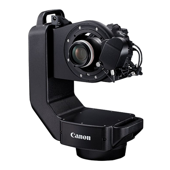
2 Introduction Names of Parts Names of Parts CR-S700R Robotic Camera Head Camera head (A 17) Handle (A 17) Camera rotator (A 17) Zoom unit (A 23) Logo plate The plate can be installed upside down if necessary. -
Page 13: Urc-S1 Camera Remote Rain Cover (Optional)
2 Introduction Names of Parts Safety wire (A 28, 44) Zoom unit cable (A 28) Power cable (A 34) LAN cable (A 34) Head interface cable (A 34) Screw holes for M8 fixation bolts (12 mm (0.47 in.) deep, x4) ... -
Page 14: Cr-Bp100 Base Plate (Optional)
2 Introduction Names of Parts CR-BP100 Base Plate (optional) (A 41) Screw holes for safety eye bolt (x4) Screw holes for camera head fixation screws (x4) Screw holes for V-type attachment mount (3/8” (x9), M5 (x10)) Screw holes for 50 mm (2.0 in.) clamp (∅ 10 mm (0.39 in.), x6) Screw holes for 50 mm or 60 mm (2.0 in. -
Page 15: System Connections
Prepare the following required equipment in advance. Main capture camera and lens that are both compatible with this product* * Sold separately. For the latest information on compatible cameras and lenses, please visit your local Canon website. Gear ring (commercially available, A 9) ... -
Page 16: Overview Of The Installation Process
3 System Connections Preparations Using the optional base plate secured with clamps (one of the following): • Clamps for 50 mm (2.0 in.) pipes (M10 bolts/nuts, 2 sets) Clamps for 50 mm/60 mm (2.0 in./2.4 in.) pipes (M12 bolts/nuts, 2 sets) ... -
Page 17: Unpacking The Supplied Equipment
3 System Connections Unpacking the Supplied Equipment Unpacking the Supplied Equipment Grab the camera head by the handle, remove it from the package and place it on a stable work surface. To transport the camera head after use, carefully pack it in the ... - Page 18 3 System Connections Removing the Units Originally Attached to the Camera Head Hold the IP controller from below and slide it in the direction of the arrow to remove it. Loosen the fastener and release the cables that were tied together.
-
Page 19: Preparing The Camera Unit
For the latest information on lenses and cameras that can be used as main capture camera, please visit your local Canon website. Attaching a Lens to the Main Capture Camera and Inserting the Recording Media For details about operating the camera, refer to the instruction manual of the camera used. -
Page 20: Connecting The Power Supply To The Main Capture Camera
3 System Connections Preparing the Camera Unit Some settings cannot be changed using the Camera Remote application after the installation is completed. Make sure to change all the necessary settings on the main capture camera and the lens before the final installation. -
Page 21: Attaching The Main Capture Camera To The Camera Mounting Bracket
3 System Connections Preparing the Camera Unit Attaching the Main Capture Camera to the Camera Mounting Bracket Attach the camera mounting bracket to the bottom of the camera. For details about operating the lens, refer to the instruction manual of the lens used. Lenses with a Lens Supporter Loosen the hex head bolts (M5, x3) holding together the Bottom... - Page 22 3 System Connections Preparing the Camera Unit Final situation after the procedure Lenses without a Lens Supporter After adjusting the positioning element as necessary, align Bottom the camera supporting bracket’s hex head bolt (1/4”) with the camera’s tripod socket and screw it in only partially using the 4 mm hex wrench.
-
Page 23: Attaching The Optional Rain Cover's Front Ring
3 System Connections Attaching the Optional Rain Cover’s Front Ring Attaching the Optional Rain Cover’s Front Ring When using the optional URC-S1 Camera Remote Rain Cover, attach the rain cover’s front ring to the subject side of the camera rotator. Front Thread washers onto the hex head bolts supplied with the rain cover (M5, x4) and attach the bolts to the front ring. -
Page 24: Attaching The Zoom Unit To The Camera Head
3 System Connections Attaching the Zoom Unit Attaching the Zoom Unit to the Camera Head Turn the camera rotator clockwise so the hole for the zoom unit shaft is on top. Insert the zoom unit shaft into the camera rotator. ... -
Page 25: Mounting The Camera Unit
3 System Connections Mounting the Camera Unit Mounting the Camera Unit Replacing the Camera Rotator’s Mounting According to the Installation Position The camera rotator is shipped with the mounting for the camera bracket in a position appropriate for using the camera in upright mode. - Page 26 3 System Connections Mounting the Camera Unit Pass the camera head’s cable assembly through the rain cover’s rear cover. Pass the cable assembly though the rear cover’s smaller opening. Reattach the part you removed in step 1 to the cable clamp and secure it using hex head bolts (M5, x2).
-
Page 27: Mounting The Camera Unit On The Camera Head
3 System Connections Mounting the Camera Unit Mounting the Camera Unit on the Camera Head Turn the camera rotator so the mounting for the camera mounting bracket is at the bottom. Insert the camera unit’s lens through the camera rotator and slide camera mounting bracket all the way into the camera rotator’s mounting. -
Page 28: Attaching A Gear Ring To The Lens And Fixing The Zoom Unit
3 System Connections Attaching a Gear Ring to the Lens and Fixing the Zoom Unit Attaching a Gear Ring to the Lens and Fixing the Zoom Unit Attaching a Gear Ring (commercially available) to the Lens Turn the camera rotator counter-clockwise so the main capture camera is on top. Turn the lens’s zoom ring until the Telephoto end. - Page 29 3 System Connections Attaching a Gear Ring to the Lens and Fixing the Zoom Unit Connect the camera head’s zoom unit cable to the terminal on the camera unit. If the zoom unit is attached to the camera rotator’s subject side, pass the zoom unit cable through the camera rotator to connect it.
-
Page 30: Attaching The Ip Controller
3 System Connections Attaching the IP Controller Attaching the IP Controller Turn the camera rotator clockwise so the bottom of the camera is on top. Place the IP controller on top of the camera mounting bracket and slide it in the direction of the arrow. Secure it in place using hex head bolts (M3, x4). -
Page 31: Attaching Other Accessories
3 System Connections Attaching Other Accessories Attaching Other Accessories You can attach a commercially available wide view camera and eyepiece camera (A 9) if necessary. If you do not plan to use such accessories, skip to the following section, Connecting the Cables (A 34). -
Page 32: Attaching An Optional Eyepiece Camera
3 System Connections Attaching Other Accessories Final situation after the procedure (from the side where the base unit’s terminals are visible) Attaching an Optional Eyepiece Camera Loosen the eyepiece camera bracket’s hex head bolts (M3, x4) but not too much. ... - Page 33 3 System Connections Attaching Other Accessories Connect the right angle connector of the USB cable (supplied with the eyepiece camera) to the eyepiece camera. Pass the cable through the bracket’s cable removal prevention fitting and secure the bracket in place using hex head bolts on both sides of the rear part (M3, x2).
-
Page 34: Connecting The Cables
Use the following diagram as a reference to perform the necessary connections. In this example, an Ethernet hub is used for network connections to the control PC and an FTP server. (5) LAN cable (supplied) DC coupler CR-S700R (4) USB Type C cable Robotic Camera Head (supplied) -
Page 35: Connecting The Camera Head
3 System Connections Connecting the Cables Connecting the Camera Head Turn the camera rotator clockwise so the IP controller is on top. Connect the head interface cable to the IP controller’s HEAD terminal (1). Connect a LAN cable to the IP controller’s (Ethernet) terminal (2). -
Page 36: Standing Up The Camera Head
3 System Connections Connecting the Cables Standing Up the Camera Head Before connecting the camera head to a power source and network and checking the operation of the system, stand the camera head upright. To do so, attach the optional base plate to the camera head (A 41), or perform a provisional installation at the shooting location (A 44). -
Page 37: Turning The System On/Off
3 System Connections Connecting the Cables Place the ferrite core about 3 cm (1.2 in.) from the LAN cable’s connector. Loop the cable once and close the ferrite core. Connecting the Power Supply and Network Connect the 3-pin XLR connector of a commercially available AC adapter to the DC IN 24V terminal on the camera head (9). -
Page 38: Checking The System
3 System Connections Checking the System Checking the System Use the web setup tool on the control PC to check the operation of the robotic camera system and complete the necessary setup. For details about the web setup tool, refer to the CR-G100 instruction manual. Additionally, if you plan to use the Camera Remote application CR-A100 (sold separately), run the application and test the system’s operation before the final installation. -
Page 39: Attaching The Optional Rain Cover
3 System Connections Attaching the Optional Rain Cover Attaching the Optional Rain Cover When using the optional URC-S1 Camera Remote Rain Cover, for example for outdoor use, attach the front and rear covers to the rain cover. The front cover is different for the EF100-400mm lens and for other lenses. The optional URC-S1 Camera Remote Rain Cover is just a basic rain cover and does not make the system ... - Page 40 3 System Connections Attaching the Optional Rain Cover Attach the rear cover’s opening to the groove on the camera rotator’s camera side ring and pull the string to tightly close the cover’s opening. Use the fastener to hold the end of the string in place. Adjust the other rear cover opening so it reaches the waterproof structure of the camera head’s cable assembly.
-
Page 41: Attaching The Optional Base Plate
3 System Connections Attaching the Optional Base Plate Attaching the Optional Base Plate When using the optional CR-BP100 base plate, attach the base plate before installing the camera head. Depending on the installation location and position, attach also the eye bolts and clamps if necessary. Place the base plate surface with the “CAMERA SIDE”... -
Page 42: Replacing The Main Capture Camera And Lens
3 System Connections Replacing the Main Capture Camera and Lens Replacing the Main Capture Camera and Lens Removing the Camera Unit from the Camera Head Turn off the camera head (A 37). Disconnect the power cable and LAN cables from the camera head. If the camera head is standing upright, lay it down in the position just before connecting the cables, as shown in the “final situation”... -
Page 43: Removing The Main Capture Camera From The Camera Unit
3 System Connections Replacing the Main Capture Camera and Lens Removing the Main Capture Camera from the Camera Unit Turn the camera unit so the bottom of the camera is facing up and loosen the camera mounting bracket’s hex head bolts (M5, x3). Loosen the 1/4"... -
Page 44: Installation
4 Installation Installing the Camera Head 4 Installation Precautions when transporting/installing the system When transporting the camera head, always use two people to lift it, firmly grabbing the handles. Make sure the rotating parts are securely fixed and do not turn when transporting/installing the camera ... - Page 45 4 Installation Installing the Camera Head Locations where safety wires can be attached The following places on the camera head and base plate offer holes to which you can attach safety wires. Slits for cable tie bands 6 mm (0.24 in.) wide (x2) Wire attachment hole ∅...
-
Page 46: Testing The Operation Post-Installation
sure the surface where the camera is installed is perfectly level. Verify the camera head’s rotation range (A 48) and make sure the Canon logo on the base unit is aligned with the center of the camera head’s pan motion range. -
Page 47: Additional Information
If that does not solve the situation, there may be a problem with the system. Consult a Canon sales representative. The robotic camera system will not start. -
Page 48: Specifications
5 Additional Information Specifications Specifications CR-S700R Robotic Camera Head Temperature: -15 °C to 40 °C Operation environment Humidity: 90% RH or lower (without condensation) Rotation angle: -170° to 170°, where 0° is the front Rotation speed: 0.5 °/sec to 120 °/sec Rotation angle: -40°... -
Page 49: Appendix
6 Appendix Torque Value Guidelines for Tightening Bolts 6 Appendix Torque Value Guidelines for Tightening Bolts 63 N∙cm ±10% 298 N∙cm ±10% 507 N∙cm ±10% 1,230 N∙cm ±10% Gear Ring Attachment Positions Use the following table and illustrations as a reference when attaching the gear ring to the lens. Recommended Lens Type... -
Page 50: Connection/Installation Checklist
6 Appendix Connection/Installation Checklist Connection/Installation Checklist Use the following checklist to verify correct operation after connecting/installing the system. Pay attention to the fact that the items that can be checked before and after the installation are not the same. Before After Check item installation*... - Page 51 6 Appendix Connection/Installation Checklist Before After Check item installation* installation Camera Remote application CR-A100 ▢ ▢ The wide view camera’s image is displayed correctly. ▢ ▢ The eyepiece camera’s image is displayed correctly. ▢ The eyepiece camera’s image is sharp and clear. (If not, correct as necessary, —...
-
Page 52: Detailed Dimensions
6 Appendix Detailed Dimensions Detailed Dimensions CR-S700R Robotic Camera Head 260 (optical axis center) 260 (pan axis center) 4x M8... -
Page 53: Cr-Bp100 Base Plate
6 Appendix Detailed Dimensions CR-BP100 Base Plate 9xCU3/8-16 10xM5 DETAIL B DETAIL C SECTION A-A SCALE 1:2 SCALE 1:2... -
Page 54: Index
Index 7 Index (Ethernet) terminal ..........34, 35 Eye bolt (commercially available) ........ 14, 41 (N3 Remote) terminal ..........34, 35 Eyepiece camera ............9, 32, 35 Eyepiece camera bracket ............32 ALARM indicator ..............12, 47 EYEPIECE CAMERA terminal .......... 34, 35 Base plate (optional) ............ - Page 55 7 Index Testing the operation of the Operation environment ............48 main capture camera............. 38 Operation tests ................38 Tripod socket ................21 Overview of the installation process ......... 16 Troubleshooting ................ 47 Turning the system on/off ............ 37 Points to check/configure ............38 Positioning element ............
- Page 56 Canon Inc. 30-2, Shimomaruko 3-chome, Ohta-ku, Tokyo 146-8501, Japan The information in this document is verified as of January 2020. Subject to change without notice. © CANON INC. 2020...