Table of Contents
Advertisement
Quick Links
Advertisement
Table of Contents

Related Manuals for Stack ST8130 Series


Summary of Contents for Stack ST8130 Series
- Page 1 ST8130 Series Road Car Display Systems Users Guide Part No 542032-006...
- Page 3 Stack. Purpose of this manual This manual will help you install and use either model in the Stack ST8130 Series Road Car Display Systems. It explains how to set up and configure the system for your vehicle. Users Guide...
- Page 4 STACK ST8130 Road Car Display System Edition Notice This edition is for all versions of the ST8130 Series Road Car Display Systems distributed to customers worldwide. The units of measurement used to illustrate the use of the display systems in this edition are for the UK version.
- Page 5 Stack is a registered trademark of Stack Limited. Information in this publication is subject to change without notice and does not represent a commitment on the part of Stack Limited. No responsibility is accepted for error or omission. Copyright 1994, 1995, 1996, 1998 Stack Limited...
- Page 6 Stack Limited and its approved distributors provide a comprehensive Technical Help service to assist with your enquiries. Contact your local Stack branch or distributor. A current list of distributors can be found on the Stack websites at www.stackltd.com or www.stackinc.com...
- Page 7 STACK ST8130 Series Road Car Display Systems Contents Contents Preface Related Products From Stack Limited Who to Contact at Stack in Case of Difficulty Contents Chapter 1. Introducing the Display Systems ST8130 Models Chapter 2. Getting Started The Display Module...
- Page 8 Contents STACK ST8130 Series Road Car Display Systems Wheel speed sensor (ST670) Pulse Amplifier Interface (ST492) Fuel Tank Sender Lap timing sensor (optional) Trackside Infra-Red Lap Beacon (optional) Air Temperature Sensor (optional on ST8130 variant only) Wiring harness Checks and Alarms Chapter 6.
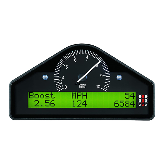
- Page 9 The models in the ST8130 Series are the ST8130, the ST813P and the ST8130M. The models combine an analogue tachometer with a digital display for the following performance parameters: 1.
- Page 10 How to use this Manual Stack recommends that you unpack and connect the components in the system before you install it in your vehicle. This will enable you to familiarise yourself with operating the display and configuring it for the vehicle in which you intend to install it.
- Page 11 STACK ST8130 Series Road Car Display Systems Chapter 1. Introducing the Display System This manual starts by taking you through the process of setting up the system before installation, operating the digital display, configuring the system, setting the alarm values and installing it in the vehicle. By the end of Chapter 2, you will have set up the system so that you will be assured that it is functioning normally.
- Page 12 Chapter 2. Getting Started STACK ST8130 Series Road Car Display Systems Chapter 2. Getting Started This chapter guides you through the initial unpacking and setting up of the equipment for pre-installation checks and familiarisation with its operation. Standard ST8130 Road Car Display System Items...
- Page 13 STACK ST8130 Road Car Display System Chapter 2. Getting Started Optional ST8130 Road Car Display System Items The ST8130 optional air temperature sensor consists of the following component: Quantity Description Air Temperature Sensor (ST765) The optional lap timing system consists of the following components:...
- Page 14 Chapter 2. Getting Started STACK ST8130 Series Road Car Display Systems Wiring Harness Each of the wires in the harness is labelled. Labels on Short Cables Connection To S1 to S4 Switches 1 to 4 Wheel speed input (ST492 or ST670)
- Page 15 STACK ST8130 Road Car Display System Chapter 2. Getting Started Connecting the Components 1. Connect the wiring harness to the display module. 2. Connect the four switches to the cables labelled S1 to S4. 3. Connect each of the sensors that you have purchased to the appropriate wire in the wiring harness, as shown above.
- Page 16 Chapter 3. Operating the Display System STACK ST8130 Series Road Car Display Systems Chapter 3. Operating the Display System This chapter takes you through the operation of the system so that you can familiarise yourself with its use before you install it in the vehicle.
- Page 17 STACK ST8130 Series Road Car Display Systems Chapter 3. Operating the Display System Display Layer 1 Display layer 1 shows: Fuel level • Note that when the amount of fuel in the tank is changed the displayed value changes slowly (about 1 litre every 5 seconds) to minimise the effects of fuel surge.
- Page 18 Chapter 3. Operating the Display System STACK ST8130 Series Road Car Display Systems Note that the minimum oil and water temperature for which the display gives a true reading is 12°C or 53°F. The unit displays temperatures that are less than this as 0°C or 32°F.
- Page 19 STACK ST8130 Series Road Car Display Systems Chapter 3. Operating the Display System • Fuel Pressure (Fuel P) • Current speed (MPH or km/h) Press Switch 3 to display layer 4. Display Layer 4 (ST8130 variant) Air T Batt 12.6V •...
- Page 20 Chapter 3. Operating the Display System STACK ST8130 Series Road Car Display Systems • Current speed (MPH or km/h) • Last lap time • Previous best lap time Press Switch 3 to change the display to layer 5. Display Layer 5...
- Page 21 STACK ST8130 Series Road Car Display Systems Chapter 3. Operating the Display System Peak Values (Tell Tales) The system can display the peak values (sometimes called ‘tell-tales’) that have been recorded during a run for all the monitored parameters. Peak values are updated only when the engine speed has exceeded its "gate value"...
- Page 22 Chapter 3. Operating the Display System STACK ST8130 Series Road Car Display Systems Displaying the Peak Values Press and hold Switch 1 to show the peak values for the parameters being displayed on the current layer. Release the switch to return to the normal display.
- Page 23 STACK ST8130 Series Road Car Display Systems Chapter 3. Operating the Display System Parameter New Peak Value Engine RPM Current value Wheel speed Current value Oil Pressure 999 PSI or 99.9 Bar Oil Temperature 0C or 0F Water Temperature 0C or 0F...
- Page 24 Chapter 3. Operating the Display System STACK ST8130 Series Road Car Display Systems Some of the warnings (see the following table) are triggered only after the engine speed has exceeded its "gate value" for RPM for at least one second. Blipping the engine may not be enough to trigger a warning.
- Page 25 STACK ST8130 Series Road Car Display Systems Chapter 3. Operating the Display System Displaying an Alarm When an alarm condition occurs, the built-in red warning light turns on and the digital display gives a warning message to show the type of alarm: Note that the low fuel warning is indicated by the amber light.
- Page 26 Chapter 3. Operating the Display System STACK ST8130 Series Road Car Display Systems Lap times The lap time for each lap is recorded either by the infra-red lap time sensor when passing the lap time beacon or when the driver presses Switch 4.
- Page 27 STACK ST8130 Series Road Car Display Systems Chapter 4. Configuring the Display System Chapter 4. Configuring the Display System Configuration mode You put the Display System into configuration mode by pressing Switches 1 and 2 together. This should give a display similar to the following: You then work through the configurable parameters in a preset sequence.
- Page 28 Chapter 4. Configuring the Display System STACK ST8130 Series Road Car Display Systems Switching Alarms on or off You can enable (switch on) or disable (switch off) each of the alarm warnings by pressing and holding Switch 1 and then pressing Switch 2.
- Page 29 STACK ST8130 Series Road Car Display Systems Chapter 4. Configuring the Display System Configurable Parameters The configurable parameters are displayed in the following order: Configurable Setting Required Switchable Parameter Parameter Shift RPM RPM at or above which the gear shift light...
- Page 30 Chapter 4. Configuring the Display System STACK ST8130 Series Road Car Display Systems Examples displays for each of the configuration items are shown below. Shift RPM: EDIT TEST Shift RPM 7000 Low Fuel: EDIT TEST Low Fuel 10 L Air Temperature (ST8130 variant):...
- Page 31 STACK ST8130 Series Road Car Display Systems Chapter 4. Configuring the Display System Low Fuel Pressure (ST8130P/M variant): EDIT TEST Low Fuel P Low Oil Pressure: EDIT TEST Low Oil P Fuel Level Calibration: Sw1 & 2 to calibrate Fuel Tank Sender...
- Page 32 Chapter 4. Configuring the Display System STACK ST8130 Series Road Car Display Systems Wheel Pulses and Circumferences Calculations for the ST8130 (ST492 Pulse Amplifier) You must supply a value for the wheel circumference that you obtain from one of the following calculations: 1.
- Page 33 STACK ST8130 Series Road Car Display Systems Chapter 4. Configuring the Display System 3. If you know the number of pulses generated for one mile (UK version only): 1609344 ÷ pulses per mile = wheel circumference Set the number of pulses per rev to 1.
- Page 34 Chapter 4. Configuring the Display System STACK ST8130 Series Road Car Display Systems If the sensor is mounted on a driveshaft or the propshaft, set the circumference to: Actual wheel circumference ÷ differential ratio -where the differential ratio is calculated as: crownwheel (ring) teeth ÷...
- Page 35 STACK ST8130 Series Road Car Display Systems Chapter 4. Configuring the Display System Configuring the Fuel Pressure Sensor (ST8130P/M variant) The default configuration for the ST8130P/M Display System is to interpret an input signal from a high range (0–150 PSI / 0–10 Bar) Fuel Pressure sensor.
- Page 36 You may wish to enter these values into the table on p31. If you ever have to return the unit for servicing, supplying the values from this table will allow Stack to automatically recalibrate the fuel display so that you will not have to repeat this process.
- Page 37 STACK ST8130 Series Road Car Display Systems Chapter 4. Configuring the Display System Note: The petrol (gas) pumps may shut off, if the petrol delivery is interrupted for a time. 2. Select the Fuel Tank Sender calibration display. Hold Switch 1 down and press Switch 2. This gives a display similar to...
- Page 38 Chapter 4. Configuring the Display System STACK ST8130 Series Road Car Display Systems The flowchart below summarises the steps in the calibration process. Start fuel tank calibration process: Press Switches 1 and 2. Switch 1 and 2 Set initial Tank Qty value using Switch 1 to decrease value or Switch 2 to increase value.
- Page 39 ST8130 Road Car Display System. Check with your Stack dealer if this is the case. When you wish to return to the normal display, press Switch 4.
- Page 40 Chapter 5. Installing the Display System STACK ST8130 Series Road Car Display Systems Chapter 5. Installing the Display System Who can install the Display System? The Display System can be installed by anyone competent in fitting electrical and mechanical accessories to cars.
- Page 41 STACK ST8130 Series Road Car Display Systems Chapter 5. Installing the Display System Fitting the Display Module The Display Module is fitted into a cut-out in the instrument panel/dashboard and secured using the two U-brackets at the rear. The dimensions for the cut-out are shown below. A full size template is supplied at the end of this manual.
- Page 42 Chapter 5. Installing the Display System STACK ST8130 Series Road Car Display Systems Switches The four switches are used to control the functions of the Display System. The normal functions of the four switches are: Switch Functions Switch 1 Show the peak values.
- Page 43 Stack Ltd can supply suitable external warning lights for installation in the dashboard (ST536/537) as well as shrouded versions that can be mounted on top of the dashboard (ST533/534).
- Page 44 Chapter 5. Installing the Display System STACK ST8130 Series Road Car Display Systems Connecting the Display System to the Ignition System The Display System can be connected to engines with a variety of ignition systems. These are shown in the following table.
- Page 45 STACK ST8130 Series Road Car Display Systems Chapter 5. Installing the Display System Standard contact breaker system Connect the ES (Engine Ignition ES (Engine System Speed) Wire Speed) wire to the negative terminal on the coil. Series Resistor Connection For systems which require series resistor on the ES (Engine Speed Wire)
- Page 46 Chapter 5. Installing the Display System STACK ST8130 Series Road Car Display Systems Pressure sensors Fitting the pressure sensors The ST8130 variant is supplied with one pressure sensor for Oil Pressure. The ST813P/M variant is supplied with two pressure sensors; one for Oil Pressure and one for Fuel Pressure.
- Page 47 STACK ST8130 Series Road Car Display Systems Chapter 5. Installing the Display System Installing the pressure sensors Position each sensor and its cable as far as possible from all sources of • intense heat and from the ignition HT leads.
- Page 48 Chapter 5. Installing the Display System STACK ST8130 Series Road Car Display Systems Temperature sensors The Display System is supplied with two each of one of the following types of temperature sensor: Stack ST762 or ST764: The ST762 temperature sensor has an M10 x 1 thread (UK, EU versions).
- Page 49 Chapter 5. Installing the Display System Wheel speed sensor (ST670-Option) ST670-Option Display Systems are supplied with one Stack ST670 proximity sensor as a standard feature which must be fitted if the vehicle is to comply with the legal requirement for an on-road speedometer. This sensor is used to measure wheel speed in order to display the vehicle's speed in MPH or km/h.
- Page 50 Chapter 5. Installing the Display System STACK ST8130 Series Road Car Display Systems Pulse Amplifier Interface (ST492-Option) Introduction This amplifier is designed to convert the output of an existing sensor, which generates a pulsed signal which is not compatible with the ST8130 system’s channel input requirements.
- Page 51 Do not try to separate the 2 strips of fastener immediately The acrylic adhesive backing should be given 24 hours to achieve full bond strength. If you require further fastener strip or have any comments, questions or recommendations regarding its use, please contact Stack or your nearest distributor. Users Guide...
- Page 52 Chapter 5. Installing the Display System STACK ST8130 Series Road Car Display Systems Electrical The amplifier connects into the ST8130 system via a four way Mini Sure Seal (MSS) socket, the larger of the two connectors on the amplifier. Use the extender cable with an MSS connector at each end to connect the amplifier to the WS input on the harness.
- Page 53 STACK ST8130 Series Road Car Display Systems Chapter 5. Installing the Display System ST492 Technical Specification Supply : From ST8130 input Output characteristics : ST8130 compatible Input impedance : >50K Ohms Operating temperature range : -20 to +80 ºC / -4 to 176 ºF...
- Page 54 Chapter 5. Installing the Display System STACK ST8130 Series Road Car Display Systems Lap timing sensor (Optional, Std on ST8130M) The lap timing sensor is actuated by an infra-red beacon positioned at the side of the circuit. The sensor is fixed to a rigid bracket mounted at a convenient position on the outside of the vehicle where it is able to detect the signals from the beacon.
- Page 55 STACK ST8130 Series Road Car Display Systems Chapter 5. Installing the Display System Trackside Infra-Red Lap Beacon (Optional, Std on ST8130M) The ST544 trackside infra-red lap beacon should be located as follows: As near to the start-finish line as possible •...
- Page 56 Occasionally, an individual branch may need to be extended or significantly shortened. If the standard harness is totally unsuitable for your vehicle, contact Stack for details of custom harnesses. Provided that you have chosen suitable...
- Page 57 STACK ST8130 Series Road Car Display Systems Chapter 5. Installing the Display System Extender wires for connecting the air temperature and wheel speed sensors to the wiring harness are available in the following lengths: • 700mm / 2’3” (ST918020) •...
- Page 58 Chapter 5. Installing the Display System STACK ST8130 Series Road Car Display Systems Wiring labels See Chapter 2 if you need to check the labels used to identify the individual cables in the wiring harness Checks and Alarms You should check the system to ensure that all the sensors are detecting the correct values.
- Page 59 STACK ST8130 Series Road Car Display Systems Chapter 6. Troubleshooting Chapter 6. Troubleshooting Symptom Possible Cause Remedy Notes Display is dead Ignition is off Turn ignition on B + is 19w connector pin (no backlight, Battery is dead Recharge or...
- Page 60 Chapter 6. Troubleshooting STACK ST8130 Road Car Display System Symptom Possible Cause Remedy Notes The Low Oil P Pressure sensor Replace sensor message does has failed NOT appear on power up. The warning light Sensor connections Check for continuity A reading of is not turned on.
- Page 61 STACK ST8130 Series Road Car Display Systems Chapter 6. Troubleshooting Symptom Possible Cause Remedy Notes Water or Oil A temperature Disconnect temperature sensor has failed sensor and short display gives a its leads together. fixed temperature If the reading changes, replace reading of 0°C or...
- Page 62 Chapter 6. Troubleshooting STACK ST8130 Road Car Display System Symptom Possible Cause Remedy Notes Fixed pressure Pressure sensor Replace sensor reading of 0 PSI has failed or 0.0 Bar or suspected low/slow reading Faulty sensor Check pressure Check plumbing connections...
- Page 63 STACK ST8130 Series Road Car Display Systems Chapter 6. Troubleshooting Symptom Possible Cause Remedy Notes Peak values not Gate value set too Change Gate RPM Peak values updated high in the display only updated configuration menu while the engine RPM is greater...
- Page 64 Chapter 6. Troubleshooting STACK ST8130 Road Car Display System Symptom Possible Cause Remedy Notes Switch 3: Switch 3 faulty Replace switch Disconnect switch Change and short its leads. display layer If display changes, function does replace Switch 3. not work Otherwise check wiring.
- Page 65 STACK ST8130 Series Road Car Display Systems Chapter 6. Troubleshooting Symptom Possible Cause Remedy Notes External Bulb has burnt out Replace bulb Swap with the other warning light light to confirm dead when the burnt-out bulb. If display not burnt out, check warning light is wiring.
- Page 66 Chapter 6. Troubleshooting STACK ST8130 Road Car Display System Symptom Possible Cause Remedy Notes No RPM Incorrect wiring Check the See instructions speed reading connection of the supplied in this engine speed wire manual. If to the ignition connected directly...
- Page 67 STACK ST8130 Series Road Car Display Systems Chapter 6. Troubleshooting Symptom Possible Cause Remedy Notes Displayed speed System configured Reconfigure the value too high or with wrong number system with correct too low by a of targets per wheel values...
- Page 68 Chapter 6. Troubleshooting STACK ST8130 Road Car Display System Symptom Possible Cause Remedy Notes No alarms for All the alarms have Switch on the Alarms only water, oil or fuel been switched off required alarms operate when (temperatures and the engine is...
- Page 69 STACK ST8130 Series Road Car Display Systems Chapter 6. Troubleshooting Symptom Possible Cause Remedy Notes Lap time is not Lap marker Check lap marker Press lap switch displayed receiver lead faulty wiring automatically (Automatic Lap marker Replace lap marker If display...
- Page 70 Appendix A. Template for the Display Module STACK ST8130 Series Road Car Display Systems Appendix A. Template for the Display Module Use the template on the following page for cutting out an aperture for the Display System. Users Guide...
- Page 71 STACK ST8130 Series Road Car Display Systems Appendix A. Template for the Display Module Users Guide...
- Page 72 Appendix A. Template for the Display Module STACK ST8130 Series Road Car Display Systems Reverse template Users Guide...
- Page 73 STACK ST8130 Series Road Car Display Systems Appendix B. Wiring Harness Schematic Diagram Appendix B. Wiring Harness Diagram Users Guide...
- Page 74 Appendix C. Summary of Switch Functions STACK ST8130 Series Road Car Display Systems Appendix C. Summary of Switch Functions Normal Operation Switch or Functions Switches Switch 1 Show the peak values Switch 2 Clear Alarm or Show Last Alarm Switch 3...
- Page 75 STACK ST8130 Series Road Car Display Systems Appendix C. Summary of Switch Functions System Configuration Mode Switch or Functions Switches Switch 1 Decrease the alarm value of the parameter being displayed Switch 2 Increase the alarm value of the parameter being displayed Switches 1 &...
- Page 76 Returned Goods Form In the unlikely event of a Stack part developing a fault and requiring repairs, you are kindly requested to send the part back to Stack Ltd with a completed Returned Goods Form. Returning a part without this form will lengthen the repair time and possibly increase the cost of the repair.
- Page 77 STACK ST8130 Series Road Car Display Systems Index Index Air temperature Datalogging subsystem alarm, 17, 22 wiring label, 7 display, 12 Digital display panel, 6 wiring label, 7 Dimensions, 35 Air temperature sensor Display installation, 50 backlighting, 9 Alarm warning light...
- Page 78 Index STACK 8130 Series Road Car Display Systems Fuel warning light, 22 Peak values, 14 Gate RPM, 22 displaying, 15, 36 Gate value, 14, 15, 17 memory, 16 delay, 14 resetting, 15, 36 Gear shift RPM, 22 Performance parameters, 1...
- Page 79 STACK ST8130 Series Road Car Display Systems Index water. See Water temperature Water temperature Template for the Display Module, 65 alarm, 17, 22 Tools needed, 34 display, 11 Trackside infra-red beacon. See Beacon Water temperature sensor Trip meter installation, 42...
Need help?
Do you have a question about the ST8130 Series and is the answer not in the manual?
Questions and answers