
Related Manuals for NorthStar NP2


Summary of Contents for NorthStar NP2
- Page 1 Detection Products for the Traffic & Parking Industries NP2 Installation and Operation Manual...
- Page 2 D E T E C T I O N P R O D U C T S F O R T H E T R A F F I C & P A R K I N G I N D U S T R I E S Installation and Operation Manual Northstar Controls L.L.C. 6147 Clark Center Avenue Sarasota, Florida 34238...
- Page 3 T able of Contents Features Specifications Size Weight Relay Output Rating Power Supply Temperature Range Inductance Range Lead-In-Length Loop Frequency Rear Panel DIP Switch Settings Relay 1 Delay Extend Presence Time Relay 2 Pulse Length Operating Mode Front Panel Selections Sensitivity Frequency Reset...
-
Page 4: Specifications
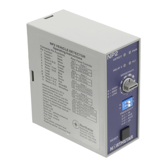
Features 10 selectable Sensitivities 4 selectable Frequencies Wrong voltage protection Output Timing – Extend & Delay Selectable Presence times Selectable Pulse lengths Separate Power, Detect and Fault Indicators Automatic Sensitivity Boost Available in: 240VAC, 120VAC, 24VAC, 24VDC or 12VDC Specifications. 1 3/8”... - Page 5 Rear Panel DIP Switch Selections Relay 1 Extend – switch 1 is for extending the detector output after the vehicle has left the loop. Switch 1 in the OFF position provides no extension. Switch 1 in the ON position provides a 5 second extension once the vehicle leaves the loop.
-
Page 6: Front Panel Selections
Front Panel Selections Sensitivity – controlled by front panel rotary switch. Setting Level dL/L 1.28% 0.64% 0.32% 0.16% 0.08% 0.06% 0.04% 0.02% 0.01% Set to position 5 initially and adjust to obtain detection of desired vehicles. Frequency – four separate settings controlled by front panel DIP switches. ... -
Page 7: Loop Installation
Loop Installation An inductive loop consists of a single length of wire, usually 12 to 18 gauge, wound in a square or rectangle shape often sawcut into the pavement. Both ends of this wire are brought back to the detector and connected to the ‘loop’ positions as designated on the unit. With the loop properly connected to the detector and the detector unit powered up, a field will be generated around the loop. -
Page 8: Helpful Tips
Detection height is a major factor in reliably detecting vehicles of interest. A good rule of thumb is that the small side of the loop will determine field height and provide 1/2 to 2/3rds that distance in detection height. Ex: 6’x4’ loop (4 foot side determines height) will have a field height of 24” to 32”. Ex: 10’x6’...