Advertisement
Quick Links
Advertisement

Related Manuals for Siemens Servo Screen 390


Summary of Contents for Siemens Servo Screen 390
- Page 1 Servo Screen 390 Service Manual E382 E394E 061 01 02 02...
- Page 2 Adequate service tools servicing. must also be used. As the Servo Screen 390 is a part of the Servo Worn-out batteries must be returned Ventilator system, there are also other to the place of purchase or to a place...
-
Page 3: Table Of Contents
Servo Screen 390 Contents Contents 1. Introduction ............... 2. Description of functions ........... 3. Disassembly and assembly ..........4. Service procedures ............5. Troubleshooting ..............6. Index .................. 7. Diagrams ................E382 E394E 061 01 02 02 Siemens-Elema AB... - Page 4 Notes Servo Screen 390 Notes E382 E394E 061 01 02 02 Siemens-Elema AB...
-
Page 5: Introduction
Servo Screen 390 1. Introduction 1. Introduction General ............ 6 Hardware overview ......... 7 Main sections ........8 Display section ........8 Computer section ....... 9 Firmware/software overview ....9 Firmware ..........9 Software ..........9 E382 E394E 061 01 02 02... - Page 6 1. Introduction Servo Screen 390 General Servo Screen 390 is a computer unit that reads information from a ventilator, makes calculations, and presents the information to the operator in a clear, logically organized manner. The primary purpose of Servo Screen 390 is to provide a central location for the display of all parameter information from the ventilator.
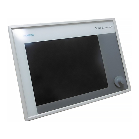
- Page 7 Servo Screen 390 1. Introduction Hardware overview Servo Screen 390 unit is a small, compact, ergonomically-designed computer unit. It is manufactured from materials suitable for use in a clinical environment and is designed specifically for integration with existing ventilator equipment.
- Page 8 • Display section (1) • Computer section (2) The support arm (3) is always used to mount the Servo Screen 390 on a ventilator cart or wall rail. Display section The anti-reflex coated front panel filter (4) protects the display (5) and makes it easy to keep the display clean.
- Page 9 Servo Screen 390 1. Introduction Computer section The two PC boards mounted in the computer section are: • Computer board (7), containing micro- processor, SS390-BIOS, internal memory and an interface for the software memory card. All connection ports except the power port are mounted on the computer board.
- Page 10 Servo Screen 390 1. Introduction Notes E382 E394E 061 01 02 02 Siemens-Elema AB...
-
Page 11: Description Of Functions
Servo Screen 390 2. Description of functions 2. Description of functions General ............ 12 Power supply........... 12 With Servo Ventilator 300/300A ..12 With Servo Ventilator 900C/E ..... 12 Adapter board .......... 13 General ..........13 Voltage distribution ......13 Signal adaption ........ - Page 12 7, “Diagrams” (on the The power supply is connected to the power inside of the back cover). inlet port PWR (P21) on Servo Screen 390. The internal power cable connects the power inlet port to the A at P18.
- Page 13 45°C (113°F), the fan is switched off. Replacing the fuse is described in chapter 4, “Service procedures”. Board identity The different voltage levels used in the Servo Screen 390 are regulated by and PC 1663 is equipped with a B OARD DENTITY distributed from this block.
- Page 14 WITCH General to the Servo Screen 390 on or off. This is the There are two different versions of the only device for turning the unit on or off. No other action is needed, e. g. when shutting...
- Page 15 The S contains the OFTWARE EMORY settings (e.g. battery replacement date), operating system and the Servo Screen 390 and the E RENDS VENT application software. Loading of the soft- Note – On PC 1835, T...
- Page 16 A monochrome electro-illuminating D ISPLAY (physically mounted as a part of the display used in this version of Servo Screen 390. section) is the only necessary device Display connection cables connect the available to a clinical user for operating the display to the block S application software.
-
Page 17: Disassembly And Assembly
Servo Screen 390 3. Disassembly and assembly Disassembly and assembly General ............ 18 Handling PC boards ......... 18 Separating the display section from the computer section ...... 19 Assembling the display section with the computer section ....... 19 Disassembling the display section ... 20 Pulse generator ........ - Page 18 The PC boards contain components that are assembly of some of the main parts of the highly sensitive to static electricity. Servo Screen 390. The drawings in the Those who come into contact with circuit Spare parts list are also very useful as a...
- Page 19 Servo Screen 390 3. Disassembly and assembly Separating the display section from the computer section • Remove the six screws (1). • Carefully separate the display section (2) from the computer section (3) as much as is needed to make the pulse generator...
- Page 20 3. Disassembly and assembly Servo Screen 390 Disassembling the display section Pulse generator • Separate the display section from the computer section as previously described. • Pull off the control knob (1) from the pulse generator shaft. • Remove the nut (2) and the washer (3) and lift off the pulse generator (4).
- Page 21 Servo Screen 390 3. Disassembly and assembly Front panel filter • Separate the display section from the computer section as previously described. • Pull off the control knob from the pulse generator shaft. • Remove the rubber sealing strips (1).
- Page 22 SRAM, will be erased when the battery is disconnected. Factory default settings will be used next time the Servo Screen 390 is turned on. • Remove the two nuts (2) and washers (3). • Remove the two screws (4) holding PC 1662/PC 1835.
- Page 23 Servo Screen 390 3. Disassembly and assembly • Remove the PC boards as previously described. • Remove the two nuts (1) and washers (2) holding the fan bracket and lift off the fan (3). Assembling the computer section The procedure for assembling the computer section is the reverse of the disassembly procedure described above.
- Page 24 3. Disassembly and assembly Servo Screen 390 Notes E382 E394E 061 01 02 02 Siemens-Elema AB...
-
Page 25: Service Procedures
Servo Screen 390 4. Service procedures Service procedures General ............ 26 Using the Service Menu ......27 Service access code ......27 Service information display ....28 Event list ..........28 Battery change-confirmation ....29 Using a keyboard ........30 Replacing the software memory card .. - Page 26 Servo Screen 390 General This chapter describes, step-by-step, some service procedures that may be necessary to perform on the Servo Screen 390. Some of these service procedures require dis- assembling the Servo Screen 390. If so, please see chapter 3, “Disassembly and assembly”...
- Page 27 Service Access Code The Service Access Code is intended only as a ”separator” between clinical use and technical use of the Servo Screen 390. It is not a secret or personal code and it cannot be changed. • Select the S...
- Page 28 The Service information display shows some technical data from the connected ventilator and from the Servo Screen 390. If the Servo Screen 390 is connected to a Servo Ventilator 300/300A, PROM versions in the SV 300/300A are shown on this display.
- Page 29 Servo Screen 390 4. Service procedures Battery change-confirmation The backup battery in the Servo Screen 390 must be replaced when the information ”Replace Servo Screen 390 battery” is displayed in the Message window (every three years). Replacement is described in the section “Replacing the battery”...
- Page 30 Servo Screen 390 Using a keyboard A standard AT keyboard can be connected to the Servo Screen 390. When the keyboard is connected, it is ready for use. No setting is needed. The keyboard can be used as a substitute for the control...
- Page 31 Servo Screen 390 4. Service procedures Replacing the software memory card • Make sure that the Servo Screen 390 is turned off. • Remove the protective cover (1). • Push the button (2) to release the software memory card from the memory card slot.
- Page 32 • Mount the new SS390-PROM into the socket. Make sure that it is correctly mounted and that no leg has been bent or broken. • Assemble the Servo Screen 390 as described in chapter 3, “Disassembly and assembly”. The SS390-PROM is now replaced.
- Page 33 • Remove the old SIMM chip (1) mounted on PC 1662/PC 1835. • Mount the new SIMM chip into the socket. • Assemble the Servo Screen 390 as described in chapter 3, “Disassembly and assembly”. The internal memory is now replaced.
- Page 34 When the information ”Replace Servo Screen 390 battery” is displayed in the Message window, the battery must be replaced. • Make sure that the Servo Screen 390 is turned off. • Loosen the two screws (1). • Carefully lift off the battery cover including battery (2), but do not remove the cable connector (3) from PC 1662/PC 1835.
- Page 35 3, “Disassembly and assembly”. • Remove the old fuse (1). • Insert a new fuse, 3.15 A fast. • Assemble the Servo Screen 390 as described in chapter 3, “Disassembly and assembly”. The fuse is now replaced. Perform a Functional check according to the instructions in the Operating Manual.
- Page 36 4. Service procedures Servo Screen 390 Adjusting the support arm The pre-tension in the joint as well as in the rail clamp can be adjusted if necessary: Joint • Loosen the screw (1). • Tighten or loosen the screw (2).
-
Page 37: Troubleshooting
Servo Screen 390 5. Troubleshooting Troubleshooting E382 E394E 061 01 02 02 Siemens-Elema AB... - Page 38 Malfunction Action • Check/replace the external power cable/ Servo Screen 390 will not start. The display connectors. is not illuminated and there is no start-up beep. • Check that the power supply source (ventilator or external power supply) works properly.
- Page 39 “ appears. OFTWARE ISSING The control knob does not work properly. • Operate the Servo Screen 390 with a connected keyboard: – If it works with the connected keyboard: 1. Replace the control knob. 2. If not the above, replace PC 1662/ PC 1835.
- Page 40 Servo Screen and SV 300/300A 300A. is connected to N82 on SV 300/300A. The Servo Screen 390 starts up, but does • Reset the memory in SV 300/300A-PC not display any information (e.g. curves or 1587. See SV 300/300A – Service Manual numerical values) from the SV 300/300A.
-
Page 41: Index
Servo Screen 390 6. Index Index E382 E394E 061 01 02 02 Siemens-Elema AB... - Page 42 6. Index Servo Screen 390 14 23 Adapter board PC 1663 13 22 Fan control AC Power Adapter 124 Firmware Front panel filter Fuse Battery Battery change-icon Battery replacement Handling PC boards Board identity Brightness control Bus interface Internal memory...
- Page 43 Servo Screen 390 6. Index Service access code Service information display Service menu Signal adaption Software Software memory card Software mem. card interface SRAM SS390-BIOS SS390-FLASH SS390-PROM Support arm Support arm joint Support arm rail clamp VENT port Video memory...
- Page 44 Servo Screen 390 6. Index Notes E382 E394E 061 01 02 02 Siemens-Elema AB...
-
Page 45: Diagrams
Servo Screen 390 7. Diagrams Diagrams E382 E394E 061 01 02 02 Siemens-Elema AB... - Page 46 7. Diagrams Servo Screen 390 KBD – N6 Keyboard port for connection of a keyboard. DIN 41524, female, 5 pole. KEY_CLK KEY_DATA +5 V – A* CHASSIS_GND PRINTER – N7 Printer port for connection of a printer. D-Sub, female, 25 pole.
- Page 47 Servo Screen 390 7. Diagrams VENT – P9 Serial communication port for communi- cation with the Servo Ventilator. D-Sub, male, 9 pole. DCD_2A DSR_2A RXD_2A RTS_2A TXD_2A CTS_2A Communication cable between DTR_2A RI_2A SS 390 and SV 300/300A A* CHASSIS_GND...
- Page 48 PULSE BRIGHT- SS390-BIOS FUNCTION MEMORY GENERATOR NESS MONITORING INTERFACE CONTROL BATTERY CONNECTION PORTS: VENT PRINTER 24V POWER CABLE If connected If connected to SV 300/300A to SV 900C/E AC POWER From ADAPTER Servo Screen 390 – Block diagram SV 300/300A...
- Page 49 E382 E394E 061 01 02 02 Order No.: 63 14 251 E394E © Siemens-Elema AB, Electromedical Systems Division, 1995-2000. All rights reserved. No part of this Printed in Sweden publication may be reproduced, stored in a retrieval system, or transmitted in any form or by any means,...