YASKAWA MOTOMAN YRC1000 Instructions Manual
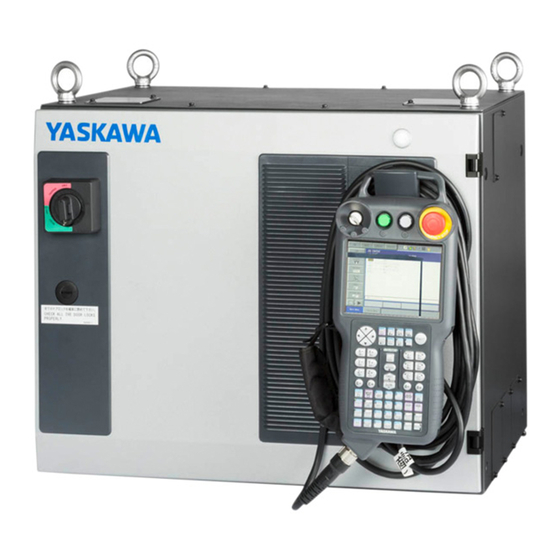
Robot controller
Hide thumbs
Also See for MOTOMAN YRC1000:
- Instructions manual (493 pages) ,
- Operator's manual (198 pages) ,
- Startup manual (87 pages)
Advertisement
Quick Links
Advertisement

Related Manuals for YASKAWA MOTOMAN YRC1000


Summary of Contents for YASKAWA MOTOMAN YRC1000
- Page 1 ROBOTICS Instructions Robot controller User manual...
- Page 2 This documentation – also in part – may be reproduced or made available to third parties only with the express approval of YASKAWA Europe GmbH „Robotics Division“. We have checked the content of this publication for compliance with the hardware described.
- Page 3 YASKAWA manual list........
- Page 4 Table of contents 5.3.4 User I/O cable connection ......... . 53 Turning ON and OFF the power supply .
- Page 5 Table of contents 9.5.5 Output of the work home position signal ......127 Interference area.
- Page 6 Table of contents 9.23 JOB monitor function ........... 237 9.24 Robot monitor function .
- Page 7 Table of contents 10.1.2 Storage medium ..........334 10.2 Backup by CMOS.BIN .
- Page 8 Table of contents 15.5.1 Inverter unit configuration ......... . 408 15.5.2 Inverter .
- Page 9 Indicates important background information and application advice. Frequently used terms The YASKAWA robot is a product of YASKAWA Electric Corporation, and is provided by default with the robot control, the programming pendant and robot cable. The terms are designated as follows in this manual:...
- Page 10 For optimal use of our products, we recommend our customers to take part in a training session at the YASKAWA Academy. For more detailed information on the training programs, please visit www.yaskawa.eu.com or directly get in touch with your YASKAWA branch office.
- Page 11 General Improper use Any use that deviates from the intended use shall be regarded as impermissible misuse. This includes: • Transport of people and animals • Use as ascending aid. • Use outside the permissible operating limits. • Use in environments with risk of explosion (except for ATEX-approved robots). •...
- Page 12 If your copy of the operating and maintenance instructions is damaged or lost, please contact the local YASKAWA branch office to order a new copy. The official branch offices are listed on the last page. Please mention the manual number in your order.
- Page 13 General • means that the cursor is moved to the object item and the [SELECT] key is pressed. • that the item is directly selected by touching the screen. Registered Trademark The names of companies and/or products used in this manual are trademarks. The indications of ®...
- Page 14 General Manufacturer Address: YASKAWA ELECTRIC CORPORATION 2-1 KUROSAKISHIROISHI YAHATANISHI-KU KITAKYUSHU JAPAN Address: YASKAWA NORTIC AB P.O. Box 504 Verkstadsgatan 2 385 25 Torsås Sweden Authorized representative Address: YASKAWA Europe GmbH Robotics Division Yaskawastr. 1 85391 Allershausen Germany...
- Page 15 Safety Safety Programming Pendant Emergency stop button WARNING! Danger of death or injury from crushing If the emergency stop button is not working properly, the robot cannot be stopped in the event of an emergency. The robot should not be used if the emergency stop button is not working. ...
- Page 16 Safety WARNING! Danger of death or injury from crushing Before you release the emergency stop button (see Fig. 2-3: "Releasing the emergency stop button by rotating it"), note the following Make sure there is no one within the maximum operating range of the robot. ...
- Page 17 For optimal use of our products, we recommend our customers to take part in a training session at the YASKAWA Academy. For more detailed information on the training programme, please visit www.yaskawa.eu.com or directly get in touch with your YASKAWA...
- Page 18 Safety YASKAWA manual list It is important to have all the manuals on the YASKAWA control or robot available and to know their contents. Please make sure you have all these manuals. If you are missing any manual, please contact the local YASKAWA branch office.
- Page 19 Safety Personal protection The entire working area of the robot is potentially dangerous. The following staff must work with appropriate preparation and subject to the maxim "Safety First" to ensure the safety of all. • Safety management • Assembly staff •...
- Page 20 Safety MOTOMAN Safety The followings are safety functions of robot controller. • Emergency stop SW input (programming pendant) • Enable SW input (programming pendant) • Safeguarding interlock signal input (safety plug) • External emergency stop SW input • External enable SW input •...
- Page 21 Safety Safety during installation and wiring CAUTION! Personal injury and damage from improper connections and unforeseen movements Operators and other personnel may stumble on exposed wiring or piping. Damaged cables may cause unexpected robot movements. Familiarize yourself with the wiring diagram and take notice thereof when establishing the connections.
- Page 22 Safety WARNING! Injury and material damage due to unforeseen movements. When planning installation, draw up easy-to-observe guidelines to ensure safety. Take safety aspects into consideration when planning the installation. Observe the following when installing the robot: Select an area such as that described below to install the robot ...
- Page 23 Safety 2.5.1 Using a crane CAUTION! Danger of injury and material damage from improper means of transport Crane, forklifts or slings may only be operated by authorised personnel. When lifting the robot controller, please check the following: As a rule, handling of robot controller must be performed using a crane with wire rope threaded through attached eyebolts.
- Page 24 Safety Fig. 2-5: Space for maintenance Door At least 1000 mm Robot control maintenance area All dimensions in mm 2.5.3 Fixing the robot controller CAUTION! Danger of injury and material damage in case of non-compliance with protective measures For safe operations, the following points must be observed. ...
- Page 25 Safety • When the power supplies of the robot and the YRC1000are turned ON at start-up, be sure to confirm the following: – Safety protection devices such as the emergency stop circuit, the safety plug, etc. operate normally. – Each axis operates normally in the TEACH mode. –...
- Page 26 Safety WARNING! Danger of injury and material damage caused by unforeseen movements of the robot If possible, teach JOBs from outside the robot’s maximum work area. Take the following precautions when performing teaching operations within the robot’s operating range: Always view the robot from the front. ...
- Page 27 Supply Supply Checking the scope of delivery The standard delivery includes the following items: Scope of delivery Programming pendant Robot controller Robot Cable The present assembly instruc- tions READ ONLY MEMORY...
- Page 28 Supply Product confirmation Main module options • Socket with angled connector plate (height = 250 mm) • Cabinet with or without angled connector plate, standard height (height = 499 mm). • Cabinet with angled connector plate, double height (height = 499 mm).
- Page 29 Supply Additionals options • Drawer for socket • Mounting plate for I/O unit in socket. • Swing frame for standard cabinet (height = 499 mm). • Swing frame (high) for double height cabinet (height = 989 mm)
- Page 30 Supply • Hood for CEE-connector • Covers...
- Page 31 Supply Position type plate NOTICE Please contact the local YASKAWA branch office if the serial numbers do not match the information on the delivery note. Verify whether the serial number of the robot, the robot controller and the programming pendant with the delivery.
- Page 32 Installation Installation Transportation CAUTION! Personal injury or damage to property The system consists of precision components. If this precaution is not taken, performance may be impaired. A crane or forklift may only be operated by authorized personnel. The same applies to the use of slings.
- Page 33 Installation 4.1.1.2 Using a forklift If the robot controller is to be transported by forklift, it must be secured with safety belts, as shown in the figure "Transport by forklift" below. Make sure that the forklift and the transportation route have sufficient bearing capacity. Always take due care when transporting the robot controller.
- Page 34 Installation 4.1.1.3 Using a lifting truck CAUTION! Personal injury and material damage during transport Avoid jarring, dropping, or hitting the controller during handling. Excessive vibration or impacting the robot controller may adversely affect the performance of the robot controller. ...
- Page 35 Installation 4.1.1.4 Transporting robot controller and cabinet for external axis External axis cabinet may be mounted to the base cabinet in number of ways. If placed side by side, the control cabinets are fastened with M12 bolts. However, this fixation will not withstand lifting.
- Page 36 Installation 4.2.1 Protection measures DANGER! Personal injury and material damage The robot system must not be operated without protective devices. Starting up without appropriate protective measures can lead to death of people, serious bodily harm or material damage. Implement the following protection measures ...
- Page 37 Installation 4.2.2 Ambient conditions and installation location A robot controller may only be installed in the following ambient conditions: • Air humidity: 10% to 90% relative humidity (without condensation). • Must be as dust-free, clean and dry as possible. • Free of corrosive or explosive gases or liquids •...
- Page 38 Installation 4.2.4 Installation options WARNING! Personal injury and damage to property The following precautions must be taken. Keep the robot controller lifted by the crane until the robot controller is stacked and fixed securely. It is possible to stack the YRC1000 controllers. Follow the procedures below when stacking the YRC1000 controllers.
- Page 39 Installation 3. After stacking the controllers, remove the grommets inside (A-A section “a” part) of the upper controller. Install the M12 x 35 bolts, spring washers and washers for temporally. 2 x Grommet "a" enlarged view Robot controller (upper) Robot controller (lower) M12 x 35 Spring washer Washer...
- Page 40 Installation 5. After stacking the controllers, remove the grommets inside (A-A section “b” part) of the upper controller. Install the M12 x 35 screws, spring washers and washers for temporally. 2 x Grommet "a" enlarged view Robot controller (upper) Robot controller (lower) M12 x 35 Spring washer Washer...
- Page 41 Installation 4.2.5 Configurations The controller cabinet YRC1000 is always placed on top. The socket , if used, is always placed at the bottom to position cables and connectors the controller cabinet YRC1000 at correct height in relation to the robot. 4.2.5.1 Single robot system Master controller...
- Page 42 Installation 4.2.5.3 Triple robot system Master controller Slave controller 1 Slave controller 2 Optional cabinet Master controller Slave controller 1 Optional cabinet , double height Slave controller 2 Optional cabinet , double height...
- Page 43 Connection Connection DANGER! Death from electrical shock, risk of fire due to short circuit. Wiring must be performed by authorized or certified personnel. Failure to ground equipment may result in fire or electric shock. Capacitors inside the robot controller store electricity after power is turned OFF. Exercise caution whenever handling circuit boards.
- Page 44 If the robot controller for European standards is used in Japan, an electric shock may result from increase in leakage current due to differences in power supply condition. The robot controller must be grounded. NOTICE If the supply voltage differs, please contact the local YASKAWA branch office.
- Page 45 Connection 5.2.1 3-phase power supply The three-phase power supply consists of 3-phase 380-440VAC 50/60Hz (neutral earthing). YRC1000 type Power supply For Japan ERAR-1000-xxxxxxx-A0x 3-phase 200 to 240 VAC (+10% to -15%) at 50/60 Hz (±2%) For Asia ERAR-1000-xxxxxxx-A1x 3-phase 380 to 440 VAC (+10% to -15%) at 50/60 Hz (±2%) (neutral earthing) For Europe ERAR-1000-xxxxxxx-E1x...
- Page 46 Connection 5.2.2 Leakage breaker installation When connecting the leakage breaker to the controller power supply wiring, use a leakage breaker which can handle high frequencies from the YRC1000 inverter. Leakage breakers which cannot handle high frequencies may malfunction. Even with a leakage breaker installed, there is still a possibility of some high frequency current leakage from the YRC1000.
- Page 47 The power capacity is changed when using an external axis. For details of the power capacity with an external axis, please contact to your YASKAWA representative or check the rated value name plate on the controller.
- Page 48 Connection Connection methods Fig. 5-1: Connecting the robot system 5.3.1 Connection to primary power supply There are 3 ways to connect to power supply Standard connection: Connection is made directly to the main switch, when in the cable goes through an opening at the back of the cabinet at the upper right corner.
- Page 49 Connection Before you turn on the main power supply, first connect all other cables which are needed such as the cables between robot and robot controller. NOTICE The grounding inside the robot controller is factory assembled (maximum grounding resistance of 0.1 ).
- Page 50 Connection 5. Connect a ground wire to reduce noise and prevent electric shock. Connect the ground wire to the ground terminal (screw) which is on the upper left side of YRC1000. Grounding terminal (M6 screws) Grounding wire Perform grounding in accordance with all relevant local and national electrical codes. The size of ground wire must the same as listed on table Tab.
- Page 51 Connection 8. Close the YRC1000 door.
- Page 52 Connection 5.3.2 Connection of the robot controller DANGER due to electric current! Danger to life due to electric shock! Danger to life and serious injuries caused by high voltage. Before carrying out the wiring, ensure that the door of the robot controller is in principle closed.
- Page 53 Connection 5.3.3 Connecting the programming pendant Connect the programming pendant cable to the connection (X81) (see diagram "Connecting the programming pendant"). Fig. 5-4: Connection programming pendant Alignment marks 5.3.4 User I/O cable connection User can choose one I/O cable connection method out of following three ways. Connect user I/O signal to I/O ter- User connects general-purpose I/O signal through minal blocks (Material-No.
- Page 54 Connection 1. Remove covering plates from I/O cable openings on the back side panel of the controller. Reserved for Conveyor in the low budget version 24 DC and the bus connection in the low budget version Cable set B in the low budget version Cable set A in the low budget version 2.
- Page 55 Connection 4. Draw the user system external signal cable and general-purpose I/O signal cable from the cable openings to the front part of the controller along its right side. Run the cabel through the front side of the robot controller. 5.
- Page 56 Connection 7. Run the general-purpose I/O signal cables through the general-purpose I/O board (JANCD-AIO0□-E) as shown by the red line in the figure below. NOTICE For the details of the connection, refer to “Wiring Procedure of the Terminal Block” in chapter 15.16 "General purpose I/O board"”...
- Page 57 Turning ON and OFF the power supply Turning ON and OFF the power supply Turning ON the main power supply WARNING! Risk of injury due to crushing hazard. The emergency stop button is located at the top on the right side of the programming pendant.
- Page 58 Turning ON and OFF the power supply 6.1.2 When initial diagnosis are complete When the main power supply is turned off the robot controller stores all data that has been set including: • operating mode • called JOB (active JOB, when the robot controller is in PLAY mode, edit JOB when the robot controller is in TEACH mode) as well as the cursor position in the JOB.
- Page 59 Turning ON and OFF the power supply Turning ON the SERVO power 6.2.1 During PLAY MODE NOTICE If the safety circuit is interrupted, the SERVO power cannot be turned on. • When the safety circuit is closed, press [SERVO ON READY] on the programming pendant to turn on the SERVO power.
- Page 60 Turning ON and OFF the power supply Servo On Release OFF Squeezed tightly OFF Squeezed ON NOTICE The SERVO power, which was activated by the enable switch, is interrupted when an emergency stop is initiated. To turn the SERVO power back on follow the previously listed instructions.
- Page 61 Turning ON and OFF the power supply Turning OFF the power supply 6.3.1 Turning OFF the SERVO power (emergency stop) The robot cannot be operated when the emergency stop button is pressed and the SERVO power supply is turned off. •...
- Page 62 Turning ON and OFF the power supply Besides the safety signals, there are three stop categories to stop the robot: • Stop category 0 The immediate disconnection of power to the SERVO motor triggers the stop. After the power is disconnected, the brake is released causing the robot and the external axis to decelerate until they finally stop.
- Page 63 Test of program operation Test of program operation Movement of the axes WARNING! Danger of death or injury from crushing hazard if anyone enters the working area of the robot during operation or any problems occur, always press the emergency stop button immediately. The emergency stop button is located on the programming pendant.
- Page 64 Test of program operation Rotates main body Rotates upper arm Moves lower arm forward / backward Moves wrist up / down Moves upper arm up / down Rotates wrist Rotates lower arm...
- Page 65 Release the brake of only one axis at a time. Pay attention to your surroundings. In case of purchase, please contact your local YASKAWA branch office. The official branch offices are listed on the last page.
- Page 66 Security system Security system Protection through security mode settings The robot controller modes setting are protected by a security system. The system allows operation and modification of settings according to operator clearance. Be sure operators have the correct level of training for each level to which they are granted access.
- Page 67 9 or more and 16 or less characters with number(s) and symbol(s). (Significant numbers and symbols: ”0 to 9”, “-”, “.”. ) Operating the ONE TIME MANAGE MODE requires to enter the security code, which is issued by YASKAWA sales representative. Security mode Explanation...
- Page 68 Security system Main menu Sub menu Permitted security mode DISPLAY EDIT Operation Edit SELECT JOB Operation Operation CREATE NEW JOB Edit Edit MASTER JOB Operation Edit JOB CAPACITY Operation RES. START (JOB) Edit Edit RES. STATUS Operation CYCLE Operation Operation TRASH JOB LIST Edit Edit...
- Page 69 Security system Main menu Sub menu Permitted security mode DISPLAY EDIT IN/OUT EXTERNAL INPUT Operation Edit EXTERNAL OUTPUT Operation Edit GENERAL PURPOSE INPUT Operation Operation GENERALL PURPOSE OUT- Operation Operation SYSTEM INPUT Operation SYSTEM OUTPUT Operation Operation CPRIN Operation REGISTER Operation Management AUXILIARY RELAY...
- Page 70 Security system Main menu Sub menu Permitted security mode DISPLAY EDIT ROBOT CURRENT POSITION Operation COMMAND POSITION Operation SERVO MONITOR Management WORK HOME POS Operation Edit SECOND HOME POS Operation Edit DROP AMOUNT Management Management POWER ON/OFF POS Operation TOOL Edit Edit INTERFERENCE...
- Page 71 Security system Main menu Sub menu Permitted security mode DISPLAY EDIT PARAMETER S1CxG Management Management Management Management Management Management Management Management Management Management Management Management Management Management Management Management Management Management Management Management Management Management Management Management Management Management Management Management Management Management...
- Page 72 Security system Main menu Sub menu Permitted security mode DISPLAY EDIT SETUP TEACHING COND. Edit Edit OPERATE COND. Management Management OPERATE ENABLE Management Management FUNCTION ENABLE Management Management JOG COND. Management Management PLAYBACK COND. Management Management FUNCTION COND. Management Management DISPLY COLOR COND.
- Page 73 Security system Main menu Sub menu Permitted security mode DISPLAY EDIT ARC WELDING ARC START COND. Operation Edit ARC END COND. Operation Edit ARC AUX COND. Operation Edit POWER SOURCE COND. Operation Edit ARC WELD DIAG. Operation Edit WEAVING Operation Edit ARC MONITOR Operation...
- Page 74 Security system Changing the security mode: 1. Select {SYSTEM INFO} from the main menu. The sub menu appears. NOTICE The icons for the main menu, like the arc welding system, depend on the system used. 2. Select {SECURITY}. The selection window for the security mode appears. 3.
- Page 75 “ONE TIME MANAGE MODE”. 2. Select “ONE TIME MANAGE MODE”. A character string input keypad is displayed. Input the one time security code, which is issued by YASKAWA sales representative. If the password is correct, the security mode will be changed.
- Page 76 Security system User ID User ID is requested when the editing mode, management mode or safety mode is operated. The user ID should be 4 or more and 16 or less characters with number(s) and symbol(s) for the editing mode and the management mode. As for the safety mode, it should be 9 or more and 16 or less characters with number(s) and symbol(s).
- Page 77 Security system 3. Select the desired ID. The character input line appears, and a message “Input ID no. (4 or more digits)” appears (As for the safety mode, 9 or more digits). 4. Input the current ID and press [ENTER].. When the correct user ID is entered, a new ID is requested to be input.
- Page 78 Security system 3. Select {VERSION}. VERSION window appears. 4. Select {UTILITY} under the pull-down menu. “SD Card ID” appears. 5. Select “SD Card ID”. SD Card ID dialog of the main CPU appears.
- Page 79 In a system with two or more Robots, the home position of all the Robots must be calibrated before starting teaching or playback. For more information, see also system setup in the manual or contact your YASKAWA branch.
- Page 80 System Setup 9.1.1 Registering all axes at the time 1. Select {ROBOT} from the main menu. 2. Select {HOME POSITION}. The <HOME POSITIONING> window appears. 3. Select {DISPLAY} under the menu, or select “PAGE” to display the selection window for the control group, or press [PAGE].
- Page 81 System Setup 6. Select {SELECT ALL AXES}. A confirmation dialog box is displayed. 7. Select {YES}. Displayed position data of all axes are registered as home position. When {NO} is selected, the registration will be canceled. 9.1.2 Registering individual axes 1.
- Page 82 System Setup 9.1.3 Changing the absolute data To change the absolute data of the axis when home position calibration is completed, perform the following: 1. Select {ROBOT} from the main menu. 2. Select {HOME POSITION}. 3. Select the desired control group. Perform steps 3 and 4 which have been described in chapter “Registering All Axes at One Time”...
- Page 83 System Setup 4. Select {CLEAR ALL DATA}. The confirmation dialog box appears. 5. Select {YES}. The all absolute data are cleared. When {NO} is selected, the registration will be canceled.
- Page 84 System Setup 9.1.5 Home position posture of robot NOTICE The home position posture of each robot differs depending on its model. Refer to the INSTRUCTIONS for the robot corresponding to its model. The home position posture of a commonly used 6-axis vertically-articulated robot is shown below.
- Page 85 System Setup Setting the second home position (check point) 9.2.1 Purpose of position check operation If the absolute number of rotation detected at power supply ON does not match the data stored in the absolute encoder the last time the power supply was turned off, alarm 4107 “OUT OF RANGE (ABSO DATA)”...
- Page 86 System Setup 1. Position check After the “OUT OF RANGE (ABSO DATA)” alarm occurs, move to the second home position using the axis keys and perform the position confirmation. For performing the position confirmation, refer to chapter “Procedure after the Alarm”. Playback and test runs will not function unless “CONFIRM POSITION”...
- Page 87 System Setup 9.2.2 Procedure for the second home position setting Robot Controller Powe supply unit JZRCR-YPU51-1 CN602 CN601 Emergency stop button CN608 CN610 3,4FU CN612 CN611 1,2FU CN606 CN605 Machine safety I/O CN603 Universal I/O board CN604 logic board JANCD-YIO21-E JARCR-YPC21-1 CN607 PPESP,PPDSW...
- Page 88 System Setup If the „OUT OF RANGE (ABSO DATA)“ alarm occurs, • Reset the alarm. • the SERVO power ON. Then confirm the second home position. After the confirmation, if the PG system is found to be the cause of the alarm, perform the necessary operation, such as replacing the PG system, etc.
- Page 89 System Setup 6. Select {CONFIRM POSITION}. A message „Home position checked“ appears. Pulse data of the second home position and current pulse data should be compared. Automatic mode can be done if compared error is in allowed range. If the error is beyond the allowed range, the alarm occurs again.
- Page 90 System Setup Tool data setting 9.3.1 Number of tool files There are 64 tool files that are 0 to 63 numbered. Every file is a tool file. TOOL FILE 0 TOOL FILE XX NOTICE Tool File Extension Function Normally, one robot uses one kind of tool file. The tool file extension function can change many tool files to be used by one robot.
- Page 91 System Setup 1. Select {ROBOT} from the main menu. – The submenu appears. 2. Select {TOOL}. 1) Move the cursor to the desired tool number, and press {SELECT} in the "tool list" window. The tool coordinate window of the selected number appears. –...
- Page 92 System Setup 6. Press [ENTER]. – The coordinates are registered. <Setting example> Tool A Tool B Tool C 260 mm 260 mm 260 mm 145 mm In the case of tool A, B In the case of tool C...
- Page 93 System Setup 9.3.3 Registering the posture data The tool position data is angle data that shows the relationship between the flange coordinates and the tool coordinates. The angle by which the flange coordinates are turned in order to match the tool coordinates can be entered.
- Page 94 System Setup 6. Press [ENTER]. The angle of rotation of Rz is registered. Register the angles of Ry, Rx in the same way. Ry must be the entered angle of rotation around X' of the flange coordinates. Ry = 90 Rx must be the entered angle of rotation around X' of the flange coordinates.
- Page 95 System Setup 9.3.4 Setting the tool load information WARNING! Injuries and damage in the event of a collision between the tool and positioner Changes to the tool load data can lead to minor changes to the robot path. To prevent injuries or damage as a result of a collision between the tool and positioner, check the path before the execution of a JOB.
- Page 96 System Setup 9.3.5 Tool calibration To ensure that the robot can execute movements such as linear and circular movements correctly, the exact dimensions of tool such as welding torches and welding guns must be registered. In addition, the position of the TCP must be set. The tool calibration permits these dimensions to be registered easily and precisely.
- Page 97 System Setup 9.3.5.2 Teaching of calibration point Defining coordinates To calibrate the coordinates, five different positions (TC1 to 5) have to be taught with the TCP as the reference point. The tool dimensions are calculated automatically on the basis of these five points. Every position must be arbitrary.
- Page 98 System Setup In calibration with S2C432=2, teach TC1 with the Z-axis of the desired tool coordinates vertically downwards in the direction of the floor. Then teach the other calibration teach points (TC2~TC5) with all tool points in the tool point of TC1 (see the figure below). If teaching is not possible at any point due to the peripheral devices, etc.
- Page 99 System Setup 4. Select {UTILITY} from the main menu. – The pull-down menu appears. 5. Select {CALIBRATION}. – The TOOL CALIBRATION window appears. 6. Select the robot. 1) Select the robot to be calibrated. (Do not select the robot if the robot has already been selected or if there is only one robot.) 2) Select "**”...
- Page 100 System Setup 9. Press [MODIFY] and [ENTER]. – The taught position is registered. Repeat steps 7 to 9 to teach TC1 to TC5. "" means that teach-in is completed, and "" means that teach-in is not completed. – To check the taught positions, open the required window for TC1 to TC5 and press [FWD].
- Page 101 System Setup 9.3.5.3 Clearing calibration data Before calibrating a new tool, delete the robot and calibration data. 1. Select {DATA} from the pull-down menu. – The pull-down menu appears. 2. Select {CLEAR DATA}. – The confirmation dialog box appears. 3. Select {YES}. –...
- Page 102 System Setup 9.3.5.4 Checking the TCP Once you have registered the tool file, check whether the TCP has been registered correctly. Carry out a TCP-related operating step (see the description below) in one of the coordinate systems. However, do not use the joint coordinate system. Tool center point 1.
- Page 103 System Setup 9.3.6 Automatic Measurement of the Tool Load and the center of gravity This function allows the user to register the tool load and the position of the tool's centre of gravity. The tool load and centre of gravity are measured and registered in a tool file. NOTICE This function can be used if the robot is installed on a level surface.
- Page 104 System Setup 2. Select {TOOL}. The tool list window appears. The tool list window only opens if the file extension function is valid. IIf the tool extension function is invalid, the tool coordinate window is opened.
- Page 105 System Setup 3. Select the desired tool number. – Move the cursor to the desired tool number in the tool list window, and press [SELECT]. – The tool coordinate window of the selected number appears. – In the tool coordinate window, the number can be changed by pressing the page button or by selecting {PAGE}.
- Page 106 System Setup 6. Press the [GO BACK PAGE] button. In a system with multiple robots, use [GO BACK PAGE] to switch the group to be controlled. 7. Press [FWD]. – Press [FWD] once. The robot returns to its home position (horizontal to the U-, B- and R-axes).
- Page 107 System Setup NOTICE The moment of inertia at the center of gravity does not need to be measured when this data is small enough for the moment of inertia calculated from weight and the center of gravity position. However, the measurement is required when the moment of inertia of the tool is large (as a rough guide, the tool is considered to be large when the tool size is about more than 2-times the distance between the flange and the center of gravity).
- Page 108 System Setup 2. Press [FWD] again. – Press [FWD] again, and measurement of B-axis 1 and B-axis 2 starts. The robot moves in the order listed below. Once measurement is completed, “○” changes to “●”. 1) Measurement of the B-axis 1: B-axis home position +30 degrees → -30 degrees 2) Move to the measurement position of B-axis 2 3) Measurement of the B-axis 2: B-axis home position +30 degrees →...
- Page 109 System Setup 4. Press [FWD] again. – Press [FWD] again, and measurement of T-axis starts. 1) Measurement of the T-axis: T-axis home position +30 degrees → -30 degrees When the measurement is completed, the measured data appears on the screen NOTICE ...
- Page 110 System Setup ARM Control ARM Control, a control system originally developed by Yaskawa, achieves an enhanced robot motion performance such as improved path accuracy or reduced cycle time. The moment of inertia and the gravity moment etc. of each axis are calculated by the ARM control function, and robot controller controls robot motion according to the result.
- Page 111 System Setup 9.4.1.1 Robot setup condition Meet the following robot setting condition to enable the ARM control system. • Robot installation angle • S head load-carrying capacity • U arm load-carrying capacity 9.4.1.2 Robot installation angle The robot installation angle relative to the floor is set in ANGLE REL. TO GROUND to calculate the centre of gravity for each robot axis.
- Page 112 Only the angle of rotation around the Y-axis of the robot coordinates can be set in the robot installation angle. Contact your YASKAWA office if the Y-axis of the robot coordinates is to be inclined relative to the floor. 9.4.1.3...
- Page 113 System Setup 9.4.1.4 U-arm payload Set the weight and centre of gravity approximately when equipment such as motors are installed on the U arm. A default value is set at the factory. Specify 0 for the weight if no equipment is installed on the U arm. •...
- Page 114 System Setup 2. Select {ARM CONTROL}. – The ARM CONTROL window appears. 3. Press [GO BACK PAGE] or select {PAGE}. – Select the desired control group if there are two or more group axes. 4. Select the desired point. 5. Enter the value and press [ENTER].
- Page 115 System Setup 9.4.2 Tool load information setting WARNING! Personal injury or equipment damage by collision between a tool and a fixture Perform the settings of the tool load information after installing the tool and before teaching a JOB. If the tool load information is modified at another time, check the path of the robots operation for each JOB which uses the corresponding tool file.
- Page 116 System Setup 9.4.2.1 How to calculate tool load information • Weight: W (unit: kg) The total weight of the installed tool is set. It is not necessary to set the correct value. However, it is recommended to set a value that is somewhat higher than the actual load (round the value up between 0.5 and 1 kg for small and medium-sized robots and between 1 and 5 kg for larger robots).
- Page 117 System Setup <Example 1> In the welding gun example below, the center of gravity is set in the flange coordinates. It is assumed that the center of gravity is at a slight angle from the head to the center point. It is not necessary to set the moment of inertia at the center of gravity, since the welding gun is not too large.
- Page 118 System Setup <Example 2> The moment of inertia must be set at the center of gravity if the total size of the tool and workpiece is large compared to the distance between the flange and the center of gravity. Calculate the moment of inertia at the center of gravity roughly on the basis of the formula (see the moment of inertia for hexahedron and cylinder above).
- Page 119 System Setup 1. Split the tool up into individual parts because the weight and center of gravity can be determined approximately. It is not necessary to split it up precisely. The tool is used to deal with unfinished parts. 2. Calculate the weight and center of gravity of each part on the flange coordinates. This can be an approximate value.
- Page 120 System Setup <Example 3> If there are two or more heavy loads such as double welding guns (see the figure below): 1. Set the center of gravity if the center of gravity for the whole tool has been determined approximately. Set the moment of inertia at the center of gravity that has been calculated through approximation of the whole tool in the shape of a hexahedron or cylinder (this setting is sufficient as a rule).
- Page 121 System Setup * In this case, the moment of inertia (Icxi, Icyi, Iczi) of the welding gun is not taken into account, since each gun is smaller than the entire tool. <Setting> 10,000 kg Xg : 100,000 mm Yg : -83,333 mm Zg : 60,000 mm...
- Page 122 System Setup 4. Select the point to be registered and enter the value. – You can move the cursor around in the window. – You make the entry in the menu when the cursor is on the point to be registered and you press [SELECT].
- Page 123 System Setup NOTICE • If the data setting is not made, the tool load data is not set correctly in the following cases: – When the weight (W) is "0". – When the center of gravity for Xg, Yg and Zg is "0". In these cases, the robot is controlled by means of the default settings (which different depending on the robot model) made before shipping.
- Page 124 System Setup Work home position 9.5.1 What is the work home position? The work home position is a reference point for robot operations. It prevents interference with peripheral device by ensuring that the robot is always within a set range as a precondition for operations such as starting the line.
- Page 125 System Setup 3. Press the [GO BACK PAGE] button. – If there are two or more robots in the system, use [GO BACK PAGE] to change the control group, or click {PAGE} to select the desired control group.
- Page 126 System Setup 9.5.3 Changing and registering the work home position 1. Press the axis button in the home position display. – Move the robot to the new work home position. 2. Press [MODIFY] and [ENTER]. – The new work home position is set. NOTICE If the work home position is changed, the cube interference area is automatically set as cube 64 to 57 in the base coordinate system.
- Page 127 System Setup 9.5.4 Returning to the work home position • In TEACH mode Press [FWD] in the home position display. – The robot is moved to the new work home position. The speed at which it moves is the speed selected for manual operation. •...
- Page 128 System Setup Interference area The interference area is a function that prevents interference between multiple robots or the robot and peripheral device. The areas can be set up to 64 areas. There are two types of interference areas, as follows: •...
- Page 129 System Setup • Cubic interference: Specified output signal = ON • Outside of cubic area: Specified output signal = OFF TCP is located outside the cube • Cubic interference: Specified output signal = OFF • Outside of cubic area: Specified output signal = ON Cubic Interference Area...
- Page 130 System Setup 9.6.2 Cube setting method A cube interference area can be set in three ways as follows: 1. Enter the maximum and minimum values for the cube coordinates. Z-axis Minimum value X-axis Y-axis Cube interference area axis Maximum value 2.
- Page 131 System Setup 1. Select {ROBOT} from the main menu. 2. Select {INTERFERENCE}. – The "INTERFERENCE AREA" window appears. 3. Select the desired cube number. – Select the cube number with [PAGE], or enter the number directly. – Select {PAGE} when entering the cube number using the numeric keys to enter the signal number.
- Page 132 System Setup 5. Select "CONTROL GROUP". – A selection dialog box appears. Select the desired control group. 6. Select "REF COORDINATES". 1) A selection dialog box appears. 2) Select the desired coordinate. 3) If you select the user coordinates, the number input line appears. Enter the user coordinate number and press [ENTER].
- Page 133 System Setup 8. Select ALARM OUTPUT. – Each time [SELECT] is pressed, “OFF” and “ON” are displayed alternately. – When selecting “ON” and if the robots TCP approaches inside the pre-defined interference area, the following alarm occurs and the robot stops immediately. AL4902: CUB.
- Page 134 System Setup 2. Select „MAX/MIN“. 3. Press [MODIFY]. – The message TEACH MAX/MIN POSITION appears. 4. Move the cursor to „<MAX>“ or „<MIN>“. – Move the cursor to „<MAX>“ if you want to change the maximum value and „<MIN>“ to change the minimum value.
- Page 135 System Setup 2. Select „CENTER POS“. 3. Enter the length of the cube and press [ENTER]. – The length is set. 4. Press [MODIFY]. – The message „MOVE TO CENTER POINT AND TEACH“ is displayed. The cursor moves to either "<MIN>" or "<MAX>" this time. 5.
- Page 136 System Setup 9.6.3 Axis interference area The axis interference area is a function where the current position of each axis is assessed and a signal is output. Once the maximum and minimum value on the plus and minus side of the axis has been set to set the working area, a signal is output that indicates whether the current position of the axis is inside or outside this area (on: inside;...
- Page 137 System Setup 4. Select "METHOD". – A selection dialog box appears. – Select "AXIS INTERFERENCE". 5. Select "CONTROL GROUP". – A selection dialog box appears. Select the desired control group. 6. Select "CHECK MEASURE". – Each time you press [SELECT], the display alternates between "COMMAND POSITION"...
- Page 138 System Setup • Number Input of the Axis Data Coordinates 1. Select „METHOD“. Each time [SELECT] is pressed, “MAX/MIN” and “CENTER POS” switch alternately. 2. Select „MAX/MIN“. 3. Input number for “MAX” and “MIN” data and press [ENTER]. – The axis interference area is set. •...
- Page 139 System Setup 3. Press [MODIFY]. – The message "TEACH MAX/MIN POSITION" appears. 4. Move the cursor to „<MAX>“ or „<MIN>“. – Move the cursor to „<MAX>“ if you want to change the maximum value and „<MIN>“ to change the minimum value. The cursor moves to either „<MIN>“ or „<MAX>“ this time. 5.
- Page 140 System Setup 2. Enter the number for the data "WIDTH", and press [ENTER]. – “WIDTH” is set. 3. Press [MODIFY]. – The message „MOVE TO THE CENTER POINT AND TEACH“ is displayed. The cursor moves to either „<MIN>“ or „<MAX>“ this time. 4.
- Page 141 System Setup 9.6.4 Deleting interference area data 1. Select {ROBOT} from the main menu. 2. Select {INTERFERENCE}. – The "INTERFERENCE AREA" window appears. 3. Select the interference signal to be deleted. – Select the interference signal number to be deleted with [GO BACK PAGE], or enter the number directly.
- Page 142 System Setup 6. Select {YES}. – All data of the interference signal number is deleted.
- Page 143 System Setup Shock detection function The shock detection function is a function to decrease damage due to the collision by stopping the robot without any external sensor when the tool or the robot collide with peripheral device. When the shock is detected either in teach mode or in play mode, the robot is stopped immediately.
- Page 144 System Setup • After the instruction is executed, the shock will be detected by the specified detection level when the condition number is specified with the SHCKSET instruction. • The detection level is returned to standard level when the SHCKRST instruction is executed.
- Page 145 System Setup 2. Move the cursor to "VALID" or "INVALID" and press [SELECT]. Each time you press [SELECT], the display alternates between "VALID" and "INVALID". The change can be made for all condition numbers. Max. disturbance force Indicates the maximum disturbance force to the manipulator when the robot is moved in play back operation or axis operation.
- Page 146 System Setup 3. Level setting for the condition numbers 1 to 8. Level setting values can be set for each axis on the EACH AXIS LEVEL window. Perform the following “Disturbance force measurement”, then perform “Setting all levels at once”. •...
- Page 147 System Setup 4. Level setting for the condition number 9. The level setting for the condition number 9 is for the teach mode. This setting is made for each group. the max. disturbance force to set the DETECT LEVEL. NOTICE ...
- Page 148 System Setup NOTICE DETECT LEVEL can be modified only when the SECURITY mode is set in the MANAGEMENT mode Tool load information setting To increase the accuracy of shock detection, set the tool load information in the tool file (Refer to chapter 9.3.4 "Setting the tool load information"...
- Page 149 System Setup Specifies the robot of which shock detection level is to be reset. If nothing is specified, the modification will be applied to the shock detection level of the JOB control group of this instruction. However, in case of coordinated JOB, the modification is applied to the shock detection level of the slave axis group.
- Page 150 System Setup 4. Change the value of the additional item and the numeric data. – < Registering the instruction in its original state > Carry out step 5 if you register the instruction in the input line in its original state. –...
- Page 151 System Setup the DETAIL EDIT window. 2) Move the cursor to “UNUSED” of any “SENS(AXIS)” to change the detection level, and press [SELECT]. The selection box appears, and select “AXIS=”. 4) Press [ENTER] after adding the items. 5) The JOB CONTENT window appears, after closing the DETAIL EDIT window. •...
- Page 152 System Setup 2. Press [INFORM LIST]. – The information list appears. 3. Select the SHCKRST instruction. – SHCKRST instruction appears in the input buffer line. 4. Change the value of the additional item. – <When registering the instruction as it is> Operate the step 5 when registering the instruction in the input buffer line as it is.
- Page 153 System Setup The shock detection alarm in TEACH mode and PLAY mode can be reset by the following operation. 1. Press [SELECT]. – The alarm is reset when “RESET” is selected on the alarm display, and the shock detection status is released. 2.
- Page 154 Robot type for high-sensitivity shock detection function The robots for arc welding support the high-sensitivity shock detection function. To enable this function, read the tool load information prepared by YASKAWA on the MAKER INITIAL VALUE window. For corresponding manipulator types, contact YASKAWA representative.
- Page 155 System Setup 4. Select {DATA} from the menu. – The pull-down menu appears 5. Select {READING}. – The "MAKER INITIAL VALUE" window appears. 6. Select the number of the maker initial value to be read. – A confirmation dialog box appears. –...
- Page 156 Explanation of the default setting (tool load data) Name The name of tool load information prepared by YASKAWA is indicated. When using the tool in the following figure, select 300R BUILT MODEL, 308R BUILT MODEL, 308R OUT MODEL, 500R BUILT MODEL, 508R BUILT MODEL or 508R OUT MODEL.
- Page 157 VALUE window. WFR42DX2 (BUILT) WFR42DX2 (OUT) NOTICE To perform shock detection more accurately, even when the U-arm payload information prepared by YASKAWA and the actual payload are the same, DO NOT read the payload information if the robot types are different.
- Page 158 System Setup User coordinates setting 9.8.1 Methods for user coordinates setting here are two methods for user coordinates setting as following. • Perform teaching by axis operations of the robot User coordinates are defined by three points that have been taught to the robot through axis operations.
- Page 159 System Setup • User coordinate files Up to 64 user coordinates can be registered. Each coordinate has a user coordinate number and is specified in a user coordinate file. User coordinate file...
- Page 160 System Setup 9.8.2 User coordinates setting 9.8.2.1 User coordinates setting 1. Select {ROBOT} from the main menu. 2. Select {USER COORDINATE}. 1) The USER COORDINATE window appears. 2) The "●" mark indicates that the user coordinates is completed to set and the “○” mark indicates that it is not completed.
- Page 161 System Setup 3. Select the robot. Select “**” on the upper left of the window to select the subject robot (This operation can be omitted if the robot selection has already been made or if there is only one robot). 4.
- Page 162 System Setup • Specify the amount of change from the basic coordinate 1. Move the cursor to the user coordinate number to be set. 2. Select {DISPLAY} of the main menu. The pull-down menu is shown. 3. Select {COORDINATE VALUE}. 4.
- Page 163 System Setup 5. Select “BASIC COORDINATE”. Select the base coordinate/user coordinate for the basic coordinate NOTICE The user coordinates number which is not yet registered or currently selected cannot be selected. Also, the user coordinates number which uses another user coordinates as the basic coordinates cannot be selected.
- Page 164 System Setup 7. Select {REFLECT}. The user coordinate is created and registered in the user coordinatefile. 9.8.2.2 Clearing user coordinates 1. Select {DATA} from the pull-down menu. 2. Select {CLEAR DATA}. – The confirmation dialog box appears. 3. Select {YES}. –...
- Page 165 System Setup Overrun/Tool shock sensor releasing WARNING! Risk of injury due to crushing To operate the robot with the overrun or shock sensor released, pay extra attention to the safety of the surrounding operation environment. If the robot stops by overrun detection or tool shock sensor detection, release the overrun or tool shock sensor by the following procedure and reset the alarm and move the robot with the axis keys.
- Page 166 System Setup 9.10 Soft limit release function The switches that are set to detect the motion range of the robot are called limit switches. The operating range is monitored by the software in order to stop motion before these limit switches are reached.
- Page 167 System Setup 9.11 All limit release function WARNING! Risk of injury due to crushing, material damage due to sudden robot movements To operate the robot with all limits released, pay extra attention to ensure the safety of the surrounding operation environment. The following limits can be released with the all limit release function: Limit type Content...
- Page 168 System Setup 9.12 Instruction level setting 9.12.1 Command set There are three instruction sets that can be used when registering the instructions for the robot programming language (INFORM III): the subset instruction set, the standard instruction set, and the expanded instruction set. •...
- Page 169 System Setup 1. All instructions are registered. 2. At the next attempt to register the same instruction as in 1, the same additional items are displayed in the input line as were registered last time. 9.12.1.2 Setting the learning function The learning function is set to "VALID"...
- Page 170 System Setup 9.12.2 Setting the instruction set level 1. Select {SETUP} from the main menu. 2. Select {TEACHING COND}. – The "TEACHING CONDITION" window appears. 3. Select "LANGUAGE LEVEL". – The selection list appears. 4. Select the desired language level. –...
- Page 171 System Setup 9.12.3 Setting the learning function The learning function is set at "VALID" by default. Select {SETUP} under the main menu. 2. Select {TEACHIG COND}. The TEACHING CONDITION window appears. 3. Select "INSTRUCTION INPUT LEARNING". “VALID” and “INVALID” are displayed alternately every time [SELECT] is pressed.
- Page 172 System Setup 9.13 Setting the controller clock The clock inside the robot controller can be set as follows. 1. Select {SETUP} under main menu. 2. Select {DATE/TIME}. – The DATE/TIME SET window appears. 3. Select “DATE” or “TIME”. – ”The input buffer line appears. 4.
- Page 173 System Setup 9.14 Setting play speed 1. Select {SETUP} under main menu. 2. Select {SET SPEED}. – The SPEED SET window is shown. 3. Press the "{PAGE}" key. – When two or more robots and stations exist in the system, use the [GO BACK PAGE] to change the control group, or click on {PAGE} to select the desired control group.
- Page 174 System Setup 7. Press [ENTER]. – The speed is modified.
- Page 175 The allocatable functions are listed below. Function Description Manufacturer allocation Assigned by YASKAWA. Allocating another function invali- dates the function allocated by the manufacturer. Instruction Allocation Allocates any instructions assigned by the user. Executing JOB Call Allo- Allocates job call instructions (CALL instructions).
- Page 176 System Setup Function Description Group output allocation (4- Sends the specified output to the specified general purpose bit/8-bit) group output signals when the interlock key and the allocat- ed Numeric key are pressed at the same time. Analog output assignment Sends the specified voltage to the specified output port when the interlock key and the allocated Numeric key are pressed at the same time.
- Page 177 System Setup 4. Select {ALLOCATE SIM. KEY}. – The KEY ALLOCATION (SIM) window appears. – In a system with multiple applications, press the page key to change the window to the allocation window for each application, or click on {PAGE} to select the desired application number.
- Page 178 System Setup 9.15.3.2 Instruction allocation 1. Set this function in the KEY ALLOCATION (EACH) window. Move the cursor to the “FUNCTION” of the key to be allocated and press [SELECT]. – Selection list appears. 2. Select “INSTRUCTION”. – The instruction is shown in the “ALLOCATION CONTENT” 1) To change the instruction, move the cursor to the instruction and press [SELECT].
- Page 179 System Setup 9.15.3.3 JOB call allocation Set this function in the KEY ALLOCATION (EACH) window. 1. Move the cursor to the “FUNCTION” of the key to be allocated and press [SELECT]. – A selection list appears. 2. Select “JOB CALL”. –...
- Page 180 System Setup 6. Press the interlock key and the allocated key at the same time. – A message “Reserved display registered” appears, and the window is registered. – In this case, the CURRENT POSITION window is registered by pressing the interlock key + [0] with the CURRENT POSITION window displayed on the screen.
- Page 181 System Setup 9.15.3.6 Momentary output allocation Set this function in the KEY ALLOCATION (SIM) window. 1. Move the cursor to the “FUNCTION” of the key to be allocated and press [SELECT]. – A selection list appears. 2. Select “MOMENTARY OUTPUT”. –...
- Page 182 System Setup 9.15.3.8 Group (4-bit/8-bit) output allocation Set this function in the KEY ALLOCATION (SIM) window. 1. Move the cursor to the “FUNCTION” of the key to be allocated and press [SELECT]. – A selection list appears. 2. Select “4 BIT OUTPUT” or “8 BIT OUTPUT”. –...
- Page 183 System Setup 9.15.3.10 Analog incremental output allocation Set this function in the KEY ALLOCATION (SIM) window. 1. Move the cursor to the “FUNCTION” of the key to be allocated and press [SELECT]. – A selection list appears. 2. Select “ANALOG OUTPUT”. –...
- Page 184 System Setup 9.15.4 Allocation of I/O Control Instructions In key allocation (SIM), output control instructions can be allocated to the numeric keys that have been allocated one of the following I/O controls with key allocation (EACH). Function Output Control Instruction allowed to be Allocated Alternate Output Allocation DOUT OT# (No.) ON Momentary output allocation...
- Page 185 System Setup 9.15.5 Execution of allocation 9.15.5.1 Executing the Instruction/Output control allocation 1. Press the key allocated for instruction allocation or output control allocation. – The allocated instruction is displayed in the input buffer line. 2. Press [INSERT] and [ENTER] –...
- Page 186 System Setup 9.16 Changing output status The status of general purpose output signals can be changed from the programming pendant by using either of the following two methods. • On the general purpose output status window • On the RELAY ON window The method that uses the RELAY ON window, which is described here, simplifies the operation for changing the status of signals that are used frequently.
- Page 187 System Setup 9.17 Changing the parameter setting The parameters are protected not to be changed easily. The following operations are allowed only for the operator who can set the SECURITY mode to the MANAGEMENT mode or higher. The operations must be performed properly. 1.
- Page 188 System Setup Set the parameters in the following manner. 1. Select the parameter data to be set. 1) Move the cursor to the parameter number data (decimal or binary) in the PARAMETER window, and press [SELECT]. 2) To enter a decimal setting, select the decimal figure. 3) To enter a binary setting, select the binary figure.
- Page 189 System Setup 9.18 File Initialization 9.18.1 Initializing JOB files 1. Turn the power supply ON while pressing [Main Menu] simultaneously. 2. The security mode is changed to the management mode. 3. Select {FILE} under the main menu. 4. Select {INITIALIZE}. –...
- Page 190 System Setup 3. Select {FILE} under the main menu. 4. Select {INITIALIZE}. 5. Select {FILE/GENERAL DATA}. – The INITIALIZE window appears. 6. Select the data file to be initialized. – The selected data is marked with " ". – The I/O data marked with "■" cannot be selected. 7.
- Page 191 System Setup 9.18.3 Initializing parameter files 1. Turn the power supply ON while pressing [Main Menu] simultaneously. 2. The SECURITY mode is changed to the MANAGEMENT mode. 3. Select {FILE} under the main menu. 4. Select {INITIALIZE}. 5. Select {PARAMETER}. –...
- Page 192 System Setup 9.18.4 Initializing the I/O data 1. Turn the power supply ON while pressing [Main Menu] simultaneously. 2. The SECURITY mode is changed to the MANAGEMENT mode. 3. Select {FILE} under the main menu. 4. Select {INITIALIZE}. 5. Select {I/O DATA}. –...
- Page 193 System Setup 9.18.5 Initializing system data 1. While pressing the main menu key, turn the power OFF then back ON. 2. The SECURITY mode is changed to the MANAGEMENT mode. 3. Select {FILE} under the main menu. 4. Select {INITIALIZE}. 5.
- Page 194 System Setup 9.18.6 Reset Safety Circuit Board FLASH Data 9.18.6.1 Saving dual data The data related to the safety function is saved in the safety circuit board memory in a duplicated manner for safety. When the control power is turned ON, check is performed to see that dual data sets are the same.
- Page 195 System Setup 3. Select {FILE} under the main menu. Then, select {INITIALIZE} under the sub menu. INITIALIZE window appears. 4. Move the cursor to {Safety Board FLASH Reset} and press [ENTER]. 5. The dialog box “Reset?” is displayed. Select [YES]. The data of the safety circuit board is re-set.
- Page 196 System Setup 9.19 Display Setting Function 9.19.1 Font size setting Robot controller enables changing the font size displayed on the screen. The following eight patterns of fonts are available in setting the size of fonts displayed on the screen. 9.19.1.1 Applicable range for the font size change Changing the font size is allowed in the general display area indicated in the following figure:...
- Page 197 System Setup 9.19.1.3 Font size setting To set the font size, first off display the font size setting dialog box as follows. 1. Select {DISPLAY SETUP} then {CHANGE FONT} under the main menu. 2. The font size setting dialog box appears on the center of the current window. To set the font size in the font size setting dialog box, follow the procedure below.
- Page 198 System Setup 2. Specify the font size. – Select a button from the four buttons in the dialog box. 3. The font size setting dialog box is closed, and the screen displays the font specified in the dialog box. • To cancel the setting of the font size, follow the procedure below.
- Page 199 System Setup NOTICE Do not turn OFF the YRC1000 power supply when the font size is being changed (when the font size setting dialog box is on the screen). 9.19.2 Setting the button size Robot controller enables changing the size of operation buttons. The button size in the main menu area, menu area, and instruction list can be respectively selected from three sizes.
- Page 200 System Setup 9.19.2.2 Settable button size The following three sizes of buttons are available in setting the size of each operation button; the font style of the character string on buttons can also be specified. Button size Font style Small Regular Bold Regular...
- Page 201 System Setup 9.19.2.3 Setting Button Size To set the button size, first off display the button size setting dialog box as follows. 1. Select {DISPLAY SETUP} then {CHANGE BUTTON} under the main menu. – The font size setting dialog box appears on the center of the current window. To set the button size in the button size setting dialog box, follow the procedure below.
- Page 202 System Setup 3. Specify the button size. – Select a button from the three buttons in the dialog box. 4. The font size setting dialog box is closed, and the screen displays the buttons specified in the dialog box. – The modification is applied only to the buttons in the area selected with the area setting button (in this example, the change is applied only to the pull-down menu buttons in the menu area).
- Page 203 System Setup 9.19.3 Initialization screen layouts NOTICE Do not turn OFF the YRC1000 power supply when the screen layout is being initialized (when the confirmation dialog box is on the screen, or when an hourglass is indicated in the middle of the screen). The settings carried out with the font/button setting function can be reset together and the default setting can be restored.
- Page 204 System Setup To cancel the Initialized screen layout, follow the procedure below. 1. Select {CANCEL}. – The dialog box is closed without the changes to the screen layout being adopted. 9.19.4 Layout storage The settings of the font size and button size are saved. The screen is displayed with the font size and button size specified last time by the current controller.
- Page 205 System Setup 9.20 Encoder backup error recovery function 9.20.1 About encoder backup error recovery function A motor of the robot, the travel axis or the rotation station which is controlled by the YRC1000 is connected with the backup battery in order to keep the position information even though the control power is disconnected.
- Page 206 System Setup 8. Select {BACKUP ALM RECOVERY} in the menu. – The backup alarm recovery display appears. 9. Select the axis to be fixed. – Move the cursor over the axis to fix, and select it. The confirmation dialog appears. 10.
- Page 207 System Setup 9.21 Preventive maintenance function The preventive maintenance function contains the function which provides the information of diagnosis the duration of life for the speed reducer and the function which informs the inspection time of the robot. Use these functions for the preventive maintenance for the robot.
- Page 208 System Setup 4. Select {Display} in the menu. – {=SETUP CONDITION} appears under the pull down menu. 5. Select {=SETUP CONDITION}. – The condition setup window is appears. 6. Move the cursor to over the {=REPLACEMENT SIGNAL}, and select. – Able to enter the values.
- Page 209 System Setup 2. Select {PM(REDUCER)}. – The lifetime calculation window is appears. In case of the another window appears, select {Display}, and select the {=LIFE CALCULATION} in the pull down menu to display the lifetime calculation window. Each item on the screen represents the following description. = TIME TO REPLACEMENT Displays the rest of the lifetime to replace the speed reducer.
- Page 210 System Setup 3. Select {=PM(REDUCER)}. – The lifetime calculation window appears. In case of the another window appears, select {Display}, and select the {=LIFE CALCULATION} in the pull down menu to display the lifetime calculation window. 4. Move the cursor over the “=WARNING” to invalidate the desired axis, and select [Select].
- Page 211 System Setup • Graph Display The lifetime calculation can be checked in the graph. The shift of lifetime calculation is shown on the programming pendant, so that it is possible to check visually how the lifetime decreases. Use this function as a method to judge the lifetime of the speed reducer. The graph is shown by the following procedures.
- Page 212 System Setup 6. Select {Lifetime} The calculation result is shown as a graph. The vertical axis of the graph indicates the time to replace. The horizontal axis indicates the operation time. To change the display range of the horizontal axis, modify the MIN and MAX values of display time.
- Page 213 System Setup 9.21.1.2 Diagnose by the torque average value • Diagnosis Element Monitors the torque waveform during the JOB operation, and calculates the average value of the vibration amplitude by extracting the waveform from the torque arising from the speed reducer. This data is called the torque average value, and it is the basis data to diagnose the lifetime.
- Page 214 System Setup ……… Torque average value Average value (average value of the av- erage period). Average period (30 days) Prior to 60 days from the day to diag- nose. Latest period (5 days) Prior to 90 days Latest value (average of the nearest Prior to 60 days value) When the measured value is greater...
- Page 215 System Setup 5. Select {=SETUP CONDITION}. – The setup window appears. – Modify the condition as necessary. 6. Select {End} button. Each item on the screen represents the following description. = TORQUE VARIATION ACCEPT RATE It is determined as accept OK when the measured value (the latest value - the average value) is smaller than the set value or the equal value.
- Page 216 System Setup = ERROR DELETE FILTER Use to delete the error when calculate the average value. The following values (torque average) are excepted from the calculation of the average value. • The average from the previous day exists. The average from the previous day / any measurement value of the average peri- od ×100 >...
- Page 217 System Setup 4. Select {=TORQUE MONITOR}. – The torque monitor window appears. 5. Press [PAGE] key. – Able to refer the data of a date corresponding to the number of pressing the [PAGE] key. Modify the number as necessary. = NG COUNT (IN A ROW) Shows the number of the variation days, which is higher than the value of the torque variation “HIGH”.
- Page 218 System Setup • Invalidate the warning output signal Able to invalidate for each axis. Invalidate the warning output signal by the following procedures, in case of the speed reducer seems to operate normally even though the warning output signal is turned ON. 1.
- Page 219 System Setup 4. Select {=GRAPH}. – The graph appears.
- Page 220 System Setup 5. Select {CLOSE}. – Return to the lifetime calculation window. Each item on the screen represents the following description. Graph Select the {Graph}, and the pull down menu appears. Either “=Vari” or “=Meas.” can be selected. • When select “=Vari.”, the variation (=latest value - average value) appears on the graph.
- Page 221 System Setup = Group Select {=Group}, and the pull down menu appears. Select the group to display. = Name The names set in the each setting window are displayed. = Renew. Pressing the “=Renew” button updates the latest data. = Days. Set the number of the days between 5 and 150 days to be displayed.
- Page 222 The inspection notice function turns the notice signal ON and displays the message when the inspection time has come. Perform the inspection by the authorized personnel or YASKAWA representative (the list on the back cover) when the notice signal is turned ON.
- Page 223 System Setup 3. Select {=INSPECTION NOTICE}. – The inspection notice window appears. 4. Select {Display} in the main menu. – {=SETUP CONDITION} is displayed in the pull down menu. 5. Select {=SETUP CONDITION}. – {=SETUP CONDITION} window appears. Modify each items if necessary TIME Before the remaining time to the inspection is “0”, the message is shown and the in- spection signal is ON at the time which is set in this item.
- Page 224 When the inspection signal is turned ON or the message is displayed, perform the inspection by an authorized personnel or the YASKAWA representative (listed on the back cover of this instruction manual). The message is displayed continuously until the robot...
- Page 225 System Setup 9.21.2.3 Record of the inspection and replacement day Able to confirm the inspection day and the replacement day by following procedures. 1. Select {=PM} in the main menu. 2. Select {=INSPECTION RECORD}. 3. Select {Display}, and select {=INSPECTION DATE} in the pull down menu. –...
- Page 226 System Setup 9.21.2.4 Management of the data According to the torque average value, such as the speed reducer preventive maintenance data base, the preventive maintenance elements, the record of the inspection and replacement, can be load/save by the external memory device. As for the external device menu, refer in the to Chapter External Memory Devices of “Basic Programming MANUAL”...
- Page 227 System Setup 4. Select the system data to load or save. – speed reducer preventive maintenance data base, select “={PM(REDUCER)FILE}”. – speed reducer preventive maintenance condition, select “={PM(REDUCER)CONDITION}”. – For the record of the inspection and replacement date, select ”={INSPECTION RECORD FILE}”.
- Page 228 System Setup Replacement time display • Stepwise display of replacement time For each component, a judgment from A to D is displayed, and it can be used as the reference for the replacement time. Judgment display Status New - Used about half of its life span Used about half of its life span Used about half of its life span - Time to replace (reference) Time to replace (reference)
- Page 229 System Setup 9.21.2.6 Setting of preventive maintenance for the hardware Setting of replacement time display 1. Select {PM} in the main menu. The sub menu appears. * The operation icons on the main menu vary depending on the system usage. 2.
- Page 230 System Setup 4. Select the unit. Or select the unit from {DISPLAY} in the menu. * For example, {COOLING FAN} is selected.
- Page 231 System Setup 5. The following information is displayed: Starting from the left, 1) 1) “●” is displayed when the replacement time is judged as D. 2) Component name 3) General purpose output signal valid/invalid 4) The first day of use 5) Leftover life judgment When "COOLING FAN"...
- Page 232 System Setup 7. When replaced with an used component, select {BEGINNING}. A window to input the numerical value appears. Input the replacement date using half- width characters like {2009.3.14}. After that, a following confirmation dialog box appears. When replaced with an used component, select “YES”.
- Page 233 System Setup 3. The general purpose output signal turns OFF. And the message turns to be hidden. However, the stepwise display remains D. * Before the replacement, perform the above operation in order to detect the multiple components because only one general purpose output of life diagnosis can be output for one controller.
- Page 234 System Setup Percent display of the number of motor revolution At the motor rated number of revolution, it displays how many percent it has operated with 100% representing the case it operates 20000 hours. 1. After select {PM} in Main Menu → {PM(HARDWARE)} → {MOTOR}, select {DISPLAY} on the menu →...
- Page 235 System Setup 9.22 Operating status monitor function With this function, the operating status of the robot (Operation time, IO waiting time, energy saving time, time for stopping by the alarm) can be checked. The status can be checked consecutively for 5 days if measured by the hour, for 100 days if measured by the day, for 60 months if measured by the month.
- Page 236 System Setup ITEM Select {ITEM} and the pull down menu is shown. “ALL”, “OPERATE”, “IO WAIT”, “ALM.STOP” or “OTHERS” are selectable. • “ALL” is selected. OPERATE, IO WAIT, ALM.STOP and OTHERS are shown. • “OPERATE” is selected. OPERATE only is shown. •...
- Page 237 System Setup 9.23 JOB monitor function With this function, the following items are shown. The number of JOB execution, the playback time, the moving time, the IO stop time, the energy saving time, the load ratio of each axis for each JOB. •...
- Page 238 System Setup 5. JOB registration 1) The maximum 10 JOBs can be registered. Move the cursor to the desired number and press [SELECT]. The JOB name window is shown (If the number in which the JOB has already registered is selected, the dialog “Clear data?” shows up. Select {YES}.) 2) Move to the desired JOB and press [SELECT].
- Page 239 System Setup <Example 3>The hold, the emergency stop or the alarm stop occurs during measurement. TEST1.JBI NOP → measurement starts MOVJ MOVJ → measurement ends (The hold, the emergency stop or the alarm stop occurs) <Example 4>The registered job (TEST1.JBI) calls another registered JOB (TEST2.JBI) by CALL instruction or etc.
- Page 240 System Setup 4. Move the cursor to the desired JOB name and press {OPEN}. The JOB DIAGNOSIS window is shown. The lifetime of the speed reducer, the load ratio, the maximum speed, the average speed, the maximum torque and the average torque of each axes are shown.
- Page 241 System Setup 9.24 Robot monitor function With this function, the threshold values are set for the following items. Torque, collision detect external force value, speed FB, and error pulse. When the values is equal to the threshold values or more, the general purpose output signal is turned ON. •...
- Page 242 System Setup 9.25 Break line ground judgment function 9.25.1 About the break line ground judgement function If the current flowing through the break line exceeds the capacity of the control power supply unit, the DC 24V power supply will be disconnected by the protective circuit of the control power supply unit;...
- Page 243 System Setup 9.25.2 Operating condition 1. Condition of the controller The controller has restarted normally by restarting the controller after arising the alarm “1683 DC24V POWER SUPPLY FAILURE(SV)”. 2. Mode Only TEACH mode 3. Security All SECURITY mode, such as OPERATION, EDIT and MANAGEMENT mode 4.
- Page 244 System Setup 2. Press “YES”. The confirmation dialog appears due to prevent the mis-operation. Select “YES”, then the break line ground check appears. Select “NO”, the window returns to the previous window 3. Move the cursor over the axis to perform the break line ground check, and press [SERVO ON READY].
- Page 245 System Setup 9.25.3.3 Initializing the related information The sub menu {BREAK LINE GROUND CHECK} appears after selecting the {ROBOT} in the main menu. 2. Select {DATA} in the menu. The pull-down menu appears. 3. Select {CLEAR}. The confirmation dialog appears. 4.
- Page 246 The safety logic circuit consists of the system section and the user section. • The system section of the safety logic circuit is the specific circuit of YASKAWA, so that the safety logic circuit cannot be edited. Meanwhile, for the user part, it is possible to edit.
- Page 247 System Setup NOTICE For the connection of the general purpose safety I/O board (optional), either the board of JANCD-ASF02-E(8 points available) or JANCD-ASU03-E(16 points available) can be connected to each safety circuit board (JANCD-ASF01-E). JANCD-ASF02-E: For both input and output, 8 points of general purpose safety I/O signal can be used.
- Page 248 System Setup 4. Enter the password if required. Password recognition is set as follows in the factory: SAFETY MODE: [5555555555555555] 5. Press [ENTER]. When the entered password is correct, the mode is changed to {SAFETY MODE} .After changing to the safety mode, the icon on the status area is changed to NOTICE For the key pad of the numerical input, display (available) and hide (non-available) can be switched by selecting the “SETTING OF WINDOW”...
- Page 249 System Setup Logic Display Contents Note Detection of signal falling edge Logic AND Logic OR Input signal 1/ Input signal 2 (Signal1/Signal2) Display Contents Note EXESP External emergency stop input signal (●: Under emergency stop [re- lease]/○: Not under emergency stop [short circuit]) FSBIN[x] General purpose safety input sig-...
- Page 250 System Setup Input signal 1/ Input signal 2 (Signal1/Signal2) Display Contents Note #n PFLIN[x] Output signal to PFL board This signal is shown when (ASF04-E) 32 points the optional PFL board(ASF04-E) is connect- (●: ON status/○: OFF status) #n PFLOUT[x] Input signal from PFL board This signal is shown when (ASF04-E) 32 points...
- Page 251 System Setup Input signal 1/ Input signal 2 (Signal1/Signal2) Display Contents Note #n S-ONEN[x] SERVO power supply individual control input signal in the safety logic circuit 4 points (●: Individual control group servo OFF status/○: SERVO ON status/ SERVO ON enabled status) S-SVON_EN SERVO ON enable signal in the This signal is shown only...
- Page 252 System Setup Output signal Display Contents Note MS-OUT[x] Machine safety signal output sig- nal in the safety logic circuit 64 points (●: ON output/○: OFF output) #n PFLIN[x] Output signal to PFL board This signal is shown when (ASF04-E) 32 points the optional PFL board(ASF04-E) is connect- (●: ON status/○: OFF status)
- Page 253 System Setup Output signal Display Contents Note SVOFF CAT1 Turns OFF the SERVO power supply to the robot. (Category1 stopped) (●: Robot stop request/○: Not ro- bot stop request) 1. n: The number of the safety circuit board (Maximum 8) NOTICE When the robot is stopped by request stop from the safety logic circuit signal, the message “Robot is stopped by safety logic circuit”...
- Page 254 System Setup 9.26.3.1 Full speed mode The full speed mode is the mode to perform a test run or a forward/backward operation of the JOB at the taught speed during the TEACH mode. When the S-FST signal is turned ON during the TEACH mode, the full speed mode is activated.
- Page 255 System Setup 2. Display of the system section. (SYSTEM) is shown in the title line while the system section is shown. For the display of the system section (SYSTEM) is shown in the title line. 3. Display of the user section. There is no message next to STS in the title line while the user section is shown.
- Page 256 System Setup 9.26.4 Safety logic circuit 1. Display of the window. Select {SAFETY LOGIC CIRCUIT} from {SAFETY FUNC.} in the main menu. 2. Create the safety logic circuit Create the safety logic circuit. The setting items are “INPUT1”, “LOGIC”, “INPUT2” and “OUTPUT”.
- Page 257 System Setup 5. All line clear To clear the all line, select {ALL LINE CLEAR} from {EDIT} in the pull-down menu. 6. Copy Choose the desired area to make a copy, and select {COPY} from {EDIT} in the pull- down menu. Go to the area to paste, select {PASTE} from {EDIT} in the main menu to paste.
- Page 258 System Setup 7. Transferring and updating the safety logic circuit file 1) After creating the safety logic circuit, select {WRITE}. a) The safety logic circuit file is transferred to the safety circuit board. If there is a blank line in the safety logic board, it will be filled automatically. b) When the transfer of the safety logic circuit file is successfully performed, the following window is shown.
- Page 259 System Setup 9.26.5 Signal list window The ON/OFF status list of the signals used in the safety logic circuit is shown. 1. Select {SAFETY FUNC.}-{SLC SIGNAL DISPLAY} 2. The signals used in the safety logic circuit is shown. If the optional safety field bus function is enabled, its signals are also shown. <The signal list when the safety field bus function (option) is enabled>...
- Page 260 System Setup 9.26.6 Setting ON/OFF to the input signals The display of the ON/OFF status of input signals used in the safety logic circuit can be switched. 1. The ON/OFF status of input signals used in the safety logic circuit can be switched by pressing [SELECT] on the programming pendant 2.
- Page 261 System Setup Signal Normal Open Normal Close name PPDSW Programming pendant enable Programming pendant enable switch signal switch signal ●: Grip ●: Not grip (SERVO OFF) ○: Not grip (SERVO OFF) ○: Grip PPESP Programming pendant emergen- Programming pendant emergen- cy stop signal cy stop signal ●: Under emergency stop...
- Page 262 System Setup 9.26.7 Setting for the general purpose safety I/O signals • Preliminary setting for the general purpose safety I/O signal When using the general purpose safety I/O signal (type: ASF02 board/ASU03 board), start up the MAINTENACE mode and perform the following operations. Display of the window Turn the power ON while pressing [MAIN MENU] on the programming pendant.
- Page 263 System Setup 7. Press [ENTER] on the programming pendant and select {YES}. The data is updated. 8. After updating the data, select in the following order. {FILE}, {INITIALIZE}, “Safety Board FLASH Reset”. When “bleep” sounds, the initialization is completed and the message on the programming pendant disappears.
- Page 264 System Setup 3. Select {WRITE} and then {CONFIRM} to enable the changed settings. When the data is updated correctly, the status on the title line is changed from “NOT DONE” to “DONE”. 9.26.8 Safety signal board allocation This window is shown only when the optional safety field bus function is enabled. 1.
- Page 265 System Setup 3. In the following setting, SFBOUT01 to SFBOUT04 are available in the safety logic circuit and SFBOUT05 to SFBOUT08 are available in the functional safety function. After changing the setting, the status in the title line becomes “NOT DONE” and {WRITE} menu is shown.
- Page 266 System Setup 9.26.9 Timer delay Set up the delay time of the output signal to use by the safety logic circuit. In the TIMER DELAY, there are “ON DELAY TIME” to delay the ON output and “OFF DELAY TIME” to delay the OFF output. It can be four timer settings. Safety logic output When setting the 500msec to ON DELAY TIME Output...
- Page 267 System Setup 3. Canceling the edit To start over the editing, select {CANCEL EDIT} from {EDIT} in the pull-down menu. 4. Transferring or updating the file After editing, select {WRITE}. The file is transferred to the safety circuit board. When the file transfer is done correctly, the confirmation dialog “Update the file?”...
- Page 268 System Setup 9.26.10 Timer Set the width of the pulse output from the safety logic circuit by TIMER. When the general purpose safety input signal is ON, one-second one-shot signal is output from the general purpose safety output signal. #1 GSIN1 #1 GSOUT1 1.
- Page 269 System Setup 6. If the transfer is correctly done, the confirmation dialog “Update the file?” shows up. Select {YES}. The safety logic circuit file is updated. The safety logic circuit file which has been transferred to the safety circuit board is written in the FLASH ROM.
- Page 270 System Setup Expanded sig- Hard-wired Explanation nal name signal name S-SAFF SAFF • This is the safeguarding signal and functions only in the PLAY mode. • When the S-SAFF signal is turned OFF, the signal performs the same control as the SAFF signal. The hard-wired SAFF signal is always monitored.
- Page 271 System Setup 9.26.12 Display of the message on the programming pendant When the signals input by hard-wired or the request stop from the safety logic circuit stop the robots operation, the messages on the programming pendant are changed as in the following table to recognize which signal stops the robot.
- Page 272 System Setup 9.26.13 Enable switch link function This function is enabled only in the TEACH mode. Normally in the TEACH mode, the SERVO power is turned ON when the enable switch is gripped while the SERVO ON LED on the programming pendant is flashing. However in this function, when the S-SVON_EN signal is enabled, the SERVO power is not turned ON unless the enable switch is gripped and the S-SVON_EN signal is turned ON.
- Page 273 System Setup • Example of use of the enable switch link function The following is an example of using the optional safety PLC. 1. The enable switch signal on the programming pendant and the TEACH mode information are output to the safety PLC by the safety logic circuit. The value output from the safety PLC is input in the S-SVON_EN signal of the safety logic circuit.
- Page 274 System Setup NOTICE If the S-EXDSW signal is used as the output signal of the safety logic circuit while the servo ON enable (S-SVON_EN) signal is disabled, If the Enable switch on the programming pendant is turned ON after the S-EXDSW signal is turned ON, the SERVO power is supplied to the robot.
- Page 275 System Setup 9.26.15 Output to the control status signal The following signals used in the safety logic circuit can be confirmed in the control status signals. 1) #n GSIN [2] 2) #n GSOUT [2]SFBIN[64] 3) SFBOUT[64] 4) MS-OUT[64]FS-OUT[64] 5) #n FSBIN[8] / #n FSBIN[16] 6) #n FSBOUT[8] / #n FSBOUT[16] 7) #n PFLIN[32] 8) #n PFLOUT[32]...
- Page 276 System Setup 80527 80526 80525 80524 80523 80522 80521 80520 Safety Safety Safety Safety Safety Safety Safety Safety Field bus Field bus Field bus Field bus Field bus Field bus Field bus Field bus SFBIN8 SFBIN7 SFBIN6 SFBIN5 SFBIN4 SFBIN3 SFBIN2 SFBIN1 80537...
- Page 277 System Setup 80617 80616 80615 80614 80613 80612 80611 80610 Safety Safety Safety Safety Safety Safety Safety Safety Field bus Field bus Field bus Field bus Field bus Field bus Field bus Field bus SFBOUT9 BOUT16 BOUT15 BOUT14 BOUT13 BOUT12 BOUT11 BOUT10 80627...
- Page 278 System Setup 80687 80686 80685 80684 80683 80682 80681 80680 FSBIN8 FSBIN7 FSBIN6 FSBIN5 FSBIN4 FSBIN3 FSBIN2 FSBIN1 ASF02#1/ ASF02#1/ ASF02#1/ ASF02#1/ ASF02#1/ ASF02#1/ ASF02#1/ ASF02#1/ ASU03#1 ASU03#1 ASU03#1 ASU03#1 ASU03#1 ASU03#1 ASU03#1 ASU03#1 80697 80696 80695 80694 80693 80692 80691 80690 GP safety...
- Page 279 System Setup 80747 80746 80745 80744 80743 80742 80741 80740 GP safety GP safety GP safety GP safety GP safety GP safety GP safety GP safety Input sig- Input sig- Input sig- Input sig- Input sig- Input sig- Input sig- Input sig- FSBIN8 FSBIN7...
- Page 280 System Setup 80797 80796 80795 80794 80793 80792 80791 80790 GP safety GP safety GP safety GP safety GP safety GP safety GP safety GP safety Output Output Output Output Output Output Output Output signal signal signal signal signal signal signal signal FSBOUT8 FSBOUT7 FSBOUT6 FSBOUT5 FSBOUT4 FSBOUT3 FSBOUT2 FSBOUT1...
- Page 281 System Setup 81337 81336 81335 81334 81333 81332 81331 81330 Safety Safety Safety Safety Safety Safety Safety Safety Logic Logic Logic Logic Logic Logic Logic Logic Circuit Circuit Circuit Circuit Circuit Circuit Circuit Circuit MS-OUT9 OUT16 OUT15 OUT14 OUT13 OUT12 OUT11 OUT10 81347...
- Page 282 System Setup 81397 81396 81395 81394 81393 81392 81391 81390 Safety Safety Safety Safety Safety Safety Safety Safety Logic Logic Logic Logic Logic Logic Logic Logic Circuit Circuit Circuit Circuit Circuit Circuit Circuit Circuit OUT64 OUT63 OUT62 OUT61 OUT60 OUT59 OUT58 OUT57 81407...
- Page 283 System Setup 81457 81456 81455 81454 81453 81452 81451 81450 Safety Safety Safety Safety Safety Safety Safety Safety Logic Logic Logic Logic Logic Logic Logic Logic Circuit Circuit Circuit Circuit Circuit Circuit Circuit Circuit OUT48 OUT47 OUT46 OUT45 OUT44 OUT43 OUT42 OUT41 81467...
- Page 284 System Setup 81517 81516 81515 81514 81513 81512 81511 81510 GP safety GP safety GP safety GP safety GP safety GP safety GP safety GP safety Output Output Output Output Output Output Output Output signal signal signal signal signal signal signal signal FSBOUT9...
- Page 285 System Setup 81577 81576 81575 81574 81573 81572 81571 81570 GP safety GP safety GP safety GP safety GP safety GP safety GP safety GP safety Output Output Output Output Output Output Output Output signal signal signal signal signal signal signal signal FSBOUT9...
- Page 286 System Setup 81617 81616 81615 81614 81613 81612 81611 81610 GP safety GP safety GP safety GP safety GP safety GP safety GP safety GP safety Output Output Output Output Output Output Output Output signal signal signal signal signal signal signal signal FSBOUT9...
- Page 287 System Setup 81677 81676 81675 81674 81673 81672 81671 81670 PFL func- PFL func- PFL func- PFL func- PFL func- PFL func- PFL func- PFL func- tion tion tion tion tion tion tion tion Input sig- Input sig- Input sig- Input sig- Input sig- Input sig-...
- Page 288 System Setup 81727 81726 81725 81724 81723 81722 81721 81720 PFL func- PFL func- PFL func- PFL func- PFL func- PFL func- PFL func- PFL func- tion tion tion tion tion tion tion tion Input sig- Input sig- Input sig- Input sig- Input sig- Input sig-...
- Page 289 System Setup 81777 81776 81775 81774 81773 81772 81771 81770 PFL func- PFL func- PFL func- PFL func- PFL func- PFL func- PFL func- PFL func- tion tion tion tion tion tion tion tion Output Output Output Output Output Output Output Output signal...
- Page 290 System Setup 9.26.16 Saving or loading the file 9.26.16.1 Saving the file The safety logic circuit file can be saved into the SD card/USB memory stick of the programming pendant or the USB memory stick of the CPU board. Make sure the medium is inserted into the device of the save destination.
- Page 291 System Setup NOTICE When the safety logic circuit file is loaded, the file is not transferred to the safety circuit board. Select {WRITE} on the safety logic circuit window, and the file is written in the FLASH ROM of the safety circuit board. After the writing, the file is executed 9.26.17 Initializing the safety logic circuit file If the following alarm shown below appears when starting the YRC1000, it will become the MANAGEMENT mode.
- Page 292 System Setup 4. Select the file to be initialized. Select {I/O DATA} by going to {INITIALIZE} from {FILE} in the main menu. The I/O data file list is displayed, and then select “YSF LOGIC FILE”. 5. Perform the initialization. Select {ENTER}. The confirmation dialog appears.
- Page 293 System Setup 9.26.17.2 Safety flash data erase or reset A safety logic circuit file written in the FLASH ROM of the safety circuit board can be cleared. After erasing, a safety logic circuit file can be transferred to the safety circuit board and written in the FLASH ROM.
- Page 294 System Setup 9.26.18 Example of safety logic circuit The followings are the examples of the safety logic circuit. <The safety logic circuit: example 1> 1. This is the example of the setting to output from the general purpose safety output signal1(#1 GSOUT1) while the universal safety input signal1(#1 GSIN1)and 2(#2 GSIN2) are ON.
- Page 295 System Setup <The safety logic circuit: example 2> 1. In the following example, one second after the emergency button of the programming pendant (PPESP) is pressed and the general purpose safety input signal1 is OFF, the general purpose safety output signal1(#1 GSOUT1) is turned ON. •...
- Page 296 System Setup In the following example, when the general purpose safety input signal1 (#1 GSIN1)is ON under the teaching mode, the robot decelerates and stops its operation. The following safety logic circuit is created. • Signal 1 : TEACH mode (TEACH) •...
- Page 297 System Setup 3. Verifying the safety logic circuit. Set up the TEACH mode, and turn the SERVO ON. After that, when the general purpose safety signal 1 is turned ON, the mark “” becomes “”and the robot decelerates and stops its operation. If the robot stops its operation by the safety logic circuit, the message “Robot is stopped by safety logic circuit”...
- Page 298 System Setup <The safety logic circuit: example 4> The setting example by using the auxiliary relay is described below. While either status of the programming pendant emergency stop (PPESP), controller emergency stop (PBESP) or external emergency stop (EXESP) is stopped, the general purpose safety output signal 1 (#1 GSOUT1) is turned ON.
- Page 299 System Setup <The safety logic circuit: example 5> The one-second one-shot output signal is created by the safety logic circuit. In the following example, the general purpose safety output signal (#1 GSOUT1) is ON for one second. 1. Select {SAFETY FUNC.} - {TIMER DELAY}. 2.
- Page 300 System Setup NOTICE When using the DSU/DSD instruction, the timer (TMR) must be set to the output signal. If {WRITE} is press without setting the timer (TMR) to the output signal, the error message “ERROR 4241: Safety logic circuit is not set correctly” is shown on the message area of the programming pendant.
- Page 301 System Setup • When #1 GSIN 1 signal and #1 GSIN 2 signal are turned ON at the same time, #1GSOUT1 signal is ON for one second. #1 GSIN1 #1 GSIN2 #1 GSOUT1 • When #1 GSIN 1 signal and #1 GSIN 2 signal are not turned ON at the same time, #1GSOUT1 signal remains OFF.
- Page 302 System Setup 4. The following safety logic circuit is created. 01 SFBIN01 #1 S-ONEN1 5. When #1 S-ONEN1 is turned ON, the SERVO power of R1 is turned OFF. The message “SERVO ON enable signal (ON-EN) is OFF (Safety logic circuit)” is shown on the message area of the programming pendant.
- Page 303 System Setup <The safety logic circuit: example 9> The input of the full speed test (S-FST) signal is set in the following example. After turning ON the general purpose safety input signal (GSIN1) under the TEACH mode, the safety logic circuit, in which the full speed test output is turned ON, is set. The following safety logic circuit is created.
- Page 304 System Setup 9.26.19 Alarm list of the safety logic circuit Alarm Message Remedy code VERIFY ERROR (SYSTEM CONFIG-DATA) Safety circuit board save The safety logic circuit files in the file writ- data error ten in the main CPU circuit board and the machine safety circuit board does not match.
- Page 305 System Setup Alarm Message Remedy code 4777 TRANSMISSION ERROR (M-SAF FILE) Safe logic circuit informa- An alarm occurred while transferring the tion transmission error was safety logic circuit file to the machine safe- detected. ty circuit board. Reset the alarm, and re-send the safety logic circuit file.
- Page 306 System Setup NOTICE If the values of the functional safety GP output signal and the GP safety output monitoring signal are judged as NG for 500 ms or more, the following alarm occurs: • When the GSOUT signal is NG Alarm 4767: M-SAF GENERAL OUT FB DIAG.
- Page 307 System Setup 4. Select “DETAIL” of GSOUT Feedback SETTING. The following window appears and the setting can be performed. The setting can be switched by pressing [SELECT]. If there are two or more ASF01 boards for the robot coordination system, press [PAGE] of the PP and perform settings on the second page and after.
- Page 308 System Setup 6. Press [ENTER] of the PP again, and select {YES}. The data is updated. 7. After updating the data, select {FILE} - {INITIALIZE} - “Safety Board FLASH Reset”, and select {YES}. At the sound of the beep, the re-setting is completed and the message on the PP disappears.
- Page 309 System Setup 11. Perform the setting for the connected device to be monitored. Specify the monitoring signal corresponding to the used GP safety output signal. GP safety output signal Feedback signal (monitor- ing signal) GSOUT1 GSEDM1 GSOUT2 GSEDM2 The following signals can be specified only in the system where the safety I/O expansion board (optional) is enabled.
- Page 310 System Setup 12. After completing the writing, press {CONFIRM} and then {YES}. 13. The setting is completed when the status of the safety logic circuit turns to “DONE”.
- Page 311 System Setup 9.27 Robot stop factor monitor function The robot stop factor monitor function is a function to detect a robot stop, which is caused by the SERVO OFF or the hold and so on. The factors, which caused to stop the robot, are stored in chronological order and displayed on the screen.
- Page 312 System Setup Displayed item Secondary indica- Description of the signal tion PP EMERGENCY STOP Programming pendant emergency stop PP ENABLE SWITCH Programming pendant enable switch PANEL BOX EMERGEN- Controller emergency stop CY STOP EXTERNAL EMERGENCY External emergency stop STOP EXTERNAL ENABLE External enable switch SWITCH SAFETY FENCE...
- Page 313 System Setup Displayed item Secondary indica- Description of the signal tion CONTACTOR OR STO Safety circuit board SERVO OFF of the contactor 2 or OFF2 No. #1 to #8 STO2 from the main CPU CONTACTOR OR STO Safety circuit board SERVO OFF of the contactor 3 or OFF3 No.
- Page 314 System Setup Displayed item Secondary indication HOLD None EX.HOLD (SPECIFIC. IN TRMNL BLOCK) System input signal number #40067 INDIVIDUAL HOLD System input signal number #40270 to #40287 TASK#0 to TASK#15 HOLD (SHOCK SENSOR) None HOLD (DATA TRANSMISSION) None HOLD (API CTL) None HOLD (API) None...
- Page 315 System Setup 9.27.2 The robot stop factor record number • One screen: maximum 37 factors • History number: 20 histories If exceeds the number above, the old data will be deleted, and the new data will be recorded. 9.27.2.1 Displaying the robot stop factor monitor The RB STOP FACTOP MONITOR can be referred by following procedures.
- Page 316 System Setup The data on the first page is the latest one, and the page 20 is the oldest data. 9.27.2.2 Clear the robot stop factor information Operation: 1. Select {DATA} from the pull-down menu on the RB STOP FACTOR MONITOR window when the SECURITY mode is the MANAGEMENT or higher mode.
- Page 317 System Setup 9.28 Robot detachment function 9.28.1 Setting MAINTENANCE mode This mode is used for setting up and maintenance of the robot system. 1. Turn the power ON while pressing {MAIN MENU} button. MAINTENANCE mode screen starts up. 2. Select {SYSTEM} under the main menu. Sub menu is shown.
- Page 318 System Setup 6. Input the password for SAFETY mode and press [ENTER]. When the correct password is input, SECURITY mode is changed. 9.28.2 Setting robot detachment function Operator can set or modify the setting items for robot detachment function in detail setting screen.
- Page 319 System Setup 4. Move the cursor to {ROBOT DETACHMENT} and select. Detail setting screen for robot detachment function is shown. 5. Change the setting contents. Move the cursor to the target group and select to change the setting. Select “ATTACHED” or “DETACHED” 6.
- Page 320 System Setup 9.29 Axes detachment function With the axes detachment function, the connection of a specific axis can be disabled under the MAINTENANCE mode. In the case of setup or motor replacement where no axis is physically connected, by connecting the dummy connector (HW1471285-A) and enabling the axes detachment, the system can be started without any alarm from the specified axes.
- Page 321 System Setup 9.29.3 Setting axes detachment function Operator can set or modify the setting items for axes detachment function in detail setting screen. The specified parameters are to be set automatically according to the setting contents in detail setting screen. 1.
- Page 322 System Setup 5. By pressing [PAGE], the target group for setting is switched. 6. Change the setting contents. Move the cursor to the target axis and select to change the setting. Select “ATTACHED” or “DETACHED” 7. Press [ENTER]. Confirmation message for parameter change is shown. 8.
- Page 323 System Setup 9.29.4 Specific output and messages When the system is started in Online mode and any axes (at least one axis) are detached, the following specific output and message are output all the time. • Specific output #50913 “AXES DETACHMENT” •...
- Page 324 System Setup 2. Operation without restrictions NOTICE While the axes detachment function is set, even if try to move the robot to the taught position, the robot may not be moved to the right position or operated in the right posture because the specific axes don’t operate.
- Page 325 System Setup 9.30 User group input and output The input and output of user group can be defined by one group of two or more general purpose I/O signals. The value of the group signal can be expressed in the numerical value. 9.30.1 User group input 9.30.1.1...
- Page 326 System Setup 9.30.1.2 Display of user group input 1. Select {I/O} in the main menu. 2. Select {USER GROUP INPUT}. The USER GROUP INPUT window is shown. Normally, the input status of the user group cannot be changed by manual operation. However, the status can be set to be changeable for the operation check and etc.
- Page 327 System Setup 3. Select {SETTING} of {DISPLAY} in the pull down menu. The USER GROUP OUTPUT SETTING window is shown. START Specify the first number of the general purpose output signal to be allocated. LENGTH Specify the number of the signals which is allocated to one group (1 to 32). When the parity check is specified, the parity bit is the highest bit.
- Page 328 System Setup 9.30.2.2 Display of user group output 1. Select {I/O} in the main menu. 2. Select {USER GROUP OUTPUT}. The USER GROUP OUTPUT window is shown. VALUE The output status of the user group. PARITY Specify the parity check.**: No parity check ○: 0 ●: 1 ERR: Parity error...
- Page 329 System Setup 9.31 Variable Allocation The number of the global variable allocation can be changed by performing the following operations. However, after performing this change operation, the data of the JOB, the user coordinate or etc. is initialized and the variable data or the variable name data saved before the change cannot be loaded.
- Page 330 System Setup 8. Select {YES}. Select {YES} for the confirmation dialog. When a file needs to be initialized due to the change of the variable allocation, the confirmation dialog of initialization shows up. Select {YES} for all the confirmation dialog of initialization. 9.
- Page 331 System Setup 9.32 Controller information display function The configured information in this robot system can be checked by the following procedures. 1. Select {SYSTEM INFO} in the main menu. 2. Select {CONTROLLER INFORMATION}. 3. Select {DISPLAY}. 4. Select {OPTION BOARD INFO}. The OPTION BOARD INFO window is shown.Move the cursor to the option board to show the details.
- Page 332 System Setup NOTICE While the CONTROLLER INFORMATION window is shown, the following display is shown by performing the bilingual operation ({SHIFT} and {AREA} on the programming pendant are pressed). Select {CONTROLLER INFORMATION} from {SYSTEM INFO} once again.
- Page 333 System Backup 10 System Backup For the YRC1000, the system data can be collectively backed up in advance so that the data can be immediately loaded and restored in case of an unexpected trouble such as data loss. 10.1 System Backup with robot controller For the YRC1000, four types of collective backup are available: CMOS.BIN and CMOSBK.BIN.
- Page 334 System Backup 10.1.2 Storage medium For the backup of the YRC1000 system, the SD card or the USB memory is used (The USB connector of the programming pendant is not available in the automatic backup function). The following tables show the recommended SD card and USB memory. <Recommended SD card>...
- Page 335 System Backup When using the USB memory, insert it in the USB connector of the CPU board. Be careful about the insertion direction of the connector: The USB memory should be inserted slowly with the upper surface right. Forcible insertion may result in the damage of the USB memory and the USB connector.
- Page 336 System Backup 10.2 Backup by CMOS.BIN Perform the backup by CMOS.BIN in the MAINTENANCE mode. The chart below shows the availability of CMOS save / CMOS load in each SECURITY mode in the MAINTENANCE mode. Security CMOS save CMOS load OPERATION MODE EDITING MODE MANAGEMENT MODE...
- Page 337 System Backup 5. Select {CMOS}. The confirmation dialog box appears. 6. Select {YES}. Select {YES} to save the CMOS data into the SD card. When saving the file, if the CMOS.BIN file already exists in the SD card, the following confirmation dialog box appears.
- Page 338 System Backup 5. Select {LOAD}. The load display appears. The items marked with “■” cannot be selected. 6. Select {CMOS}. The confirmation dialog box appears. 7. Select {YES}. The loaded CMOS.BIN file contents are reflected in the data inside the robot. NOTICE When the “CMOS load”...
- Page 339 System Backup 10.3.2 Outline The automatic backup function saves the internally stored data in a single file in advance for the smooth restoration from unexpected troubles of the YRC1000. The teaching operation is one of the factors that changes the internally stored data. Thus, a mode which backs up the latest data after the teaching operation is prepared.
- Page 340 System Backup Function / Feature Explanation Backup while robot program is stopped: Backs up the variables for essential data. The backup during playback is dis- abled. However, in the play mode, the backup is enabled if the robot is stopped ("Cyclic backup" and "Backup when inputting specified signals").
- Page 341 System Backup 10.3.3 Settings for automatic Backup To set the automatic backup function, set each item at the automatic backup display. NOTICE Four ways to perform the automatic backup are available: "Cyclic backup", "Backup when switching modes", "Backup when start-up", and "Backup when inputting specified signals".
- Page 342 If no actions are taken while the error occurs, the data cannot be saved. YASKAWA recommends that the data be saved in two or more SD card to minimize problems if the CompactFlash should be damaged.
- Page 343 System Backup 10. Select the device, and change to “SD card: Controller”. NOTICE Backup setting to the SD card of the ACP01 board should be done while the robot is not operating. When access to SD card of the ACP01 by using other than the auto backup function, the auto backup function and the exclusive process would be run.
- Page 344 System Backup 10.3.3.4 Robot controller status and automatic backup Backup Timing YRC1000 status Automatic Backup SD card ready Absence or to save the insufficient data capacity of the SD card From a specified TEACH Editing (Access- Retry Retry starting time MODE ing to the memo- When editing is...
- Page 345 System Backup Reserve time backup While the data in the robot controller memory is being edited or overwritten, the automatic backup is not performed at the specified backup starting time and is suspended and retried later. To start the backup at the reserved time, set to the time when the robot program is stopped and no JOB or file is edited.
- Page 346 System Backup 10.3.3.5 Setting examples <Example 1> The following diagram shows a setting example with the following conditions: BASE TIME: 12:30 BACKUP CYCLE: 60 (minutes) RETRY CYCLE: 10 (minutes) 11:00 11:30 11:40 11:50 12:30 13:30 Fig. 10-1: Example 1 Power ON Backup cycle Retry cycle Base time...
- Page 347 System Backup 10.3.3.6 AUTO BACKUP set display Settings Select the following items on the AUTO BACKUP SET display and set values for the automatic backup. • RESERVE TIME BACKUP (VALID/INVALID of the cyclic backup) • BASE TIME • BACKUP CYCLE •...
- Page 348 System Backup 4. Select {AUTO BACKUP SET}. – The AUTO BACKUP SET display appears. RESERVE TIME BACKUP Set the backup function to valid or invalid in a specified cycle from a specified starting time. Each time [SELECT] is pressed, "INVALID" and "VALID" are displayed alternately. The reserve time can be set by inputting values in B,C and D in the display.
- Page 349 System Backup Set the automatic backup function to be valid or invalid when the mode is switched from teach mode to play mode. Each time [SELECT] is pressed, "INVALID" and "VALID" are displayed alternately. STARTUP AUTO BACKUP Set the backup function to be valid or invalid when the power of the robot controller is turned ON.
- Page 350 System Backup Indicates the existence of the files or the number of backup files stored in the SD card inserted when this window is displayed. LATEST BACKUP FILE Indicates the date of the latest file in the SD card inserted when this window is displayed.
- Page 351 System Backup 10.3.4 Limiting the automatic backup file creation It is applicable to limit the backup file creation executed by the automatic backup function to once a day. To limit the backup file creation to once a day, set the following parameter Parameter number Contents Setting value...
- Page 352 System Backup 4. Select {EX. MEMORY} under the main menu. The sub menu appears. When set the {SYSTEM} → {SETUP} → {OPTIONAL FUNCTION}{AUTO BACKUP (ACP01)} as “USE”, the following sub menu appears. 5. Select {SYSTEM RESTORE}. The BACKUP FILE LIST display appears. 6.
- Page 353 System Backup 9. Turn the power on, while pressing the [MAIN MENU]. 10. Change the SECURITY mode to the MANAGEMENT mode or higher mode. 11. Select {EX. MEMORY} in the main menu. The sub menu appears. 12. Select {SYSTEM RESTORE (ACP01)}. The BACKUP FILE LIST display appears.
- Page 354 System Backup 10.5 Error Message Cause 0770 During robot or station opera- The automatic backup would not work tion. when the robot or a robot is in motion. 3390 File not found The file to be loaded no longer exists. 3460 Cannot backup the media Insufficient capacity of the SD card...
- Page 355 Upgrade function 11 Upgrade function 11.1 Functional overview YRC1000 applies two software for the CPU configuration: a software for ACP01 (for the main CPU board) and a software for the programming pendant. The system works only with the combination of certain versions due to a compatibility problem of each software. Therefore, YRC1000 can upgrade the software for the programming pendant if the combination of the software for ACP01 and the programming pendant is invalid.
- Page 356 Upgrade function 1. After the automatic upgrade process is completed, the communication process between ACP01 and programming pendant is restarted. Some upgraded software require restart. In this case restart is done automatically and the communication process between programming pendant and ACP01 starts again. 2.
- Page 357 Upgrade function 11.3 Error message If Error occurs while automatic upgrading, exercise the following procedure. Pendant software upgrade failed. Cause version.txt file acquisition via FTP failed. Remedy turn the power OFF then back ON. Execute software upgrade. • Turn on the main power supply of robot controller. –...
- Page 358 Programming pendant 12 Programming pendant 12.1 Disconnection function Disconnection function enables to cut off the communication between the programming pendant and the controller. Disconnection function enables only in REMOTE mode. 1. Change the mode key to MANAGEMENT mode. 2. Long press [Simple Menu] key to show the pop-up menu. 3.
- Page 359 Programming pendant CAUTION! While the programming pendant startup window is displayed (while communication between the robot controller and the programming pendant is disconnected), the robot in operation cannot be stopped by using [HOLD]. To stop the robots operation, press the emergency stop button.
- Page 360 Programming pendant 12.3 Touch panel invalidate function The touch panel invalidate function enables to invalidate the touch panel operation of the programming pendant (key operation is still valid). Even if the touch panel is failure, it is able to prevent the mis-operation by using this function.
- Page 361 Programming pendant 12.4 Reboot robot system After change a parameter, repair or maintenance, following procedure to reboot the robot system. The robot system cannot be rebooted when the servo power is ON. Confirm that the servo power is OFF before rebooting. 1.
- Page 362 Modification of System Configuration 13 Modification of System Configuration 13.1 Addition of I/O Modules To add I/O modules, turn OFF the power supply NOTICE Addition operation must be performed in the MANAGEMENT mode. In the OPERATION mode or EDITING mode, only reference of status setting is possible. 1.
- Page 363 The procedure for the addition of the I/O module is complete. NOTICE If there is a difference between the displayed contents and the actual mounted status, confirm the status again. If the status is correct, the I/O module may be defective: Contact the local YASKAWA branch office.
- Page 364 Modification of System Configuration 13.2 Allocating External I/O Signal 1. The EXTERNAL IO SETUP window appears. 2. Select “AUTO” or “MANUAL” under the ALLOCATION MODE. – The selected menu appears. NOTICE When the allocation mode is changed from “MANUAL” to “AUTO”, the set allocation data is discarded, and re-allocation in the Auto mode takes place.
- Page 365 Modification of System Configuration 6. Select “MODIFY”, and input the external input signal number (at the change destination) to be changed. (In the setting example, enter ‘20190’.) – The external I/O signal is changed. 7. Likewise, select/modify the number of the external input signal. –...
- Page 366 Modification of System Configuration Description EXTERNAL IO ALLOCATION(INPUT) CH MAC ID ADDRBYTE NAME #20010 YSF21 #20060 DN4-PCU-1 #20070 DN4-PCU-1 #20120 DN4-PCU-1 #20160 DN4-PCU-1 #20190 CCS-PCU #20200 CCS-PCU External I/O signal number Indicates the beginning number of the external I/O signals allocated to each I/O ar- ea.
- Page 367 Modification of System Configuration Description MAC ID Indicates the network communication station number set in the channel concerned on the board concerned. Regarding station numbers that cannot be displayed, or station numbers that do not need to be displayed, ‘0’ is displayed. The following contents are displayed.
- Page 368 Modification of System Configuration 13.3 Addition of base and station axis To add the base and station axes, mount all hardware correctly and then execute maintenance mode. NOTICE Addition operation must be performed in the management mode. In the OPERATION mode or EDITING mode, only reference of status setting is possible.
- Page 369 Modification of System Configuration • MECHANICAL SPECIFICATION If axis type is ball-screw type, set the following items: – MOTION RANGE (+) [mm] – MOTION RANGE (-) [mm] – REDUCTION RATIO (numerator) – REDUCTION RATIO (denominator) – BALL-SCREW PITCH [mm/r] If axis type is rack & pinion type, set the following items. –...
- Page 370 Modification of System Configuration 13.3.1 Base Axis Setting 13.3.1.1 Selection of Base Axis Type Select the type of base axis to be added/modified. 1. Turn the power supply ON while pressing [Main Menu] simultaneously. 2. The SECURITY mode is changed to the MANAGEMENT mode. 3.
- Page 371 Modification of System Configuration 6. Move the cursor to the type of control group to be modified, and press [SELECT]. – The MACHINE LIST window is displayed. • RECT-X: traverse X-axis base • RECT-Y: traverse Y-axis base • RECT-Z: traverse Z-axis base •...
- Page 372 Modification of System Configuration RECT-XY RECT-YZ RECT-XZ Base 1st and 2nd axes directions of Base 1st and 2nd axes directions of travel coincide with robot coordinate travel coincide with robot coordinate X-Axis and Y-Axis, respecitively. Y-Axis and Z-Axis, respectively. Base 1st and 2nd axes directions of travel coincide with robot coordinate Y-Axis and Z-Axis, respectively.
- Page 373 Modification of System Configuration 13.3.1.2 Connection Setting In the CONNECT window, it is specified that each axis of each control group is connected to which connector of the SERVO board, which brake, which converter, and which overrun signal. 1. Confirm the type of each control group in the CONNECT window. –...
- Page 374 Modification of System Configuration 2. Select the connection item of desired control group. – The settable items are displayed. – Select an item to change the setting. Select {CANCEL} to return to the CONNECT window. [CONNECT (STO) window] – Specify which connector (CN) of the SERVO board each axis of each control group is connected to.
- Page 375 Modification of System Configuration 3. Axis → SERVO board (SV #2), Connector (9CN) Contactor unit (TU #1), Brake connector (BRK9) Converter (CV #3) Overrun → (OT2) 3. Therefore, when an overrun alarm occurs, the subcode is indicated by the control group.
- Page 376 Modification of System Configuration 13.3.1.3 Axis Configuration Setting The axis type is specified in the AXES CONFIG window. 1. Confirm axis type of each axis in the AXES CONFIG window. – The axis type of each axis is displayed. 2. Select the axis type to be modified. 1) The settable axis type is displayed.
- Page 377 Modification of System Configuration 13.3.1.4 Mechanical Specification Setting The mechanical data is specified in the MECHANICAL SPEC window. 1. Confirm specification of each axis in the MECHANICAL SPEC window. – The mechanical specification of axis is shown. The MECHANICAL SPEC window (in case of the BALL-SCREW type). Selected group, type, axis no., and axis type are shown.
- Page 378 Modification of System Configuration 4. Press [ENTER] in the MECHANICAL SPEC window. – After the setting, the current window moves to the window for the next axis setting. Complete the settings for all axes in the same manner. – When [ENTER] is pressed in the MECHANICAL SPEC window for the last axis, the setting in the MECHANICAL SPEC window is completed and the window moves to the MOTOR SPEC window.
- Page 379 Modification of System Configuration <Phenomenon1> During motion, the axis moves unsteady on advance direction. → Confirm the motion with increasing this ratio in each 100. <Phenomenon2> During pause, the motor makes a lot of noise. → Confirm the motion with decreasing this ratio in each 100. 3.
- Page 380 Modification of System Configuration 2. Select the type of control group to be modified. – The MACHINE LIST window appears. TURN-1: TURN 1 AXIS STATION TURN-2: TURN 2 AXIS STATION UNIV-1: UNIVERSAL 1 AXIS STATION UNIV-2: UNIVERSAL 2 AXIS STATION 3.
- Page 381 Modification of System Configuration 13.3.2.2 Connection Setting In the CONNECT window, it is specified that each axis of each control group is connected to which connector of the SERVO board, which brake, which converter, and which overrun signal. 1. Confirm the type of each control group in the CONNECT window. 2.
- Page 382 Modification of System Configuration Contactor unit (TU #1), Brake connector (BRK7) Converter (CV #2) 2. Axis → SERVO board (SV #1), Connector (8CN) Contactor unit (TU #1), Brake connector (BRK8) Converter (CV #3) Overrun → (OT2) 3. An overrun signal is allocated to a control group. Therefore, when an overrun alarm occurs, the sub code is indicated by the control group.
- Page 383 Modification of System Configuration 13.3.2.3 Axis Configuration Setting The axis type and motor type are specified in the AXES CONFIG window. 1. Confirm axis type of each axis in the AXES CONFIG window. – The axis type of each axis is displayed. •...
- Page 384 Modification of System Configuration 1. Confirm specification of each axis in the MECHANICAL SPEC window. – The mechanical specification of axis is shown. Selected group, type, axis no., and axis type are shown. OFFSET is displayed on the screen of the 1st axis only when the TURN-2 type is se- lected.
- Page 385 Modification of System Configuration REDUCTION RATIO : Input the numerator and the denominator. <ex.> If the reduc- tion ratio is 1/2, the numerator should be set as 1.0 and the denominator should be set as 2.0. BALL-SCREW PITCH : Input the traveling length when the ball-screw rotates once (Unit: mm/r).
- Page 386 Modification of System Configuration 13.3.2.5 Motor specification setting The motor data is specified in the MOTOR SPEC window. 1. Confirm specification of each axis in the MOTOR SPEC window. – The motor specification of each axis is displayed. Selected group, type, axis no., and axis type are shown. 2.
- Page 387 Modification of System Configuration NOTICE If the control axis configuration is changed by adding a base axis or station axis, the data of the JOB file is also changed. Therefore, the JOB data should be initialized. Initialize the JOB file data with procedure “File Initialize” in this manual after changing the construction.
- Page 388 Robot controller specification 14 Robot controller specification WARNING! Make sure that there is no one within the P-point maximum envelope of the robot and that you are in a safe place before turning ON the robot controller power. Injury may result from collision with the robot to anyone entering the P-point maximum envelope of the robot.
- Page 389 Robot controller specification 14.1 Specification list Controller Construction Free-standing, enclose typed Protection class IP54 (The back fan is IP2X) Weight Approx. 70 kg Dimension (W x H x D) in 598 x 490 x 427 (125 l without protrusion parts) Cooling system Indirect cooling Power supply...
- Page 390 Robot controller specification 14.2 Function list Programming pendant operation Coordinate • Joint System • Rectangular/Cylindrical • Tool • User Coordinates Modification of Teach- • Adding ing Points • Deleting • Correcting (Robot axes and external axes respectively can be corrected) Inching Operation Possible Path Confirmation...
- Page 391 Robot controller specification Programming pendant operation Alarm Display • Alarm message • Troubleshooting • Previous alarm records I/O Diagnosis Simulated enabled/disabled output possible T.C.P. Calibration Automatically calibrates parameters for end effectors using a master positioner Programming Type Interactive programming Language Robot language: INFORM II Robot Motion Control •...
- Page 392 Robot controller specification Safety feature Door Interlock A door can be opened only when a circuit breaker is OFF. Operation Time • Control power-on time Display • SERVO power-on time • PLAYBACK time • Operation time • Work time Alarm Display •...
- Page 393 Robot controller specification Maintenance function Operation Time • Control power-on time Display • SERVO power-on time • PLAYBACK time • Operation time • Work time Alarm Display • Alarm message • Troubleshooting • Previous alarm records I/O Diagnosis Simulated enabled/disabled output possible T.C.P.
- Page 394 Robot controller specification 14.3 Programming pendant JZRCR-APP01-1 Material Reinforced plastic Dimensions 152 x 299 x 53 (excluding protrusions) W x H x D in mm Mass 0,730 kg Protection class IP54 Displayed unit 640 x 480 pixels color LCD (Alphanumeric characters, Chi- nese characters, Japanese letters, etc.) Touch Panel Operating modes...
- Page 395 Robot controller specification 14.4 Device configuration The robot controller is comprised of individual units and modules (circuit boards). Malfunctioning components can generally be easily repaired after a failure by replacing a unit or a module. This section explains the configuration of the robot controller equipment. 380V to 480V AC Specification Backside duct fan SMVK500W260J/RO A6667 Regenerative resistor SMVK500W7R0J/RO...
- Page 396 Robot controller specification Robot model YRC1000 controller GP12 ERAR-1000-06VXH25-E10 AR1440 GP25 AR1700 Cooling System of the controller interior The backside duct fan draws in air from the air intake and expels it from the air outlet to cool the SERVOPACK. The fan mounted inside the door circulates the air to keep temperature even throughout the interior of the robot controller.
- Page 397 Robot controller specification 14.5 Spare parts 14.5.1 Optional cabinets for controller cabinet Part no. Part name Note Material 143815-100 Socket with angled con- Height = 250 mm nector plate 143816-100 Cabinet with angled con- Height = 499 mm nector plate shown in drawing 143817-100 Cabinet without angled...
- Page 398 Robot controller specification 14.5.2 Options for socket Options for socket 143815-100 Part no. Part name Material no. 143818-100 Drawer to socket 143815-100 187154 143889-100 Mounting plate for I/O unit in cabinet 187155 14.5.3 Swing frames Part no. Part name Material no. 144270-100 Swing frame for standard cabinet (Height: 187156...
- Page 399 Robot controller specification 14.5.4 Connections Part no. Part name Material 144108-100 Hood for CEE-connector BAIS CEE socket 8233005 Potential equalizer bars 8090101 Earthing strap 144259-100 Mounting plate for DIN-rail on door 187159 348952-100 Main power supply cable 5 with CEE conector 348952-101 PotCEE connector directly 348952-102...
- Page 400 Robot controller specification 14.5.5 Covers 14.5.5.1 Covers for controller cabinet Part no. Part name 144620-100 Large cover plate backside 144621-100 Cover plate side 144262-100 Small cover plate backside extern SERVO I/O 144263-100 Cover plate on side of backside connector box strap...
- Page 401 Robot controller specification 14.5.5.2 Covers for optional cabinets Pos. Part no. Part name Note 409023 Large cover plate 409023-81 Cover flage 50 x 50 opening 409023-82 Adapter flange HDC24 - HDC10 409023-83 Cover plate 96 x 172, Ø 26 opening 409023-84 Cover flange 3 x HA 3;...
- Page 402 Description of Units and Circuit Boards 15 Description of Units and Circuit Boards • Cautions for connection of dual input signals. Please follow the safety instructions in chapter 2 "Safety" on page 15. CAUTION! Connect the switch (contact), which at the same time switches the 2-channel signals ON and OFF.
- Page 403 Description of Units and Circuit Boards 15.1 Power Supply Contactor Unit (JZRCR-APU0□-1) The power supply contactor unit consists of the main circuit contactor. It turns the main circuit control contactor ON and OFF using the signal for the SERVO power control from the safety circuit board, and supplies power (3-phase) to the converter.
- Page 404 Description of Units and Circuit Boards 15.2 Control Power Supply Unit (CSRA-CPS01KA) This unit (CSRA-CPS01KA) supplies the DC power (DC12V, DC24V, DC26V) for control (system, I/O, break). It is also equipped with the input function for turning the control power supply ON and OFF.
- Page 405 Description of Units and Circuit Boards Items Specification Control power To turn ON the YRC1000 controller power, turn ON the non-fuse breaker of the controller so that the control power supply is turned ON. ON/OFF If the controller is not located at the workplace, the control power sup- ply can be turned ON/OFF by an external device, etc.
- Page 406 Description of Units and Circuit Boards 15.3 CPU Unit (JZNC-ARK01-E) 15.3.1 CPU unit configuration CPU unit consists of circuit board racks (flame, back circuit board, PCI riser circuit board), CPU board and the robot I/F circuit board. The JZNC-ARK01-E CPU unit contains only circuit board racks and CPU boards.Be sure that it does not contain robot I/F circuit board.
- Page 407 Description of Units and Circuit Boards 15.4 Converter (CSRA-CV05D01A) The converter (CSRA-CV05D01A) exchanges the power supply supplied by the power ON unit for DC power supply and supplies the power to the inverter unit. Input voltage:380 to 480 VAC Main circuit power supply input Regenerative resistor connection Charge lamp LED Monitor/alarm indicator...
- Page 408 Description of Units and Circuit Boards 15.5 Inverter Unit (CSRA-SDA□□H01A) 15.5.1 Inverter unit configuration The inverter unit consists of following circuit boards. 1) Inverter 2) SERVO control board (CSRA-SDCA01AA)
- Page 409 Description of Units and Circuit Boards 15.5.2 Inverter The inverter board and capacitor board exchange the DC power supply supplied by a converter for a 3-phase motor power source and outputs to each SERVO motor. SERVO control board connector (CN571) Charge lamp Motor power output 1 (CN573) External axes PN output 1 (CN580)
- Page 410 Description of Units and Circuit Boards 15.5.3 SERVO control board (CSRA-SDCA01AA) The SERVO control board controls the servomotors of the robots six axes and the servomotors of the three external axes (up to nine axes). It also controls the converter and the inverter. The SERVO control board (CSRA-SDCA01AA) also has the following functions.
- Page 411 Description of Units and Circuit Boards 15.6 Safety circuit board (JANCD-ASF01-E) This circuit board contains dual processing circuits for safety signal and the I/O circuit for the non safe signal. It processes external safety signals with the dual processing circuits and control ON/OFF of the main circuit control contactor of the power supply contactor unit (JZRCR-APU0□-1) according to conditions.
- Page 412 Description of Units and Circuit Boards 15.7 Safety Terminal Block Board (IM-YE250/5-80P) The safety terminal block board (IM-YE250/5-80P) is the terminal block board to connect the external signal such as the safety I/O signals. For connection, refer to the connection diagrams for the respective unit.
- Page 413 Description of Units and Circuit Boards Signal name Connec- Dual in- Function Factory setting tion no.: SAFF_1+ Applicable Safety plug Short-circuit with a jumper SAFF_1- Used to turn OFF the SER- cable VO power if the door on the SAFF_2+ safeguarding is opened.
- Page 414 Description of Units and Circuit Boards Signal name Connec- Dual in- Function Factory setting tion no.: ONEN1_1+ Applicable SERVO ON enable Short-circuit with a jumper ONEN1_1- Connected to use a function cable which distributes the robot ONEN1_2+ system to the multiple servo ONEN1_2- systems, and turns the ONEN2_1+...
- Page 415 SYSRUN signal Open SYSRUN- Use to determine the nor- mal/abnormal condition of the YRC1000 controller by SYSRUN signal. ALMIN2+ Only for YASKAWA Open ALMIN2- This signal cannot be used, because this signal is only for YASKAWA. 24VAX DC +24V2 output terminal...
- Page 416 Description of Units and Circuit Boards Wiring procedure of the terminal block For your safety, appropriate work must be done by following the instructions below. 1.) Tool: Screwdriver – For the connection, be sure to use a screwdriver of an applicable size and configuration.
- Page 417 Description of Units and Circuit Boards 2. Insert the wire into the connection hole slowly until its leading end touches the end of the hole. For thin wires, never insert the wire with force, or the wire jacket may get caught 3.
- Page 418 Description of Units and Circuit Boards 15.8 Safety plug This signal is used to turn OFF the SERVO power if the door on the safeguarding is opened. Connect to the interlock signal from the safety plug on the safeguarding door. If the interlock signal is input, the SERVO power turns OFF.
- Page 419 Description of Units and Circuit Boards 15.9 Installation of safety plug • Installation of safety plug The robot must be surrounded by a safeguarding and a door protected by an interlock function. The door must be opened by the technician to enter and the interlock function stops the robot operation when the door is open.
- Page 420 Description of Units and Circuit Boards 15.10 External emergency stop This signal is used to connect the emergency stop switch of an external device. If the signal is input, the SERVO power is turned OFF and the job is stopped. While the signal is input, the SERVO power cannot be turned ON.
- Page 421 Description of Units and Circuit Boards Refer to “YOPTIONS INSTRUCTIONS FOR INDEPENDENT/COORDINATED CONTROL FUNCTION (Chapter: SERVO power supply individual control function” for the usage of the Servo-ON Enable signals. Connection for SERVO-ON enable input YRC1000 Safety terminal block board CN206 CN220 Safety circuit board ONEN1_1+...
- Page 422 Description of Units and Circuit Boards 15.12 External axes overrun WARNING! Danger of injury and damage to property if the signal is not working The settings must be performed to activate the external axis overrun. If not, this function will not be activated even if the signal is input, thus personal injury and/or equipment damage may result.
- Page 423 Description of Units and Circuit Boards Please refer to the following figure to connect the external axes overrun signal to wire in the another route. On that occasion, confirm the external axes overrun setting to connect (Refer to chapter "Addition of base and Station axes" to the manual Instructions with the document-no.: E1102000214XX01* and higher).
- Page 424 Description of Units and Circuit Boards 15.13 General purpose safety input The general purpose safety input signal is used in the safety logic circuit function. NOTICE When use the external enable switch (EXDSW) or the full-speed test (FST), refer to chapter „Axes detachment function“...
- Page 425 Description of Units and Circuit Boards 15.14 General purpose safety output The general purpose safety output signal is used in the safety logic circuit function. For example, composing the circuit to output the status signal, such as the SERVO ON signal or the emergency stop button by the safety logic circuit function enables to output the signals to the external device.
- Page 426 Description of Units and Circuit Boards 15.15 General purpose input (SERVO) Connect when use the general purpose signal. This signal cannot be used for standard specification because this signal is optional. General purpose input (SERVO) YRC1000 -X18 Safety terminal block board CN220 CN206 72,73...
- Page 427 Description of Units and Circuit Boards 15.16 General purpose I/O board Four digital I/O connectors for the robot general purpose I/O are provided 40 inputs and 40 outputs. The I/Os are divided into two types: general purpose I/O and specific I/O.The I/O assignment differs depending on the application.
- Page 428 Description of Units and Circuit Boards NOTICE When connecting an inductive load to the output circuit, connect a flyback (snubber) diode in parallel to the inductive load to suppress the surge voltage. Not using the flyback (snubber) diode may damage the output circuit. When connecting the load with a large inrush current such as the lamp, connect the current limiting resistor in series to the load, so that the output current does not exceed its maximum value.
- Page 429 Description of Units and Circuit Boards Example of the SERVO ON sequence circuit from the external device SERVO ON PB SERVO ON confirmation X2 SERVO ON command SERVO-ON power ON X3 SERVO ON confirmation (30011) Note: Number in ( ) means output signal number assigned to AIO01. PL: Pilot lamp YRC1000 General purpose I/O board...
- Page 430 Description of Units and Circuit Boards Example of start sequence circuit from the external device (30016) (30013) (30011) (20011) X6 (30010) (30010) Note: Number in ( ) means output signal number assigned to AIO01. PL: Pilot lamp This circuit is example in case of AIO01 Run PB Robot controller While SERVO-ON...
- Page 431 Description of Units and Circuit Boards Connection of the external power supply for I/O General purpose I/O board (JANCD-AIO0□-E) CN303 +24VU 1(EX+24VIN) 3.15A 2(EX024VIN) 024VU +24V 3(+24V) 4(024V) 024V In case of using internal power supply (The factory default settings) External power supply (Ready by cus- tomer) (JANCD-AIO0□-E)
- Page 432 Description of Units and Circuit Boards NOTICE The internal power supply of 24V of about 1.5A of robot control can be used for I/O. Use external 24V power supply for higher currents and to isolate the circuit inside and outside the robot controller.
- Page 433 Description of Units and Circuit Boards 2. Insert or pull out the wire while pushing the wiring tool downward. Wiring tool for WAGO connector Push 3. Remove the tool from the connector. Keep this tool for future use. 15.18 Assignment of universal I/O signals Logical Input name/Function number...
- Page 434 Description of Units and Circuit Boards Logical Input name/Function number 20016 SELECT TEACH MODE The TEACH mode is selected when the mode key of the programming pen- dant is set at “REMOTE”. The other mode selection is unavailable when this signal is ON; the signal is selected by priority even when the other se- lection signal is ON, enabling the TEACH mode selection.
- Page 435 Description of Units and Circuit Boards Logical Input name/Function number 30020 IN CUBE 1 This signal turns ON when the current TCP lies inside a pre-defined space (Cube 1). Use this signal to prevent interference with other robots and po- sitioners.
- Page 436 Description of Units and Circuit Boards 15.18.1 ARC welding • I/O Allocation and connection diagram for ARC welding YRC1000 Connector Terminal Converter General-purpose I/O board (JANCD-AIO02-E) (Optional) Model:TIFS553YS CN306 Connector Connector Logical Signal Name Terminal Number Number Number GP Input GP Input GP Input GP Input...
- Page 437 Description of Units and Circuit Boards YRC1000 Connector Terminal Converter General-purpose I/O board (JANCD-AIO02-E) (Optional) CN307 Connector Model:TIFS553YS Logical Connector Signal Name Terminal Number Number Number GP Input GP Input GP Input GP Input Each Point GP Input 24VDC 6.8mA (TYP) GP Input GP Input GP Input...
- Page 438 Description of Units and Circuit Boards YRC1000 Connector Terminal Converter General-purpose I/O board (JANCD-AIO02-E) (Optional) Model:TIFS553YS CN308 Connector Logical Connector Name Signal Terminal Number Number Number External Start External Hold Call Master Job Alarm/Error Reset Each Point External Servo ON 24VDC Select Play Mode 6.8mA (TYP)
- Page 439 Description of Units and Circuit Boards YRC1000 Connector Terminal Converter General-purpose I/O board (JANCD-AIO02-E) (Optional) CN309 Connector Model:TIFS553YS Logical Connector Name Signal Terminal Number Number Number Weaving Prohibited Sensing Prohibited IN01 GP Input Each Point 24VDC IN02 GP Input 6.8mA (TYP) IN03 GP Input IN04 GP Input IN05 GP Input...
- Page 440 Description of Units and Circuit Boards Logical Input name/Function number 20023 WORK RESPONSE (Pseudo Arc ON Response) This signal is used as a pseudo signal in cases that “Arc Generation Con- firmation” signal is not equipped on a welding power supply. Wire this signal ON normally (short to OV).
- Page 441 Description of Units and Circuit Boards 15.18.2 Handling • I/O Allocation and connection diagram for Handling YRC1000 Connector Terminal Converter General-purpose I/O board (JANCD-AIO02-E) (Optional) Model: TIFS553YS CN306 Connector Logical Connector Terminal Name Signal Number Number Number GP Input GP Input GP Input GP Input Each Point...
- Page 442 Description of Units and Circuit Boards YRC1000 Connector Terminal Converter General-purpose I/O board (JANCD-AIO02-E) (Optional) Model: TIFS553YS CN307 Connector Logical Connector Terminal Name Signal Number Number Number Sensor Input 1 Sensor Input 2 Sensor Input 3 Sensor Input 4 Each Point Sensor Input 5 24VDC Sensor Input 6...
- Page 443 Description of Units and Circuit Boards YRC1000 General-purpose I/O board (JANCD-AIO02-E) Connector Terminal Converter (Optional) CN308 Connector Model: TIFS553YS Logical Connector Name Signal Terminal Number Number Number External Start External Hold Call Master Job Alarm/Error Reset External Servo ON Each Point Select Play Mode 24VDC Select Teach Mode...
- Page 444 Description of Units and Circuit Boards YRC1000 Connector Terminal Converter General-purpose I/O board (JANCD-AIO02-E) (Optional) Model: TIFS553YS CN309 Connector Logical Connector Name Signal Terminal Number Number Number Shock Sensor (NC) - Hold Low Air Pressure GP Input GP Input Each Point GP Input 24VDC GP Input...
- Page 445 Description of Units and Circuit Boards Logical Input name/Function number 20027 LOW AIR PRESSURE This signal is normally OFF (NO). When it turns ON, YRC1000 displays user alarm in the PLAY mode or displays user message in the TEACH mode. 20050 SENSOR INPUT 1 - 8 to20057...
- Page 446 Description of Units and Circuit Boards 15.18.3 General Application • I/O Allocation and connection diagram for allgemeine Anwendungen YRC1000 Connector Terminal Converter General-purpose I/O board (JANCD-AIO02-E) (Optional) CN306 Connector Model: TIFS553YS Connector Logical Signal Name Terminal Number Number Number GP Input GP Input GP Input Each Point...
- Page 447 Description of Units and Circuit Boards YRC1000 Connector Terminal Converter General-purpose I/O board (JANCD-AIO02-E) (Optional) CN307 Connector Model: TIFS553YS Logical Connector Signal Terminal Name Number Number Number GP Input GP Input GP Input Each Point GP Input 24VDC GP Input 6.8mA (TYP) GP Input GP Input...
- Page 448 Description of Units and Circuit Boards YRC1000 Connector Terminal Converter General-purpose I/O board (JANCD-AIO02-E) (Optional) Model:TIFS553YS CN308 Connector Logical Connector Signal Terminal Name Number Number Number External Start External Hold Call Master Job Alarm/Error Reset External Servo ON Each Point 24VDC Select Play Mode 6.8mA (TYP)
- Page 449 Description of Units and Circuit Boards YRC1000 Connector Terminal Converter General-purpose I/O board (JANCD-AIO02-E) (Optional) CN309 Connector Model: TIFS553YS Logical Connector Name Signal Terminal Number Number Number Interference3 Entrance Prohibited Interference4 Entrance Prohibited GP Input Each Point 24VDC GP Input 6.8mA (TYP) GP Input GP Input...
- Page 450 Description of Units and Circuit Boards Logical Input name/Function number 30025 IN CUBE 4 This signal turns ON when the current TCP lies inside a pre-defined space (Cube 4). Use this signal to prevent interference with other robots and po- sitioners.
- Page 451 Description of Units and Circuit Boards 15.18.4 List of device configuration depending on model YRC1000 (ERAR-1000-xxxxxx-□□□) Input voltage 380 to 480 VAC Dimensions H x L x W (mm) 598 x 490 x 427 (125 l without protrusion parts) Breaker NF32-SVF 3P 15A Control power supply unit CSRA-CPS01KA...
- Page 452 Description of Units and Circuit Boards Model Inverter unit CSRA-SDA01H01A AR900 AR700 GP12 CSRA-SDA02H01A AR1440 GP25 AR1700 Tab. 15-3: Capacity model...
- Page 453 Description of Units and Circuit Boards...
- Page 454 Rosh Ha’ayin +972-3-9004114 ROBOPLAN Lda YASKAWA Benelux B.V. Aveiro +351-234 943 900 Son +31-40-2895500 RO Sam Robotics srl YASKAWA Polska Sp. z o.o. Timisoara +40-720-279-866 Wrocław +48-71-7928670 RO MPL Automation S.R.L. RUS YASKAWA Nordic AB Satu Mare +40 (0) 261 750 741...
Need help?
Do you have a question about the MOTOMAN YRC1000 and is the answer not in the manual?
Questions and answers