Table of Contents
Advertisement
SERVICE & MAINTENANCE
AUSTRALIAN OFFICE
JLG INDUSTRIES, INC.
P.O. Box 5119
11 Bolwarra Road
Port Macquarie, Australia
Telephone: 065 811111
Fax: 065 810122
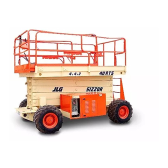
Model
25RTS
33RTS
40RTS
3120826
March 12, 2004
EUROPEAN OFFICE
JLG INDUSTRIES (EUROPE)
Kilmartin Place,
Tannochside Park
Uddingston, Scotland, G71 5PH
Telephone: 01698 811005
Main Fax: 01698 811055
Parts Fax: 01698 811455
CORPORATE OFFICE
JLG INDUSTRIES, INC.
1 JLG Drive
McConnellsburg, PA.
17233-9533
USA
Telephone: (717) 485-5161
Fax: (717) 485-6417
Advertisement
Table of Contents

Related Manuals for JLG 25RTS


Summary of Contents for JLG 25RTS
- Page 1 Model 25RTS 33RTS 40RTS 3120826 March 12, 2004 AUSTRALIAN OFFICE EUROPEAN OFFICE CORPORATE OFFICE JLG INDUSTRIES, INC. JLG INDUSTRIES (EUROPE) JLG INDUSTRIES, INC. P.O. Box 5119 Kilmartin Place, 1 JLG Drive 11 Bolwarra Road Tannochside Park McConnellsburg, PA. Port Macquarie, Australia...
-
Page 3: Hydraulic System Safety
• USE ONLY APPROVED, NONFLAMMABLE CLEANING ous pressures. Every effort should be made to SOLVENTS. relieve any system pressure prior to disconnecting or removing any portion of the system. 3120826 – JLG Sizzor –... - Page 4 Revised - September 30, 1999 Revised - February 29, 2000 Revised - March 14, 2001 Revised - September 18, 2001 Revised - April 15, 2002 Revised - September 25, 2002 Revised - March 12, 2004 – JLG Sizzor – 3120826...
-
Page 5: Table Of Contents
Hydraulic Circuit Checks ............3-1 3120826 – JLG Sizzor –... - Page 6 Electrical Schematic (Deutz) - Sheet 2 of 2 ......... .3-17 – JLG Sizzor –...
- Page 7 Electrical System Troubleshooting..........3-9 3120826 – JLG Sizzor –...
- Page 8 TABLE OF CONTENTS This page intentionally left blank. – JLG Sizzor – 3120826...
-
Page 9: Section 1. Specifications
NOTE: All wheel lugs must be torqued at 90 ft lbs. every 50 Battery - 85 Amphour, 550 Cold Cranking Amps hours. Fuel Consumption Low RPM - 6.7 lph (1.8 gph) High RPM - 11.4 lph (3.0 gph) Horsepower - 40 @ 3000 RPM 3120826 – JLG Sizzor –... -
Page 10: Performance Data
Extension with Deck Extended NOTE: Hydraulic oils must have anti-wear qualities at least to API Service Classification GL-3, and sufficient 25RTS - Main Deck - 570 kg (1,250 lb) chemical stability for mobile hydraulic system ser- Extension -230 kg (500 lb) vice. - Page 11 SECTION 1 - SPECIFICATIONS 3120826 – JLG Sizzor –...
- Page 12 SECTION 1 - SPECIFICATIONS – JLG Sizzor – 3120826...
- Page 13 Texaco Code 1912 grease MAINTENANCE REQUIRING PLATFORM TO BE ELEVATED. prior to assembly. NOTE: When temperatures remain consistently below -7° C ( 20° F ), JLG Industries recommends the use of Mobil DTE11. 3120826 – JLG Sizzor –...
-
Page 14: Pressure Settings
SECTION 1 - SPECIFICATIONS NOTE: Aside from JLG recommendations, it is not advisable 1.5 PRESSURE SETTINGS to mix oils of different brands or types, as they may not contain the same required additives or be of 2-W/S comparable viscosities. If use of hydraulic oil other... -
Page 15: Serial Number Locations
3° with the platform raised. If the machine is oper- Cylinder (5.1) (35.6) (3.2) ated on a 3° slope with the platform completely lowered, only the warning light is illuminated. Steer Cylinder 1.25 (6.4) (18.1) (3.2) 3120826 – JLG Sizzor –... -
Page 16: Major Component Weights
Arm Assembly- 33 RTS (Includes 3130 1418 Tires (Balasted Only) Lift Cylinder) Engine (Ford) Arm Assembly- 40 RTS (Includes 3860 1750 Lift Cylinder) Engine (Deutz) Chassis with Pneumatic Tires 3398 1541 Chassis with Foam Filled Tires 4102 1860 – JLG Sizzor – 3120826... -
Page 17: Section 2. Procedures
2. Discard bearings if the races and balls (or rollers) are pitted, scored, or burned. 3120826 – JLG Sizzor –... -
Page 18: Lubrication Information
Good grade mineral oils, with viscosities suited to the ambient temperatures in which the machine is oper- ating, are recommended for use. – JLG Sizzor – 3120826... -
Page 19: Cylinders - Theory Of Operation
Refer to Section 1 for an explanation of the lubricant ranges. key designations appearing in the Lubrication Chart. 2. JLG recommends Mobilfluid 424 oil, which has an SAE viscosity of 10W-30 and a viscosity index of 152. 2.4 CYLINDERS - THEORY OF OPERATION Cylinders are of the double acting type. -
Page 20: Component Functional Description
1. Using all applicable safety precautions, activate allows the platform to be lowered in the event hydraulic hydraulic system and fully extend cylinder to be power is lost. checked. Shut down hydraulic system. – JLG Sizzor – 3120826... -
Page 21: Cylinder Removal And Installation
If leakage continues at a rate of 6-8 drops per minute or more, cylinder repairs must be made. If the retract port is leaking, the piston seals are defective and must be replaced. If the extend 3120826 – JLG Sizzor –... -
Page 22: Cylinder Repair
3. Operate the hydraulic power source and extend the cylinder. Shut down and disconnect the power source. Adequately support the cylinder rod, if appli- cable. CYLINDERS WITH DOUBLE HOLDING VALVES. BEFORE REMOV- ING HOLDING VALVES CRACK BLEEDER TO RELEASE PRES- SURE. – JLG Sizzor – 3120826... - Page 23 SECTION 2 - PROCEDURES Figure 2-5. Arms and Platform Positioning and Support, Cylinder Repair 3120826 – JLG Sizzor –...
- Page 24 13. Remove piston spacer, and head, from the rod. Dis- card the o-rings, back-up rings, rod seals, and wiper seals. 14. Remove the cylinder head gland. Remove the rod from the holding fixture. – JLG Sizzor – 3120826...
- Page 25 CYLINDER LEAKAGE AND IMPROPER CYLINDER OPERATION. 16. Inspect the oil ports for blockage or the presence of dirt or other foreign material. Repair as necessary. 17. If applicable, inspect piston rings for cracks or other damage. Replace as necessary. 3120826 – JLG Sizzor –...
- Page 26 NOTE: The Steer Cylinder uses snap rings to secure piston. 10. Prior to setscrew installation spot drill rod before installing the setscrew(s) which secure the piston attaching nut to the diameter groove. Figure 2-13. Piston O-Ring Installation 2-10 – JLG Sizzor – 3120826...
- Page 27 Refer to Table 2-2, Holding Valve Torque barrel cylinder. Ensure that the piston loading o-ring Specifications. and seal ring are not damaged or dislodged. 3120826 – JLG Sizzor – 2-11...
-
Page 28: Tilt Alarm Switch
4. Adjust leveling nuts to obtain the highest possible voltage reading. 5. Check voltage at trip point in all four directions. If voltage reading is not symmetrical, repeat step (4) above. Figure 2-15. Tilt Alarm Switch - Manual Adjustment 2-12 – JLG Sizzor – 3120826... -
Page 29: Limit Switch Adjustment Procedure
Fill reservoir with recommended hydraulic fluid, which should be passed through a 10 micron (nominal, no bypass) filter prior to entering the reservoir. The use of contaminated fluid will cause damage to components, which may result in unexpected machine movement. 3120826 – JLG Sizzor – 2-13... -
Page 30: Throttle Checks And Adjustments - Ford
- 240 psi) minimum during forward or reverse opera- tion. Continue to cycle slowly between forward and reverse for at least five minutes. Shut down prime mover, remove gauges, and plug ports. Check reservoir level and add fluid if necessary. 2-14 – JLG Sizzor – 3120826... - Page 31 SECTION 2 - PROCEDURES Figure 2-18. Throttle Checks and Adjustments - Ford E-301 SPEED GAIN (LOW ENGINE) SPEED (HI ENGINE) Figure 2-19. Precision Governor Adjustments (1600269 Controller) 3120826 – JLG Sizzor – 2-15...
- Page 32 SECTION 2 - PROCEDURES E - 401H Figure 2-20. Precision Governor Adjustments (1600325 Controller) 2-16 – JLG Sizzor – 3120826...
-
Page 33: Throttle Checks And Adjustments - Deutz
2. If the ambient temperature is not 21° C (70°F), an addtional adjustment is required. As follows: a. Loosen the three cover plate screws. b. Adjust the cover to open the choke plate.8 mm (1/32 in.).. 3120826 – JLG Sizzor – 2-17... -
Page 34: Hydraulic Component Start-Up Procedures And Recommendations
Start the engine and run at the lowest possi- ble RPM until charge pressure has been established. Excess air should be bled from the system lines as close to the motors as possible. 2-18 – JLG Sizzor – 3120826... -
Page 35: Pressure Setting Procedures - (2 W/S)
Pressure to: to run the engine at low idle and tighten the system 25RTS - 90 bar (1300 psi) lines as soon as oil is observed to leak from them. When oil is observed to "leak" at the motor the line is... - Page 36 SECTION 2 - PROCEDURES Figure 2-21. Pressure Adjustment Locations (2 W/S) 2-20 – JLG Sizzor – 3120826...
-
Page 37: Pressure Setting Procedures - (4 W/S)
(1500 psi). 8. Bottom out Lift Overload functions and adjust Lift Up Relief Pressure as follows: 25RTS - 90 bar (1300 psi) Figure 2-22. Oscillating Axle Cam Valve 33RTS - 106 bar (1550 psi) 1. Making sure that machine is on a level surface and 40RTS - 138 bar (2000 psi) rear wheels are blocked, disengage drive hubs. - Page 38 SECTION 2 - PROCEDURES Figure 2-24. Pressure Adjustment Locations (4 W/S) 2-22 – JLG Sizzor – 3120826...
-
Page 39: Lockout Cylinder Check
1. Place a 20 cm (8 in.) high block with ramp in front of left front wheel. 2. Activate machine hydraulic system from platform control station. 3120826 – JLG Sizzor – 2-23... - Page 40 Shoes should be snug fit to pis- ton. Face of shoes should be flat and free of scoring and flaking. Do not lap piston shoes. 3. Compress pin keeper and install in spline area of piston block. 2-24 – JLG Sizzor – 3120826...
- Page 41 10. Install new o-ring on back plate. 11. Install back plate on housing. 6. Install pivot, spider, and piston assemblies in piston block assembly. 12. Install six cap screws and torque to 20-24 Nm (15-18 ft lbs). 3120826 – JLG Sizzor – 2-25...
- Page 42 SECTION 2 - PROCEDURES Figure 2-26. Piston Drive Motor 2-26 – JLG Sizzor – 3120826...
-
Page 43: Drive Torque Hub - 2Wd/4Wd Rear
Remove o-ring from flange of cover cap. Discard 16. Remove thrust washer from around spindle. o-ring. g. Remove pipe plug from cover. 17. Lift internal gear out of hub. 3120826 – JLG Sizzor – 2-27... - Page 44 Some gear packages roll with more difficulty than others. Do not be concerned if gears seem to roll hard as long as they roll with consis- tency. 2-28 – JLG Sizzor – 3120826...
- Page 45 8. Press bearing cone onto spindle in hub. 5. Set hub onto its large end. Place bearing cone into bearing cup. 9. Place spacer onto spindle in hub. 3120826 – JLG Sizzor – 2-29...
- Page 46 NOTE: O-ring may be stretched or pinched together to make it fit counter bore exactly. 12. Oil all exposed surfaces inside hub. 13. Place internal gear into hub so that its internal splines mesh with external splines of spindle. Oil internal gear. 2-30 – JLG Sizzor – 3120826...
- Page 47 18. Using retaining ring pliers, insert retaining ring into groove on input shaft by compressing spring and spacers together. 22. Place thrust spacer on top of input gear. 19. With large, splined end down, place input shaft assembly into spindle. 3120826 – JLG Sizzor – 2-31...
- Page 48 5. Place one thrust washer onto the end of planet shaft inside carrier. Fit tang of thrust washer into the slot on the inside edge of the planet shaft hole. 2-32 – JLG Sizzor – 3120826...
- Page 49 “X”-marked shoul- der bolt in ring gear over one of the shoulder bolt holes in hub. Mark location of shoulder bolt holes on outside of ring gear and hub. 3120826 – JLG Sizzor – 2-33...
- Page 50 6. Torque both bolts to 4 - 5 Nm (36 - 49 in. lbs.). 7. With large end down, place disconnect cap onto cover cap, aligning pipe plug hole in disconnect cap over pipe plug hole in cover cap. 2-34 – JLG Sizzor – 3120826...
-
Page 51: Drive Torque Hub/Brake - 4Wd Front
17. Torque shoulder bolts to 25 - 34 Nm (18 - 25 ft. lbs.). if brake has reset itself. If brake has reset roll Torque bolts to 25 - 34 Nm (18 - 25 ft. lbs.). checker should not be able to turn. 3120826 – JLG Sizzor – 2-35... - Page 52 SECTION 2 - PROCEDURES Figure 2-27. Drive Torque Hub - 2WD/4WD Rear 2-36 – JLG Sizzor – 3120826...
- Page 53 31. Remove two magnetic pipe plugs from pipe plug d. Remove needle rollers and spacer from inside holes in flange of hub. cluster gear. e. Repeat steps (a) through (d) to remove two 32. Hammer out nine studs. remaining cluster gears. 3120826 – JLG Sizzor – 2-37...
- Page 54 7. Place thrust washer onto spindle/brake so it rests on ing cluster gears. bottom of internal gear. 8. Assemble input shaft as follows: a. Place one spacer, spring, and other spacer, IN THAT ORDER, onto smooth end of shaft. 2-38 – JLG Sizzor – 3120826...
- Page 55 With large end down, place disconnect cap onto cover. Align pipe plug hole in disconnect cap over pipe plug hole in cover cap. h. Place two remaining bolts into bolt holes in dis- connect cap and tighten. 3120826 – JLG Sizzor – 2-39...
- Page 56 SECTION 2 - PROCEDURES Figure 2-28. Drive Torque Hub/Brake - 4WD Front 2-40 – JLG Sizzor – 3120826...
-
Page 57: Drive Brake - 2Wd/2Ws Rear
4. Insert shaft assembly and retaining ring in housing. male end of shaft. 10. Remove retaining ring and bearing from shaft. 11. Press rotary oil seal from housing. 5. Insert dowel pins, spring retainer, and springs (5 & 6) in housing 3120826 – JLG Sizzor – 2-41... - Page 58 NOTE: Discs and friction discs should remain dry during installation. No oil residue should be allowed to con- taminate disc surfaces. 7. Place a new friction disc on shaft until it contacts return plate. 2-42 – JLG Sizzor – 3120826...
- Page 59 SECTION 2 - PROCEDURES Figure 2-29. Drive Brake - 2WD/2WS 3120826 – JLG Sizzor – 2-43...
-
Page 60: Spark Arrestor Muffler
WHEN REFUELING LPG POWERED SIZZOR LIFTS, ALWAYS FOL- LOW MANUFACTURERS SPECIFICATIONS AND/OR APPLICABLE REGULATIONS. 1. If machine is to be left overnight or longer, it must be parked outside or the LPG tank removed and stored outside. 2-44 – JLG Sizzor – 3120826... -
Page 61: Freewheeling Feature
To Engage Torque Hubs OUS INJURY OR DEATH. Engage (reverse) disconnect cap on both drive torque hubs by removing two attaching cap screws, turning cap around, then reinstalling and tightening cap screws. Figure 2-31. Drive Hub Engaged 3120826 – JLG Sizzor – 2-45... -
Page 62: Preventive Maintenance And Inspection Schedule
NOTE: This machine requires periodic safety and mainte- and the “INTERVAL” at which the inspection is to take nance inspections by a JLG Dealer. A decal located on the frame affords a place to record (stamp) place. Under the “AREA” portion of the table, the various inspection dates. - Page 63 23. Wheel Bearings (2 Wheel Drive) 24. Sizzor Arms 25. Safety Props 26. Sliding Wear Pads 27. Pivot Pins/Bolts 28. Switches, Ground Control 1,11 29. Control Tags *Inspection and Maintenance Code 10 to be performed annually 3120826 – JLG Sizzor – 2-47...
- Page 64 SECTION 2 - PROCEDURES This page left blank intentionally. 2-48 – JLG Sizzor – 3120826...
-
Page 65: Section 3. Troubleshooting
Illustrated Parts Manual for hydraulic diagram of the It should be noted that there is no substitute for a thor- various circuits. ough knowledge of the equipment and related systems. 3120826 – JLG Sizzor –... - Page 66 No electrical signal being sent to lift down control Refer to electrical troubleshooting table valve cartridge Lift down control valve cartridge not functioning Repair or replace lift down control valve cartridge properly Lift cylinder not functioning properly Repair or replace lift cylinder – JLG Sizzor – 3120826...
- Page 67 Damaged wiring on limit switch Repair or replace wiring Damage limit switch Replace limit switch Flow control valve not functioning properly Repair or replace flow control valve Flow control valve not properly set Reset flow control valve 3120826 – JLG Sizzor –...
- Page 68 Loose or damaged wire in control box wire har- Ensure proper connection of wire at the control ness switch. Using suitable test meter, perform continu- ity test on wire. repair or replace harness as neces- sary. – JLG Sizzor – 3120826...
- Page 69 Repair or replace valve Controller not functioning properly Replace controller Relief valve improperly set or not functioning prop- Reset, repair or replace valves as required erly Steer cylinder not functioning properly Repair or replace steer cylinder 3120826 – JLG Sizzor –...
- Page 70 Lockout valve defective Repair or replace valve Axle will not lock Air in lockout system Bleed lockout system Defective lockout valve Repair or replace valve Defective pressure reducing valve feeding lockout Repair or replace valve system – JLG Sizzor – 3120826...
- Page 71 Defective Adeco throttle actuator (Deutz) Repair or replace actuator Governor not functioning properly Repair or replace governor Defective electronic governor Replace governor Engine will not decelerate below high speed See engine will not accelerate above low speed 3120826 – JLG Sizzor –...
- Page 72 Sticking or binding valve spools, piston rod, etc Clean, repair or replace components as required Hydraulic oil not a t optimum operating tempera- Allow oil sufficient time to warm up ture Pump drive slipping Repair or replace drive – JLG Sizzor – 3120826...
- Page 73 Unplug ground control box harness from platform switch receptacle. check wire from applicable pin in plug to control box power switch for proper connection. Using suitable test meter, perform continuity test on wire. Repair or replace harness as necessary 3120826 – JLG Sizzor –...
- Page 74 Repair or replace alternator Travel warning horn inoperative Circuit breaker open Determine and correct cause Damaged wiring in horn circuit Replace horn Hourmeter inoperative Damaged wiring in hourmeter circuit Repair or replace wiring Inoperative hourmeter Replace hourmeter 3-10 – JLG Sizzor – 3120826...
- Page 75 SECTION 3 - TROUBLESHOOTING 2792368 A Figure 3-1. Hydraulic Schematic - Sheet 1 of 3 3120826 – JLG Sizzor – 3-11...
- Page 76 SECTION 3 - TROUBLESHOOTING 2792368 A Figure 3-2. Hydraulic Schematic - Sheet 2 of 3 3-12 – JLG Sizzor – 3120826...
- Page 77 SECTION 3 - TROUBLESHOOTING 2792368 A Figure 3-3. Hydraulic Schematic - Sheet 3 of 3 3120826 – JLG Sizzor – 3-13...
- Page 78 SECTION 3 - TROUBLESHOOTING Figure 3-4. Electrical Schematic (Ford) - Sheet 1 of 2 3-14 – JLG Sizzor – 3120826...
- Page 79 SECTION 3 - TROUBLESHOOTING Figure 3-5. Electrical Schematic (Ford) - Sheet 2 of 2 3120826 – JLG Sizzor – 3-15...
- Page 80 SECTION 3 - TROUBLESHOOTING Figure 3-6. Electrical Schematic (Deutz) - Sheet 1 of 2 3-16 – JLG Sizzor – 3120826...
- Page 81 SECTION 3 - TROUBLESHOOTING Figure 3-7. Electrical Schematic (Deutz) - Sheet 2 of 2 3120826 – JLG Sizzor – 3-17...
- Page 82 SECTION 3 - TROUBLESHOOTING This page intentionally left blank. 3-18 – JLG Sizzor – 3120826...
- Page 84 England Fax: (49) 421 693 5035 Fax: (61) 2 65 810122 Phone: (44) 870 200 7700 Fax: (44) 870 200 7711 JLG Latino Americana Ltda. JLG Europe B.V. JLG Industries (Norge AS) JLG Polska Rua Eng. Carlos Stevenson, Jupiterstraat 234 Sofeimyrveien 12 UI.
Need help?
Do you have a question about the 25RTS and is the answer not in the manual?
Questions and answers